Paul McClay
-
XY table wroks!
08/19/2020 at 09:55 • 0 commentsalready teased proto axes operating under load.
After those validated the basic idea cadded & cut parts for an XY table. Went together well and felt good in hand.
Today clamped the XY to a Dremel tool stand to run X&Y under fixed tool. Just faced 3x4mm because have that file because that's CDCNC work area. Also CDCNC run of that file highlighted cross coupling between - mainly - Y&Z with face areas in different planes depending on direction of cutter travel.
Worked great. Not detected anything out of plane. Faster feed than i think CDCNC ever went. Then tried deep cut (relatively) initially at low feed. Smelled bad, not surprisingly. Tried increasing feed. But before got out of too slow got to first corner and noted missed a few steps on the way. So abort. Tried to get close to mm/2 depth of cut. Measured 1/64 in.

Tried a deep (relatively) cut Expecting Z will need a counter weight. Even if can lift tool, still wouldn't be thrilled about wear on m3 screws.
Unexpected problem: the XY axes don't handle a descending load well but chatter. Tried some nut ideas. So can't swap XY into horizontal CDCNC layout. So thinking of vertical with counterweight/spring(near constant force)
CADed some of that layout. Could be ~5x5x10in with a little complexity. Else not quite so small.
To do:Al?
-
Metal!
08/20/2020 at 11:20 • 0 commentsDidn't hit any fundamental problem.
Lost a (haphazardly attached) anti-backlash nut on the first pocket.
Ran progressively deeper cuts in second pocket until hold-down clamps slipped. Vid shows penultimate pass. Hold-downs are limited because I don't have enough nuts to populate all the embedded nut positions under the spoil board.
Oh yeah, replaceable spoil board and integrated work holding.
![]()
-
Z
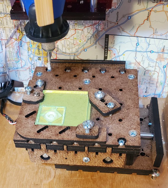
08/23/2020 at 03:06 • 0 commentsUsing one of the first lightly built test sliders and some close-enough wood scraps (no saw handy), cobbled a Z axis just to see if this has a chance of working. It does appear to have a chance.
Here exercising 5 cm travel in each axis:
With optimistic anticipatory debris screen because testing the XY table started to get a little messy.
My faux-Dremel weighed 510gf. A 500ml bottle of water weighed 510gf. Presumably 500ml beverage bottles are easy to find so makes sense to design for a user-provided counter weight.
Unloaded backlash/hysteresis is well under 50μm for all axis. The SM1545 motors have an axial spring to preload the bearings, and that compresses a bit when loaded in one direction. The laser cut parts have untested pilot holes for screws to limit the axial spring play.
-
First test drive
08/23/2020 at 04:18 • 0 commentsTo see what would happen, I ran some gcode from early #CDCNC testing. But faster. I think the CD mill did this at 350-400 mm/min iirc. For this first go with "1551" axis I set feed at 600 mm/min.
That was going pretty well until it died at 2.1 mm depth in the profile slot (of 2.3 mm to pocket bottom and 2.8 mm to complete the profile). No surprise. The slot profile was a mean test. #CDCNC never got anywhere near that far with the slot. For that project it wasn't long before I reCAMmed this job as 1) the pocket, then 2) another pocket surrounding the outside profile of the part, wider than a slot, with the outside face sloped so there was only one vertical wall to deal with. This just chewed thru 20 laps of the profile, with the spindle slowing down in the slot then regaining rpm when back in the pocket. I think that counts as success for the axes to feed hard enough to bog down the spindle motor.
This unfortunately highlighted a problem that I didn't have with the horizontal configuration of the CD mill: chips laying on top of the part and getting re-re-recut. I tried knocking them away with a toothbrush, but still ended up with acrylic froth crust on some surfaces. I figure that contributed to making the slot hard to cut. Not sure what to do about that. I was kinda liking the small footprint potential of the vertical configuration, and don't relish the idea of compressed air blowing chips around a tabletop.
![]()
Next up: is Z hysteresis small enough to run paths with varying Z vs a succession of descending waterline paths?
-
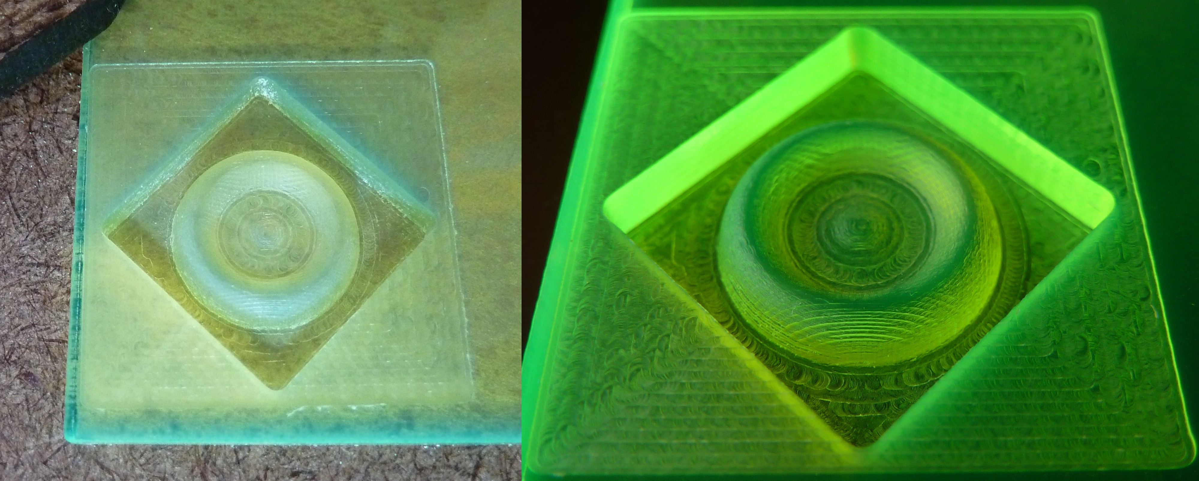
Rounder circles
08/23/2020 at 05:46 • 0 commentsConsidering the premise of using CD/DVD drive mechanics for milling, I thought #CDCNC did pretty well at making round circles. Especially compared with common results for glue-and-go CD/DVD-derived CNC projects.
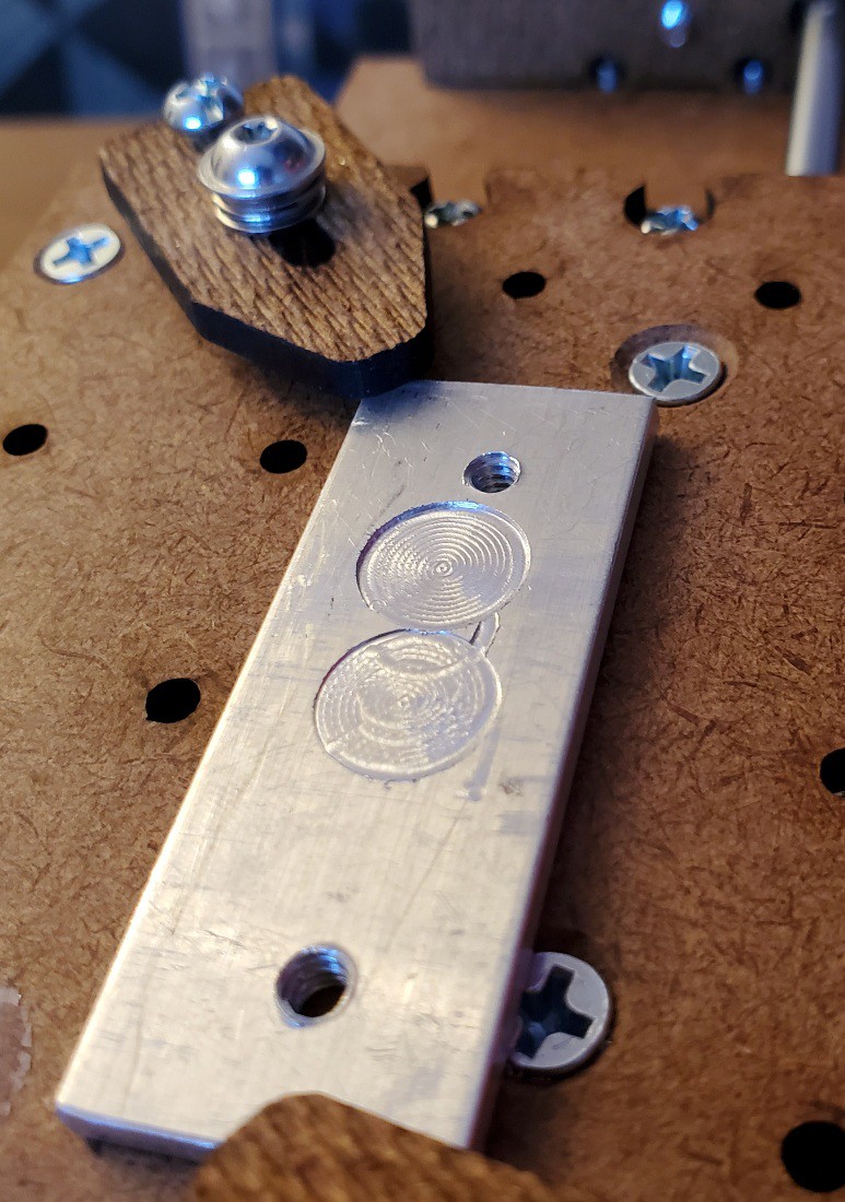
First try with this less constrained project, using a test part that I (mis)cut a lot of working on the prior project, yielded much rounder roundness:
![]()
The round part of each is ~11 mm diameter.
Note encrustation around inside of outer ring. Complained about that in prior log. I scrubbed more off with a wood toothpick.
(Apparently monochrome-on-black figures that are mostly edges compress very well. That 1900x1900 image compressed to 1 MB. I could resize it, but considering small data size, I'll post it big and tell myself that everyone's browsers will do something sensible with the large dimensional size. Lemme know if I should have told myself something different.)
-
Parallel Finishing
08/24/2020 at 18:11 • 0 commentsA couple logs back concluded with:
Next up: is Z hysteresis small enough to run paths with varying Z vs a succession of descending waterline paths?
(i.e. parallel finishing)
Yes.

sufficiently small Z backlash/hysteresis allows Z-varying tool paths The second pocket has other issues, but this isn't about that.
-
Backlash, chatter and fine parallel finishing
08/26/2020 at 02:35 • 0 commentsMy last session with this was mostly fiddling with the XY table without any clear victory.
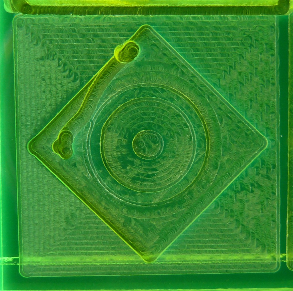
But first check out some curved surface finishing with fine step-over. 10% vs the 40% already shown in prior log:

10% step-over is less scallopy than 40%. No surprise. I just like the picture. Resetting the milling bit more carefully reduced runout which did clean up the pocket walls that I groused about last time, where the round thing closely approaches the middle of each side wall. In the photo above, the pocket wall to the upper right part of the left/latest pocket looks pretty flat and clean (wrt my expectations). The internal reflection of the slotted corner beyond it - the slot just visible in the crop above - shows clearly through the new pocket wall. More clearly so in person than the photo shows. I'll call that acceptable for this project. The wall opposite to that, which you can't see except for the top edge, looks pretty good too.
But the craggy wall in the upper left corner of the picture gives evidence of unsolved problems. Also the big square facing cut was less clean than the prior iteration, and both were less clean across the "top" (picture orientation) quadrant. This time I spotted that the X axis was chattering while moving one direction (as in the "top" quadrant) during the facing operation. Ok, so maybe I got greedy about squeezing out backlash. But both the craggy and clean visible pocket walls were cut with the X axis moving in that direction, so there is some cross-interaction too.
By the way, I thought some of the irregularity of prior tests might have been due to an axial pre-load spring in the motors yielding to force transients. So part of the last session was adding screws to pre-squeeze that preload, using pilot holes that I'd CADed into the laser cut parts but hadn't tried to use yet.
I did a lot of fiddling with trying to get that and the anti-backlash squeeze between the lead screw follower and the driven part of each axis tight but not binding.
The "chatter" problem appears to happen when an axis is yielding to force applied in the direction of motion. In other words, permitting the axis to move at a measured rate rather than pushing against resistance. This first turned up early on as the reason for arranging this machine vertically with a counter-weight instead of moving the heavy spindle horizontally like #CDCNC . When I first turned the XY table sideways, with Y vertical, it easily drove the Y axis up, against gravity, but chattered badly or stuck (lost sync with fast stepping) while bringing the axis down, with gravity. I tried a few things at that time including light oil and different nuts on the lead screw. Different combinations gave different results, varying in degrees of bad. So to keep moving I put the XY table horizontal and rigged the counterweight to offset the weight of the Dremel-clone spindle in vertical motion.
After reading a bit, last session started with trying PTFE dry lube to see if that would fix the chatter-on-descending and allow orienting Y vertically. Mainly since discovering appreciation for how the horizontal arrangement allows cut chips to fall off the workpiece. It did not.
At other points of adjusting the X & Y axes, one would move well against a small resistance but chatter and/or bind otherwise.
So at this point, it would be great if some better understanding of constrained-nut-on-spinning-screw dynamics happened to fall from the sky.
Some periodicity appears in the face cut (the left big square) shown above. Very clearly along the "bottom" (picture orientation) edge. Cutting that area seemed to go smoothly, so that's not the disruptive chatter problem. The period measures 1 mm. That's two turns of the lead screw. Unless nearness to 1 mm is simply an unlikely accident, I can't think of a source other than the lead screw. And I don't know how the lead screw would generate an effect every two revolutions. ??.
Bonus video for whoever reads (or skips) to the end. More useful for self-hypnosis by CNC rather than for new information. -
Homework
08/27/2020 at 01:55 • 1 commentIn the last episode, after some fruitless searching:
So at this point, it would be great if some better understanding of constrained-nut-on-spinning-screw dynamics happened to fall from the sky.
Today while following CNC on the Desktop Hack Chat and pondering what question I could ask that group, I found Orang Vahid Araghi's thesis from 2009: Friction-induced Vibration in Lead Screw Systems.
His introduction includes:
Disproportionate to the popularity of lead screws and their wide range of applications, very little attention has been paid to their dynamical behavior. Only a few works can be found in the literature that touch on the subject of lead screw dynamics and the instabilities caused by friction.
And regarding the first of two real-world examples discussed:
... an extra force applied ... in the direction of motion causes the system to generate audible noise, ...
This sounds like a) Orang couldn't find anything either, and b) he had to solve something like my problem.
His solution involves active motor controllers, which is probably out of scope for this project. But maybe there is enough clue in here to tell how to avoid triggering the "instability". At 277 pages, this may take some digging...
-
Thank you Orang
08/29/2020 at 04:44 • 0 commentsedit: more pix + result
tl;dr: while writing this it occurred to me that the simple answer may be conventional instead of climb milling.
Subject to further testing, it appears that Dr. Vahid has rescued me from not ever figuring this out on my own. His own thesis work is out of scope, but his literature review called out clues that I doubt I would have found apart from the context in which he framed them. Thanks, Orang.
About wicked chatter when force is applied in the direction of motion...
Yup, that can be a problem. Especially when the lead screw is/has:
- self-locking [M3x0.5: yup]
- low rotational inertia vs load inertia [wimpy screws/hefty XY table]
- low axial compliance [low=fit for purpose; high=unsuitable]
Well, that pretty much means "this project". And that
![]()
does not encourage.
About axial compliance:
- This chatter thing went from marginal to major after intentionally reducing axial compliance
- The CH-SM1545 motors (probably all these little can-stack stepper + lead screw assemblies) have asymmetric axial compliance because they have a spring on the motor end pushing the rotor/screw into a fixed bearing at the other end. Reviewing cases where similar motion in one direction or its opposite provoked more or less chatter: more chatter has correlated with loading against the unsprung end.
This wasn't a thing that I really wanted to corroborate. Springing the unsprung end so that the screw floats between two springs might quell chatter in both directions, but that won't help with accurate or repeatable positioning. Instead I tried to do the opposite.
About self-locking:
The screw self-locks due to its shallow pitch at (d/6)/rev. The fine pitch multiplies the force & precision possible from the tiny motor relative to what something like #CDCNC could get from a similar motor driving a steeper pitch screw as in a CD/DVD or similar scavengeable device. So that's a given for this project.
[Hey - anybody know what sort of scavengeable stuff uses finer pitch stepper+screw assemblies?]
So how about rotational inertia of the screw?
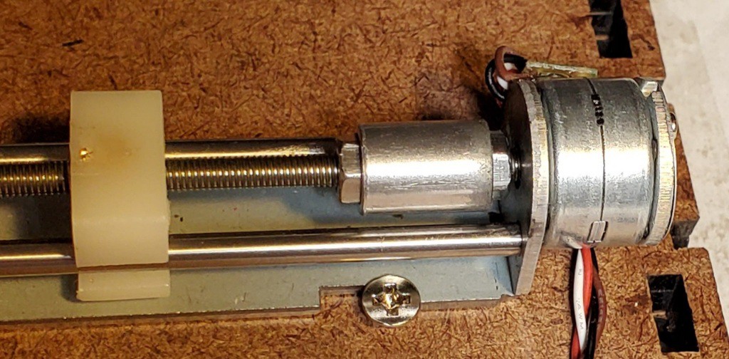
It would be nice if we could hang flywheel off an end of the screw, which is probably not often said around stepper motors, but both ends are captive. Instead I tried this:
![]()
"flywheel" -ish I really don't like how this eats up useful length of the screw.
Other side-effects that I really don't like include the screw jamming hard when it carries augmented rotational inertia to either end of travel. At least that gives evidence that it makes a difference. How much difference is necessary to shift the ratio of screw/load inertias from too small to safely less small? Dunno.
That randomly found piece is aluminum and smaller diameter than could potentially clear the ways. A couple of slightly larger diameter M3-threaded brass (or rhenium) disks jammed together would have the same or greater inertia in less length. But any metal part here adds to the BoM which I'd rather minimize. And I didn't find any really suitable standard part. Something like a pair of "DIN 467" nuts (that's a thing‽) but different. A best-fit part would be simple to turn on a lathe, but that departs further from the simple BoM intent.
But anyhow...
(edit: add pix + tweak text)
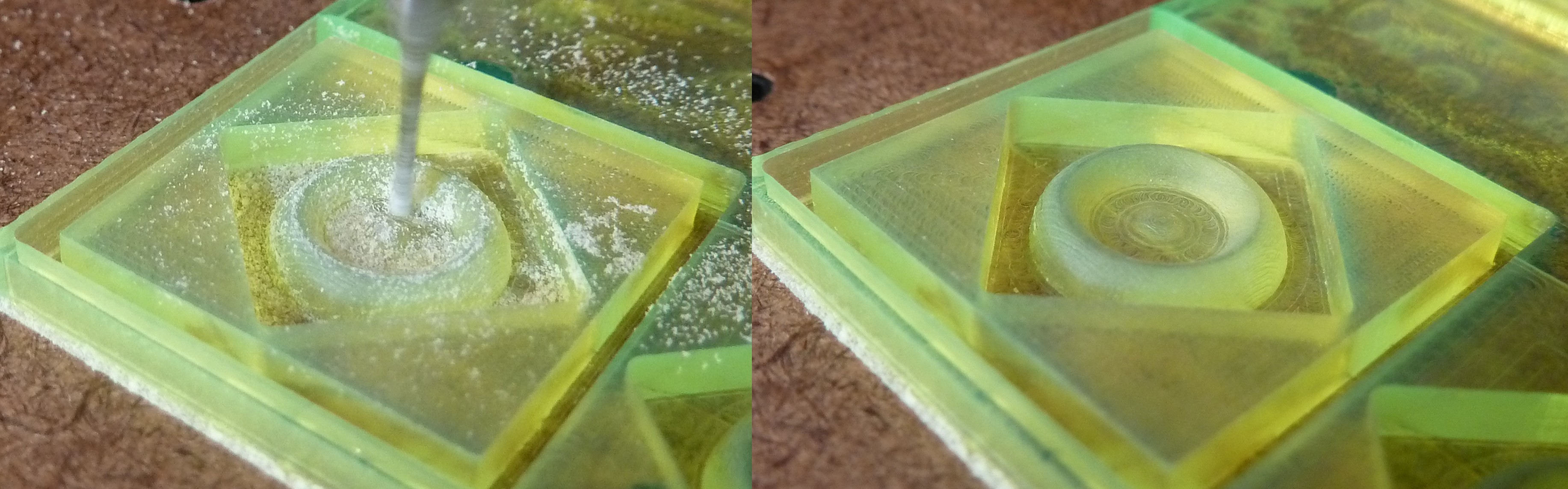
Adding "flywheels" to the X & Y screws seemed to work for calming the chatter out of, for one test case, the four quadrants of the initial facing cut around my test pattern and the beginning of the four walls of the pocket. That was somewhat encouraging but less than definitive because at the same time the Z axis was flaking out -- then flaked out.
![]()
(also shows runout and uneven cut depth of the two flutes) That test cut didn't get very far because the Z axis stopped lifting early in that job, so there isn't much to compare except the face cut and the first layers(?) of the square pocket. The sides of the pocket at least started straight. Some quadrants of the face cut had a slower/longer-period variation, but no chatter and no visible stutter to the X or Y motions.
On looking closer, that slower period variation was the Z axis floating up & down. Most dramatically on the right (decreasing Y). Apparently it's possible to balance that too well - or something. Unclear how that related to general failure of Z motion.
![]()
bouncing Z - views from above and oblique So maybe that added enough inertia to the screws, relative to inertia of the moving load, to escape from chatter prison. But coincident Z weirdness/failure leaves that a bit hazy.
The part I accepted without rethinking, until writing this log:
Tangential force in the direction of motion arises from "climb" milling - running a clockwise-turning cutter down the left edge of material standing to the right of the tool path - as opposed to "conventional" milling. The terms apparently have historical roots in manual machining before climb cutting became conventional for CNC machining.
Maybe the most direct way to avoid the problem is to avoid tangential force in the direction of motion by counter-conventionally running "conventional" tool paths.
If true, is that a known thing? Like, did everyone down at the CNC end of the bar already know to do climb cutting only on machines with backdrivable (or massive) lead screws?
(edit: add following)
And here's a test of "conventional" milling. After sorting Z axis.
![]()
click or see gallery for full resolution That does look better. Especially the four sides of the pocket.
The face cut looks quite regular in the horizontal/X-in-motion quadrants and a little less so in the vertical/Y-in-motion quadrants. I swapped the X & Y motor/screw units before cutting this pocket. I think I beat the crap out of the formerly-X unit while trying to sort this chatter thing. The X axis, which carries Y, has more inertia. Presumably that both aggravates the perilous ratio of screw/load inertias increasing likelihood of chatter, and increases the violence of each "chat". It was starting to sound rough even when running "smoothly". The lesser not-chatter roughness seems to have followed that unit from X to Y, suggesting that the unit has in fact suffered. I'm not sure how, but suspect the brass insert in the plastic slide may have made some wiggle room for itself.
The X & Y screws still have the "flywheels" -- and reduced range of motion. Removing those will test if conventional rather than climb milling suffices to avoid this sort of chatter.
I guess, in principle, I could have made it from "pulling = bad" via "climb = pull" to conventional milling without Dr. Vahid's lit review. But I maintain appreciation for that explanation of how applied force in the direction of motion really absolutely for sure can mess up a self-locking lead screw in some cases and thus the clearer focus on avoiding poisonous combinations or avoiding force in the direction of motion entirely. As opposed to thrashing variations to see if this or that might work without really understanding anything.
-
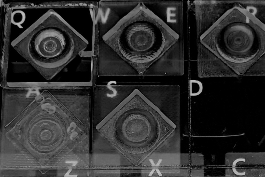
Made a thing
08/30/2020 at 03:33 • 0 commentsApart from an initial attempt and unsurprising failure to cut out the part at Q, I've just been trying to cut clean pockets without trying to cut out parts. The last log ended with the pocket at R which I'm willing to call "pretty good".
![]()
So it's time to try cutting a part!
It helps that exactly one month ago Stewart Allen checked in a "wide cutout" option for Kiri:Moto. That solves the cause of predictable failure at Q above (actually the failure is under W) without any other CAM gymnastics.
This time I double-stick taped the material in place. Kiri wanted to cut the part outline as part of the roughing operation before finishing the curvy bit. Kiri does support tabs, but I didn't want big tabs and didn't know how unbig the tabs could get without messing up the finishing operation. So, tape.
"Send File"...
![]()
click or see gallery for full resolution ...and this time it worked.
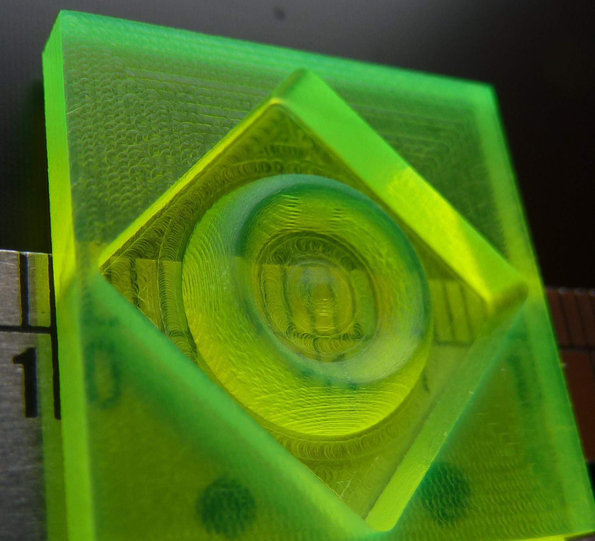
![]()
pocket has four beautiful straight flat smooth sides -- click or see gallery for full resolution ![]()
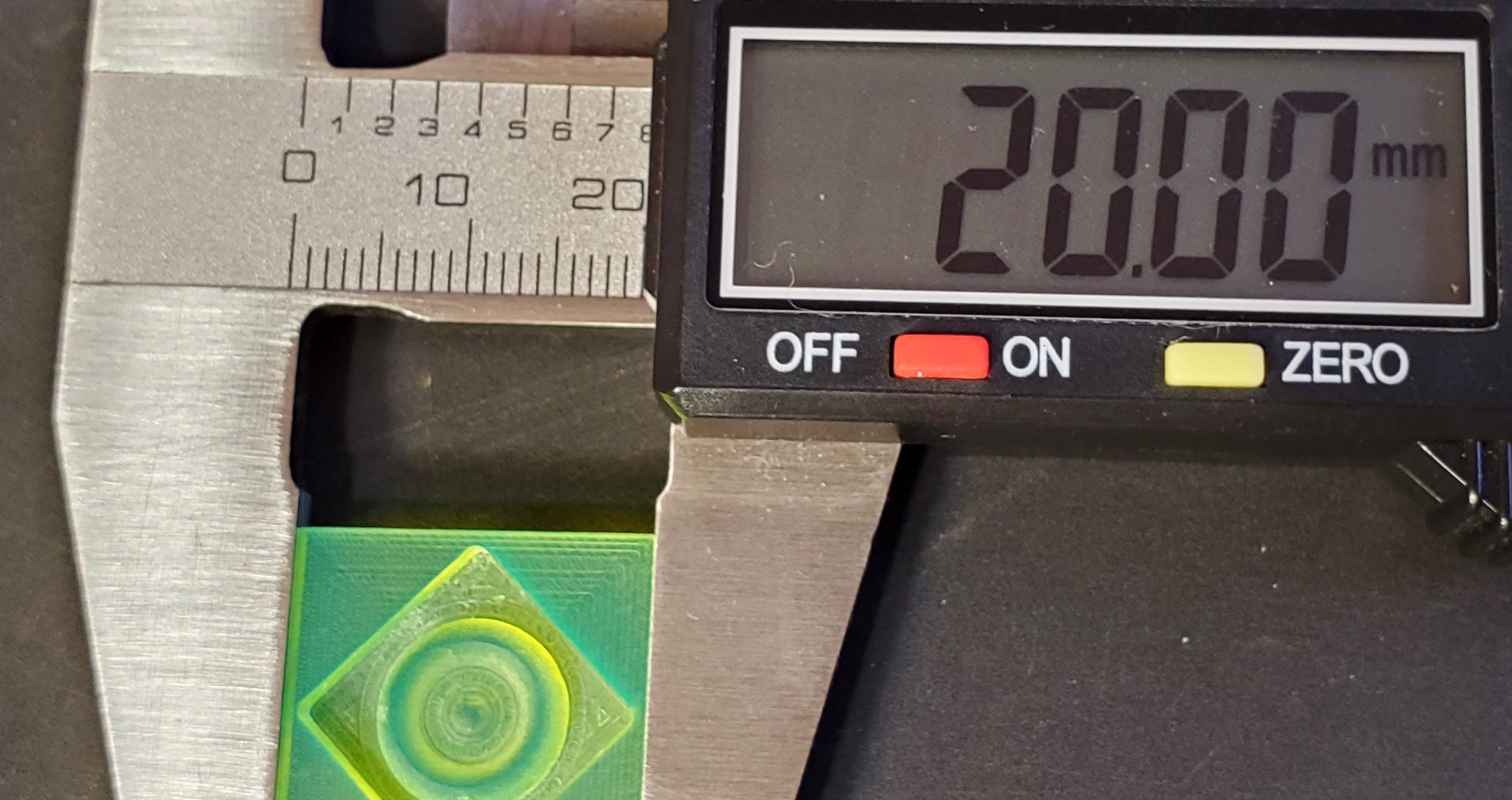
20 contours/mm - done that once prolly don't need to do it again ![]()
Ok, that's a cheat - I can squeeze the plastic more or less to dial-a-dimension Relative to my subjective hopes/expectations for this project, I'll say that turned out well.
Yay.
Next: try conventional milling without augmented lead screw inertia.
Minamil 2dc: a minimal CNC mill
Each axis: ̶$̶5̶ ̶$̶8̶ $10 motor+lead screw, 3x LM6UU, 3x 6mm x 100mm rod, 1/8in hardboard, PC case screws