• Capacitive Soil Moisture Sensor

    Tim09/14/2020 at 23:32 0 comments

    One curious type of sensor that can be realized with simple means is a soil moisture sensor to monitor wether plants need to be watered. A simple way of achieving this is to measure the soil resistivity with two electrodes. Unfortunately that is not very reliable due to corrosion of the electrodes.

    A much better approach is a capacitive sensor, for example as shown here. The sensing principle exploits the fact that water has a much higher (~80) relative dielectric constant than dry sol or air (~1). The sensing element consists of a planar capacitor that is directly inserted into the soil. This can be very easily realized by copper traces on a PCB that is insulated with solder resist. Coincidentally I found a sensing element that I designed years ago. The layout is shown here:

    Below you can see how it is inserted into a potted plant.

    https://cdn.hackaday.io/images/1108251600117492921.jpg

    Since this sensor is essentially a variable capacitor, it can be easily read out with the RFC peripheral. Since the capacitance of the sensor is relatively low, I chose a resistor of 47 kOhm to achieved a reasonably low frequency.

    Of course, the resistor does also directly influence current consumption of the oscillator, hence choosing a larger resistor is sensible.
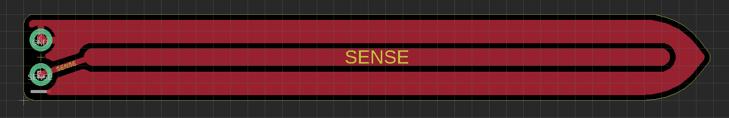
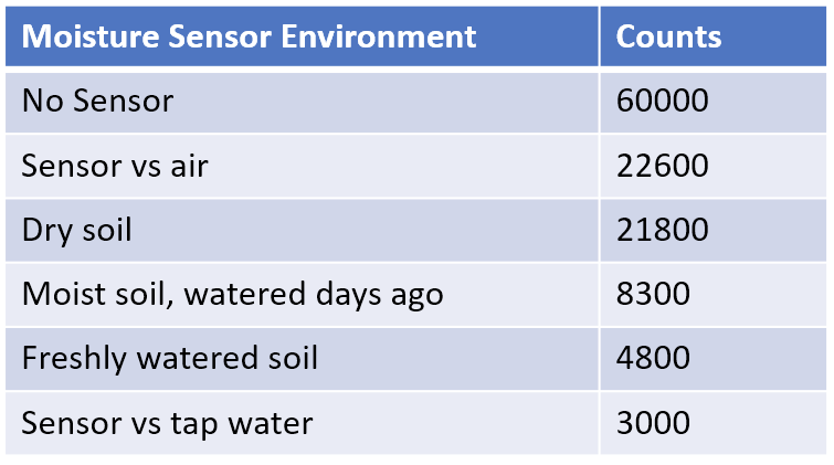
    The table above shows counts for a counting time of 40ms. The sensor capacitance vs. air is only about twice as high as the parasitic capacitance on the breadboard ("no sensor"). The counts strongly decrease in presence of water and its easy to distinguish a freshly watered plant from one that already dried up slightly.
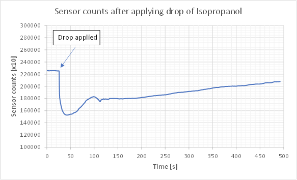
    One bonus experiment to verify that the sensing principle is indeed capacitive: I deposited a drop of isopropyl alcohol on the sensor and monitored counts over time as shown above. Isopropyl alcohol has a dielectric constant between that of air and water and is well isolating. Accordingly, the counts sharply drop after application of the drop due to an increase of sensor capacitance. The alcohol slowly evaporates which leads to a steady increase of counts over time proportional to the loss of volume.

    In summary, the RFC seems to be well suited for this application. Time for a design project?

  • Light Sensor based on an LED

    Tim09/14/2020 at 23:31 0 comments

    Using LEDs as light sensors is a hack tried by many. If operated under reverse bias conditions, LEDs act as photodiodes. Due to their small size, the generated photocurrent is extremely small, so some tricks have to be employed to measure it.
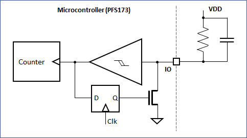
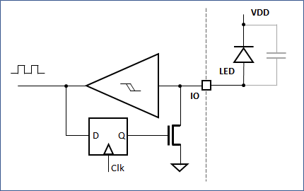
    The RFC allows for a very simple implementation. The circuit is shown above - the LED is connected with the anode to the RFC pin and the cathode to VDD. During the reset, the ground switch will charge the junction capacitance of the LED to 0.8xVDD negative bias. The photocurrent generated in the LED will slowly discarge this capacitance until the upper threshold is reached. The photocurrent is directly proportional to the number of counts within a certain time internal.


    I tested the concept with a red 5mm LED. Counting time was 500 ms. With these settings it was clearly possible to discern different light level from total darkness to direct bright light as shown in the table above.

    Since the GPIO can be reconfigured, it would be possible to use an LED in dual function as a light detector and indicator without having to add additional parts.

    A quick estimation how much current we are measuring:

    • Total charge in the charge LED is given by Q=C*V. Then we can calculate the Photocurrent by Iph=Q/tcnt, where tcnt = twindow/cnts, the time for a single count.
    • => Iph = cnts*C*V/twindow
    • The total discharge voltage is 5* (0.8-0.2) = 3V (Upper-lower trigger voltage)
    • Let's assume 50pF for the LED junction capacitance + parasitic capactiance of the breadboard.
    • Twindow= 500ms

    => Iph = cnts * 50pF*3V/500ms = cnts * 300 pA

    One count corresponds to only 300 pA of photocurrent!

    Of course, there are numerous imperfections in this set up, including leakage currents and nonlinear C(V) behavior, so we cannot expect a highly linear light sensor from this. But it should be sufficient if only a threshold needs to be detected.

  • Investigating the RFC

    Tim09/14/2020 at 23:22 0 comments

    The documentation found earlier by JS provides a basic functional explanation and has a list of registers, but is a bit light on details. Nothing that can't be investigated...

    The image above shows my interpretation of the "C-type" operation of the RFC. Basically it consists of a  schmitt trigger  and a ground switch. If an RC-couple (as shown) is connected between the IO-pin and the positive supply, the input voltage will slowly increase according to the RC time constant. If a certain trigger voltage is reached, the ground switch will short the input to ground until the lower trigger voltage is reached. Each time this happens, the counter increases by one. Effectively, this circuit forms a relaxation oscillator.

    By evaluating the number of counts during a fixed interval, it is possible to measure changes in the capacitance or resistance.

    The table above shows the register mapping. The control register allows selecting the specific pin. Bit 4 needs to be written to to start and stop the counter.

    __sfr __at(0x2d)          _rfcc;
    __sfr __at(0x2e)          _rfccrh;
    __sfr __at(0x2f)          _rfccrl;
    
    #define RFCC              _rfcc
    #define RFCCRH            _rfccrh
    #define RFCCRL            _rfccrl

     
    Register mapping is shown above.  Using the RFC is rather simple, as shown below:

    RFCC = 0xc0 | 0x08 | 0x02 ; // Select PB6, set to C-Mode, enable output
    
    uint16_t result;
    RFCC|= 1<<4; // start RFC
    _delay_ms(50);
    RFCC&=~(1<<4); // stop RFC
    result=(RFCCRH<<8)|RFCCRL;


    The scope picture shows the voltage on the RFC pin during operation. In this case a 100nF capacitor and 10 kOhm resistor were connected in parallel to VDD.

    It can be cleary seen that the charging of the RC element follows an exponential. The upper trigger voltage is 4V, the lower trigger voltage is ~700 mV. The origin of the ringing at the lower voltage is not clear to me, it seems to be an artifact of the RFC peripheral.

    The impedance of the ground switch seems to be relatively high. In this case, with the 100nF capacitor, it takes about 11 µs to discharge.

    When using a lower capacitor value, the counting frequency increases propertionally. The minimum discharge time seems to be 1 IHRC cycle (IHRC was 16 MHz in this device = 62.5 ns). In that case a voltage undershoot to 0V is observed. It is clear that operation of the RC oscillator will be instable when the reset voltage is not properly defined. It seems to be advised to adjust the capacitance value so that the reset time is either below one IHRC cycle (reset voltage will be 0V), or significantly above (reset voltage will be 700 mV).

    An additional parameter of interest would be how the oscillator frequency changes with supply voltage.

    I measured the frequency of an oscillator with R=10 kOhm and C=100nF for different values of VDD.

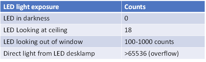
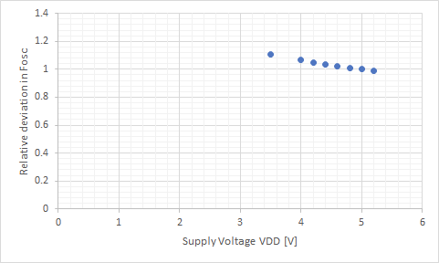
    It can be seen that there is a consistent variation of frequency. This is because the trigger voltages change according to the supply voltage. The lower trigger voltage seems to be defined by 0.2 * VDD, while the higher trigger voltage is defined at approximately 0.8 * VDD. The voltages are most likely directly derived from the supply with a resistive divider.

    A true symmetric relaxation oscillator would not show this voltage dependence, but since the discharge is defined by the ground switch, a dependence on switching voltages is introduced. A variation of ~10% accross a 1.5 V supply difference should be good enough for many applications, though.

    Great, looks like the RFC works exactly as (not) advertised. What can we use it for?

  • Identifying Undocumented I/O Registers

    Tim09/14/2020 at 22:38 0 comments

    Padauk is a Taiwanese supplier of ultra-low cost microcontrollers, notorious for the "3 cent MCU". The supplier itself only offers a closed tool chain with a proprietary C-style language. In the mean time, an open sourced and independently created tool-chain, partially based on reverse engineering, became available.

    There are still some areas that are not completely understood. One topic is the initial state of the I/O registers. The behavior of the real device is somewhat inconsistent to the datasheet, which may be due to an errata or due to different behavior of the proprietary and open toolchain.

    To investigate this behavior in detail on the Padauk PFS173-S16,  a small program was used to copy the entire I/O space to the RAM directly after startup. Since no indexed access of the I/O registers is possible, individual instructions had to be generated to copy each address.

    After proper initialization of the MCU peripherals, the I/O area back up is dumped via the serial port.

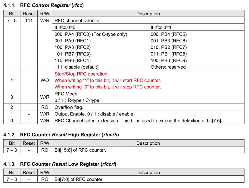
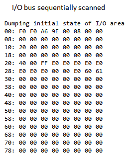
    The image above shows a dump of the entire I/O area directly after reset. There are 128 possible registers, but only some are used and documented - only few registers actually show a nonzero value.
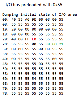
    One interesting aspect is that some values are repeated, like the 0xF0 in address 00 and  01. This is particularily striking since the registere at 0x01 is actually unused. Some more experimentation reveal that actually the content of the last access registers is repeated. The behavior looks very much like a floating internal bus - if the accessed register does not exist, no new information is written to the bus; the logic level from the last access is stored due to the parasitic capacitance. This would, of course, be a nice side channel if this were a security critical device. But we can still utilize this effect to identify which I/O addressed are actually utilized and which are not.

    To probe for unused registers, I simply wrote 0x55 to a known register directly before the I/O read. If the next read access was to an unused I/O location, it would read as 0x55 and could be easily identified. As you can see in the image above, many I/O addresses now read 0x55 and are therefore unused or write only. Most of the used registers could be easily crosschecked to the documentation.

    There are, however, a few registers that cannot be assigned. The first, marked in red, at 0x23 and a group, marked in green, at 0x2d,0x2e,02f. A bit further probing revelad that 0x2d is clearly a control register. Reset state is 0xE0. Bits 7-5,3,1,2 are R/W, Bits 4 and 2 RO or WO. 0x2e and 0x2f appeared to be read only.

    Some excellent sleuthing by JS in the EEVBlog-Forum revealed a very interesting explanation for the green registers: It seems that earlier padauk microcontrollers included a peripheral called the Resistance to Frequency Converter (RFC), which can still be found in an old datasheet version at a reseller. The bit configuration of these registers exactly follows the findings, so that there is a good chance for a match.

    It's not clear why this peripheral was left undocumented. It is still mentioned in the catalogue of Padauk, but not a single device with this feature set is listed.

    The purpose of the undocumented register 0x23 (red) could be easily identified: It actually contains additional LSBs of the ADC. It appears that Padauk has a standard IP block for a 11 bit ADC that was also used in the PFS173. For some reason it was declared as 8 bit ADC and the lower three bits were left undocuments. Possibly there is a noise issue?