 Bud Bennett
Lucy is my Border Collie & Schipperke mix dog. At nine years old, Lucy is blind now. She has Progressive Retinal Atrophy which has slowly taken her sight from her. But she still loves to chase after her stuffed toys or balls when they are tossed a few feet away. Unfortunately, she has trouble locating it if the toy takes an unexpected bounce. We purchased a chime ball to see if that would help. The ball must be switched on manually and emits a chiming sound every five seconds until it is switched off. Lucy can find the chime ball easily, but doesn't like it when the ball sounds off in her mouth.
I've designed a beeper to insert inside one of Lucy's stuffed toys. It will have a small LiPo battery for power. A LIS3DH accelerometer detects a free-fall condition when her toy is tossed into the air and begins emitting a tone to let her know where the toy is. After a few seconds the tone will stop until the toy is tossed again. At least that's the plan.
The LIS3DH accelerometer requires a microcontroller to program it, via a SPI interface after power is applied, otherwise it won't do anything. I chose a PIC16F18313 for the µC for the following reasons:
- Low power dissipation. Less than 0.1µA in sleep mode, and less than 30µA when running at 32kHz.
- Built-in SPI interface.
- 10-bit ADC to measure battery voltage.
- Wide power supply range - 2.3VDC to 5VDC
- SOIC8 package is pretty small.
After adding a MCP73832 battery charger and a few discrete components the circuit looks like this.:
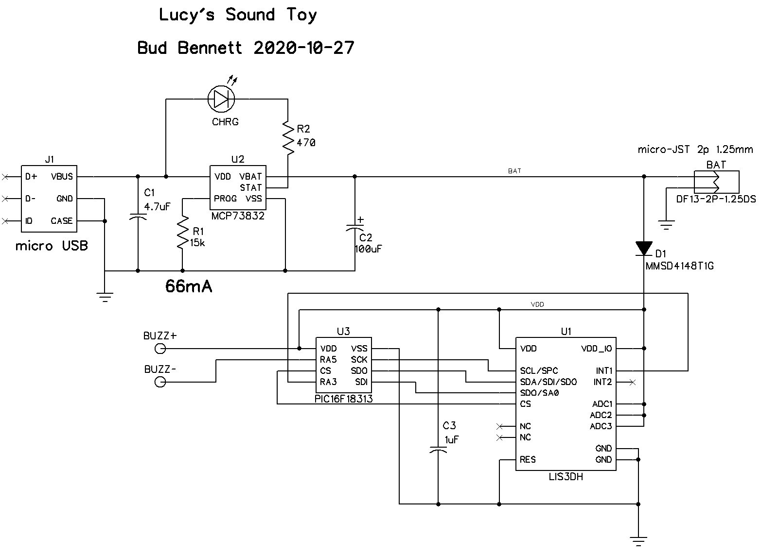
At the last minute I lost my nerve and added D1 to level shift the VDD voltage down to a max of around 3.6V. The LIS3DH has an absolute maximum VDD = 4.8V, but only specifies VDD=3.6V otherwise. If it can survive 4.2V, then D1 can be shorted out.
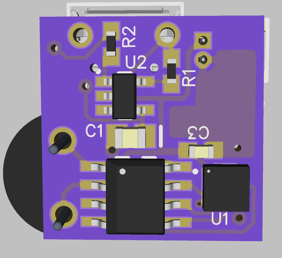
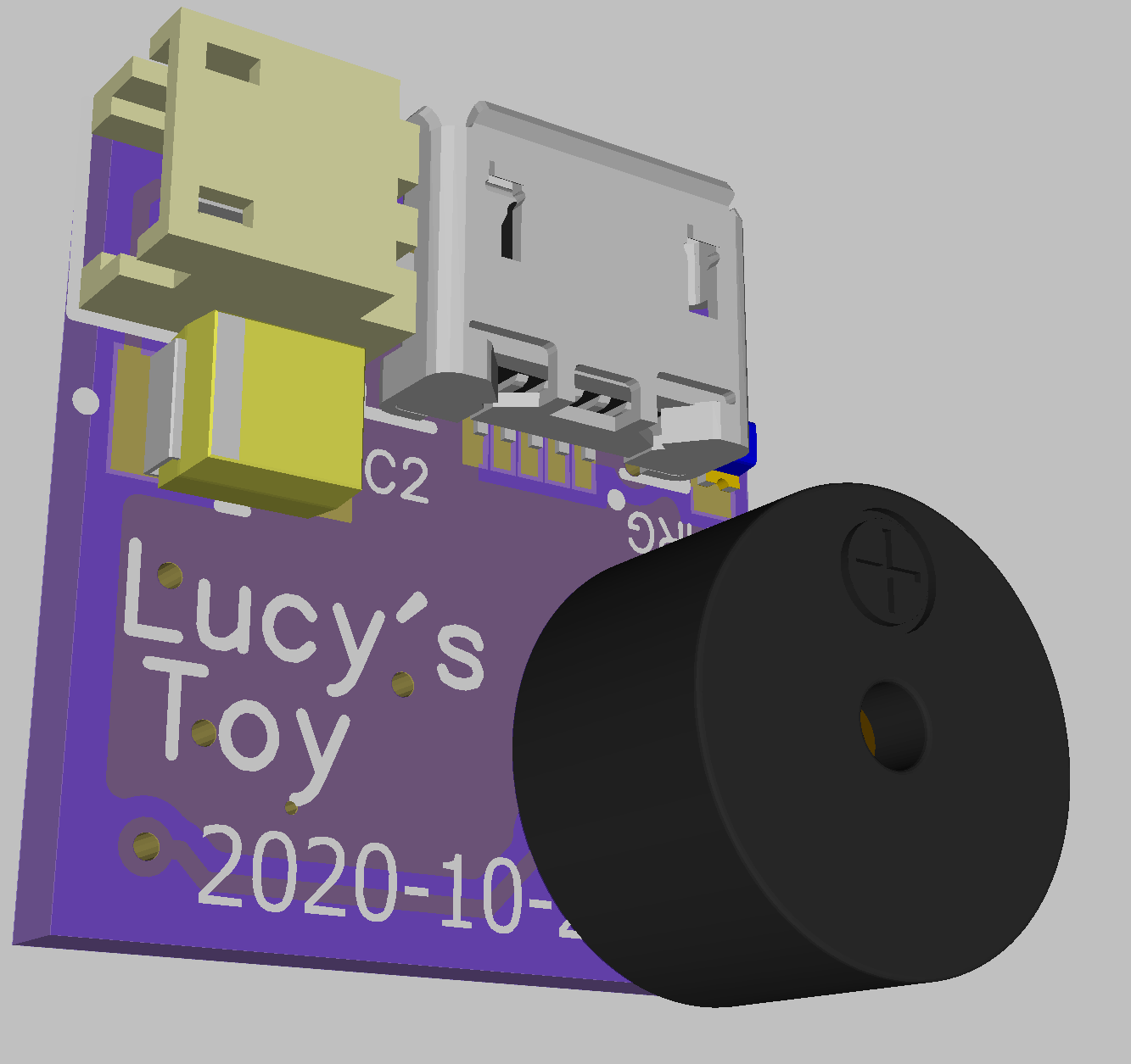
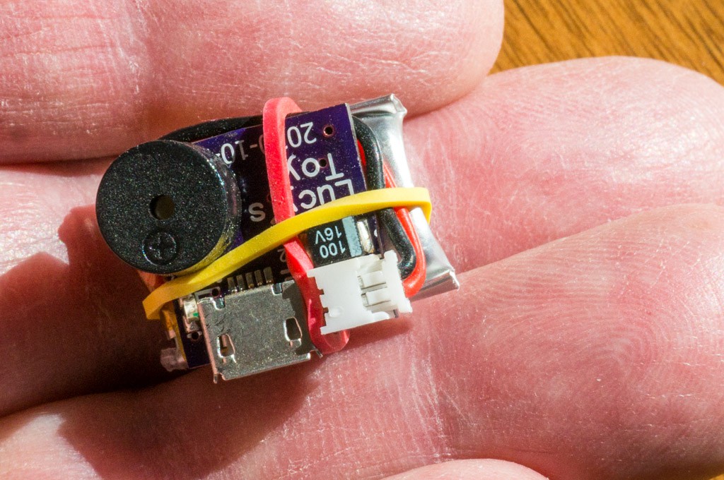
The PCB design is complete and measures 15mm x 15mm...the same dimensions as the 120mAh LiPo battery. I decided against using a lithium coin cell because I did not think that it could be attached well enough to survive the expected treatment. The LiPo will be attached with two small leads and a micro JST connector. It will probably be glued to the component side of the PCB. A micro USB jack, for charging, and a small buzzer completes the module.
Current Status:
At this point I have been able to program the PIC to configure the accelerometer to detect a free fall event, with appropriate delay, and trigger an interrupt input on the PIC. The PIC will then use the buzzer to emit a series of beeps for a couple of seconds and then a short 100ms beep every 2 seconds for 10 seconds. After that it goes to sleep and waits for another free fall event.
The PIC is using < 1µA during sleep mode. The LIS3DH is supposed to consume about 12µA when sampling at 25Hz. I figure that the 120mAh LiPo will need to be recharged about once per year.


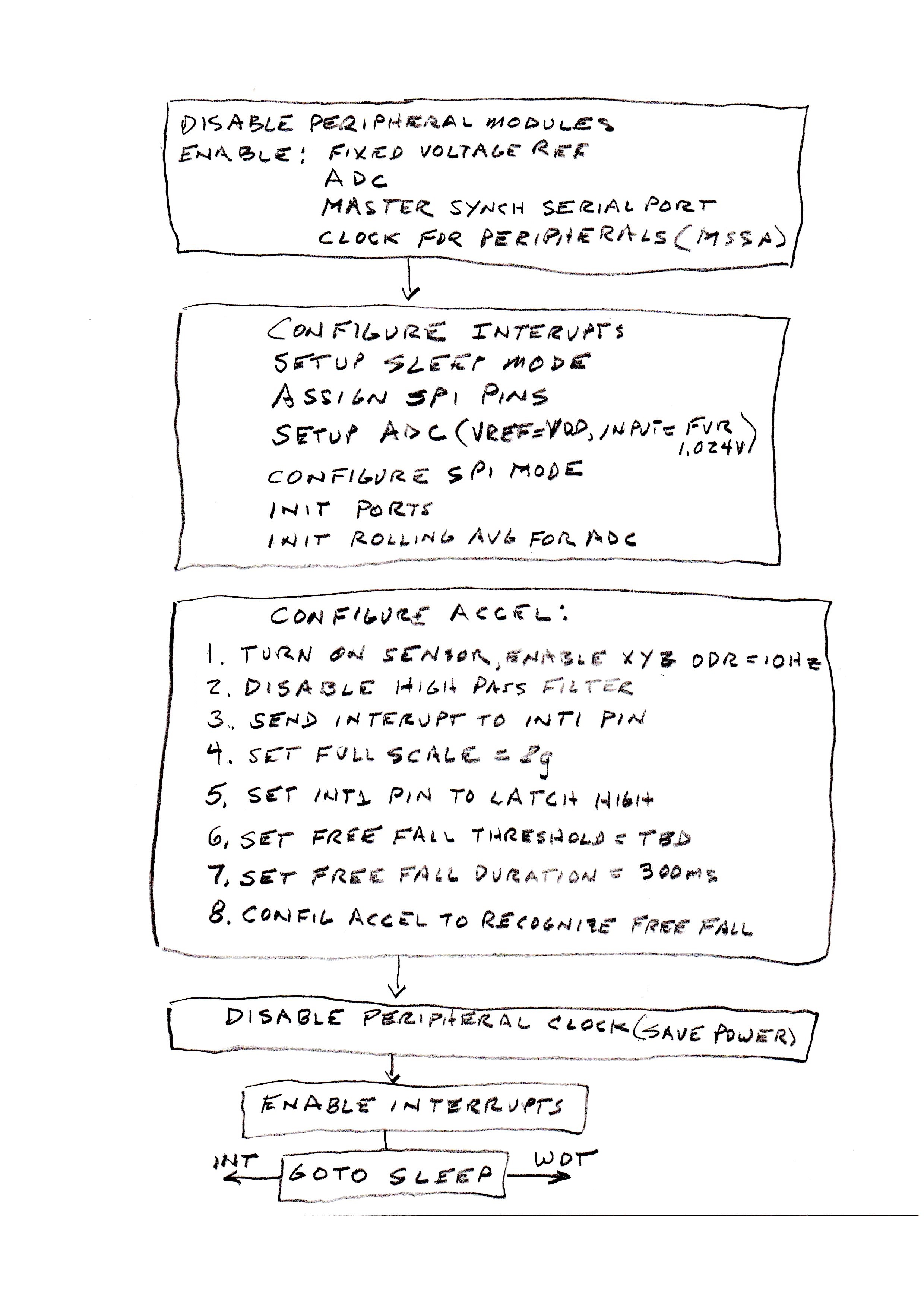 The chart above shows the steps necessary to configure the PIC and the accelerometer. Most of the peripheral modules are disabled. The only modules needed are the FVR, ADC, and MSSP (for the SPI interface). Then the modules are configured. The watchdog timer (WDT) is set to overflow after 264 seconds. The ADC is set to run on its own RC clock and place the 10-bit result so that the 8LSbs occupy the low byte of the two byte ADC result register. The SPI is set to match the protocol required by the accelerometer and is set to master mode since it controls the SPI clock (SCK). The I/O ports are set to digital with required input/output assignment. Lastly, the 8-byte ADC rolling average is zeroed out as a precaution.
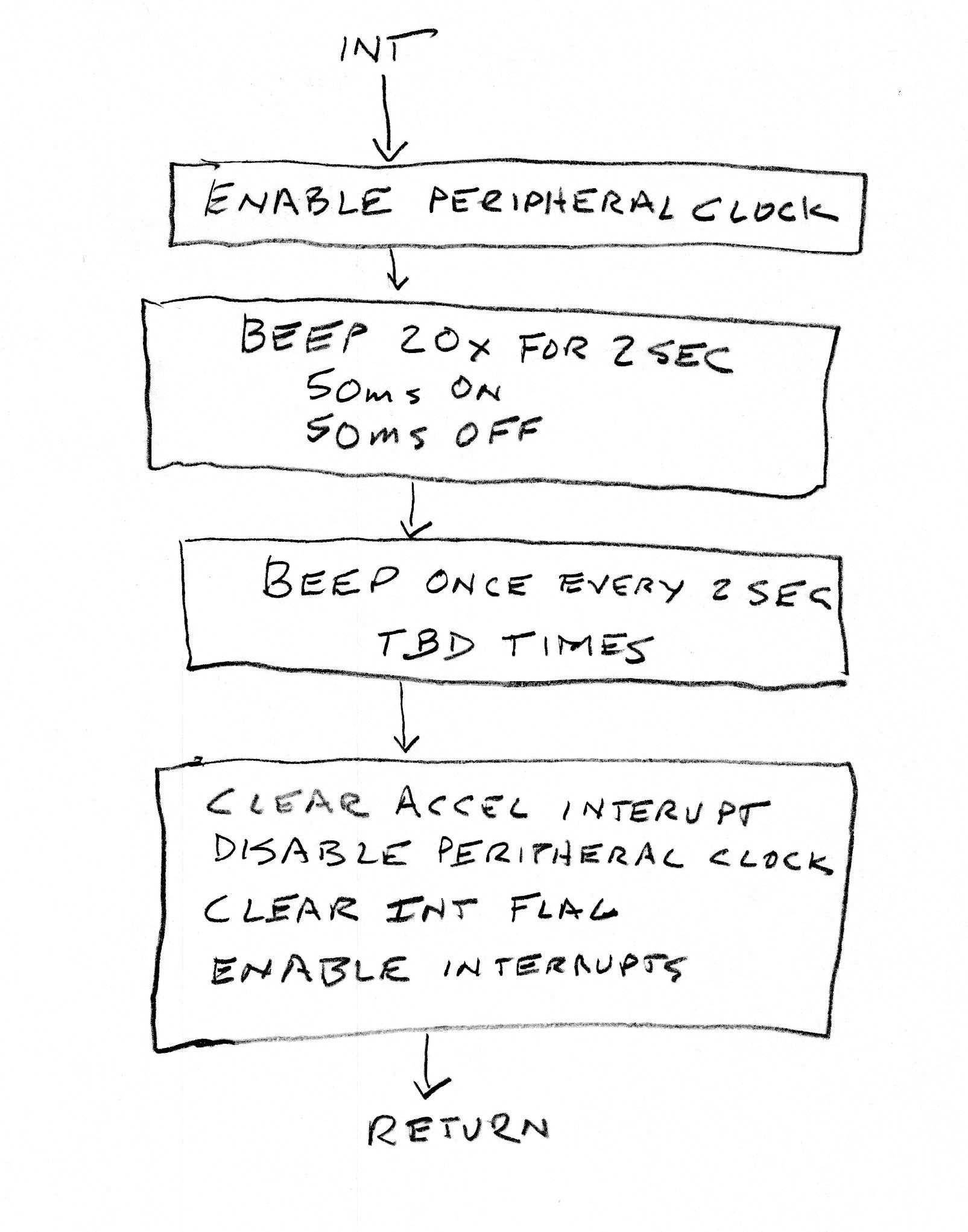 When the external INT pin is asserted the above routine wakes the PIC from sleep and executes. The beeper is exited in a series of 20 beeps (50ms on, 50ms off) for 2 seconds. Then there will be a 2 second pause and a 100ms beep, which repeats TBD times. After that the SPI is used to read data from the accelerometer to clear the interrupt event and unlatch the INT1 pin. PIC peripheral clocks are again disabled, the PIC interrupt flag is cleared and general interrupts are enabled. The routine returns to the running program -- most likely back to sleep.
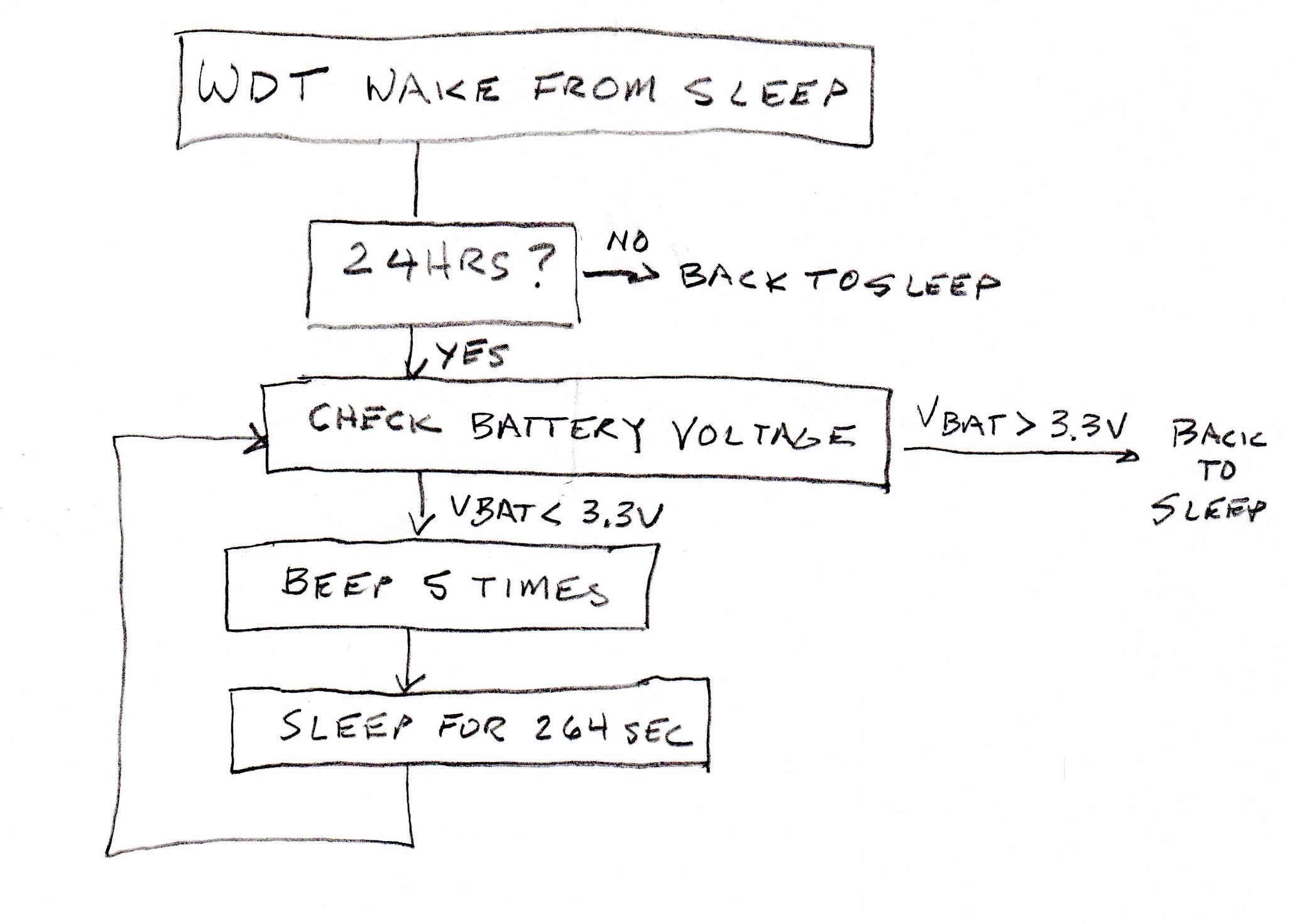 The WDT wakes up the PIC every 264 seconds. This routine counts out 24 hours before it checks the battery voltage. If the battery voltage is above 3.3V then the 24 hour timer is reset and the cycle begins again. If the battery voltage is below 3.3V then the PIC will beep 5 times (so as not to get it confused with a smoke detector) and go back to sleep until the WDT wakes it again to repeat the battery voltage check. I'm hoping that it won't do this at 2:00am.


 tyrigi
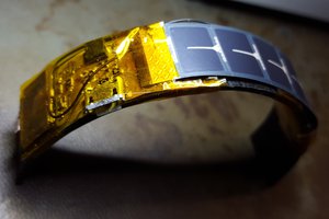
 DrYerzinia
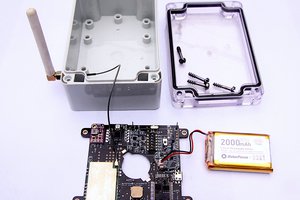
 Capt. Flatus O'Flaherty ☠
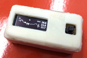
 Linus Dillon
Depending on the type of buzzer, some buzzer manufacturers recommend a free-wheeling diode connected to the buzzer pins.
Measuring the voltage on the buzzer pins while it is buzzing can give more insights.
https://www.murata.com/en-us/support/faqs/products/sound/sounder/char/sch0001