 Mario Gianota
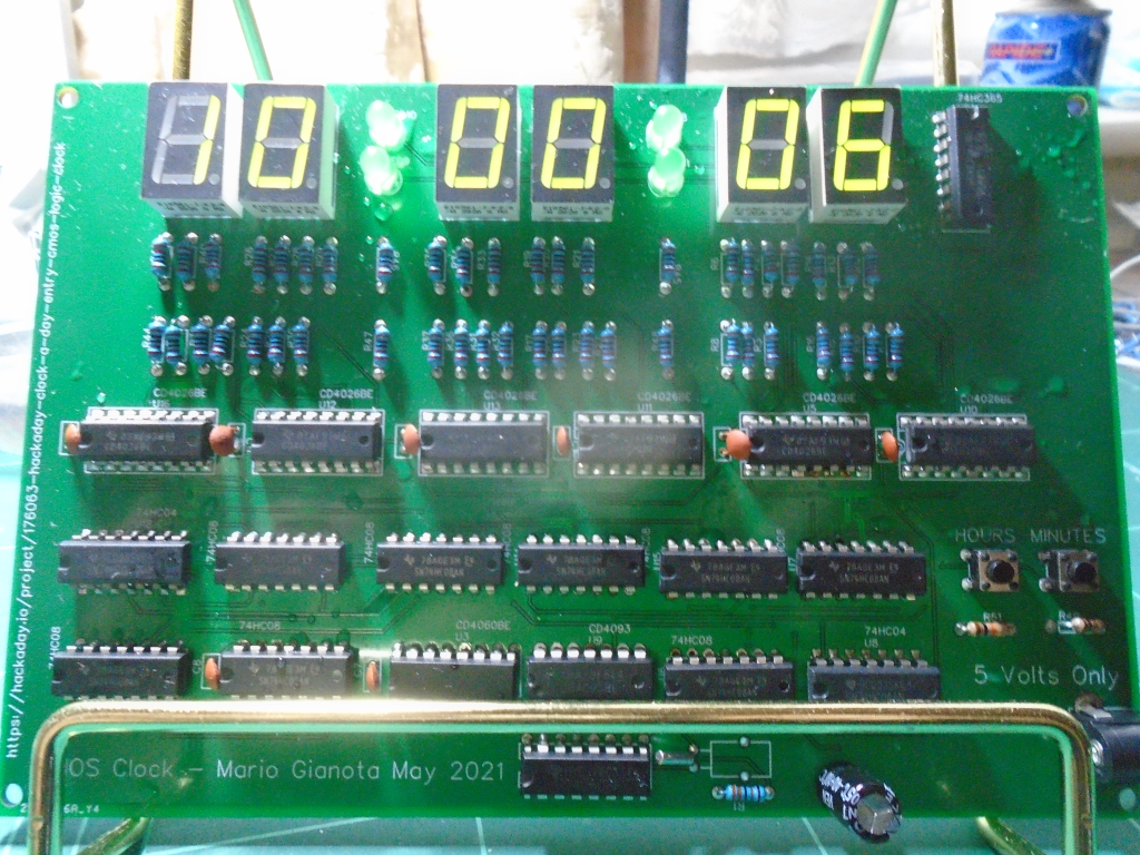
31
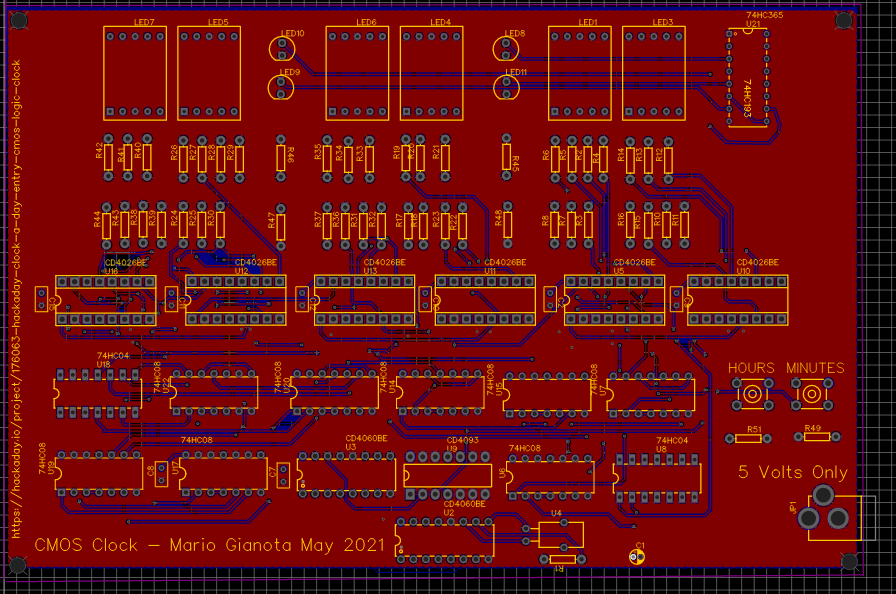
This is my entry into the informal Hackaday "Clock a day" project. A 7 Segment LED CMOS clock.
Already have an account? Log in.
To make the experience fit your profile, pick a username and tell us what interests you.
BOM_PCB_Retro CMOS Clock (20 ICs)_2021-05-23.csvBill Of Materials for the CMOS Clock.ms-excel - 3.26 kB - 05/23/2021 at 06:48 |
|
|
Gerber_PCB_Retro CMOS Clock (20 ICs).zipPCB Gerber files for the CMOS clock.x-zip-compressed - 378.76 kB - 05/23/2021 at 06:46 |
|
Gerber files and bill of materials released for the clock. See files section for download.
I found a horrible wiring bug that was preventing the hours digits from rolling over when they reached 24. Fixed.
I have one minor, or major concern depending on how you look at it: When I hooked up the 1 Hertz signal to a scope, the frequency displayed was 1.01 Hertz. I don't know if this was the fact that I was using a cheap scope ($50 from Amazon), or a cheap crystal, but I shall have to investigate further. I can't leave the clock running for too long without it freezing which is a result of a bad connection somewhere on the breadboard that I haven't managed to track down.
If anyone can think of a reason why the signal should be rated at 1.01 Hertz, I would be glad for some input, or pointers. Let me know in the comments section.
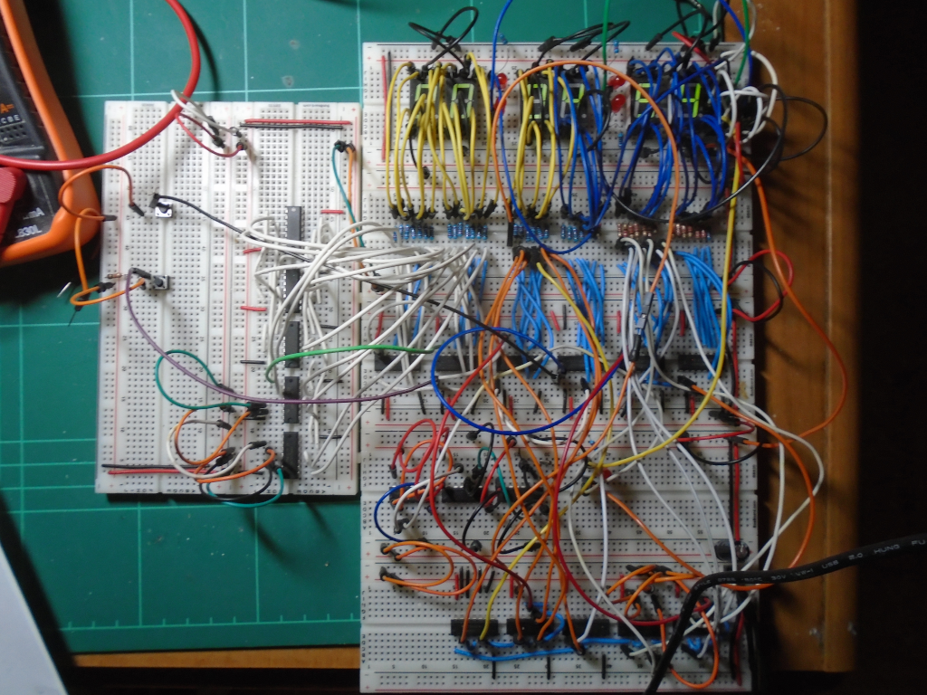
FInally finished the breadboard circuitry. The clock works fine. Now I can make a start on laying out the PCB. I uploaded the schematics (see images on right hand side).
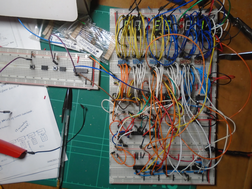
I just have the hours reset logic and the hours and minutes increment buttons to hookup. I ran into problems with my excessive use of jumper wires. I think the circuit was misbehaving due to bad connections and the inevitable inductance and stray capacitance problems that breadboards introduce to any circuit. Still, the clock is more or less working and I am fairly pleased with how it has turned out. My initial schematics that I drew up were approximately 75% correct; not bad a s a first guess, I suppose. I have changed the circuit quite considerably and the new schematics will be available for you to look at in a few days time.
I won't know how good a timekeeper it is until I build the PCB. I am afraid that the breadboard circuit is just too flaky for me to run a reliable timing test, but the logic works just fine. :)
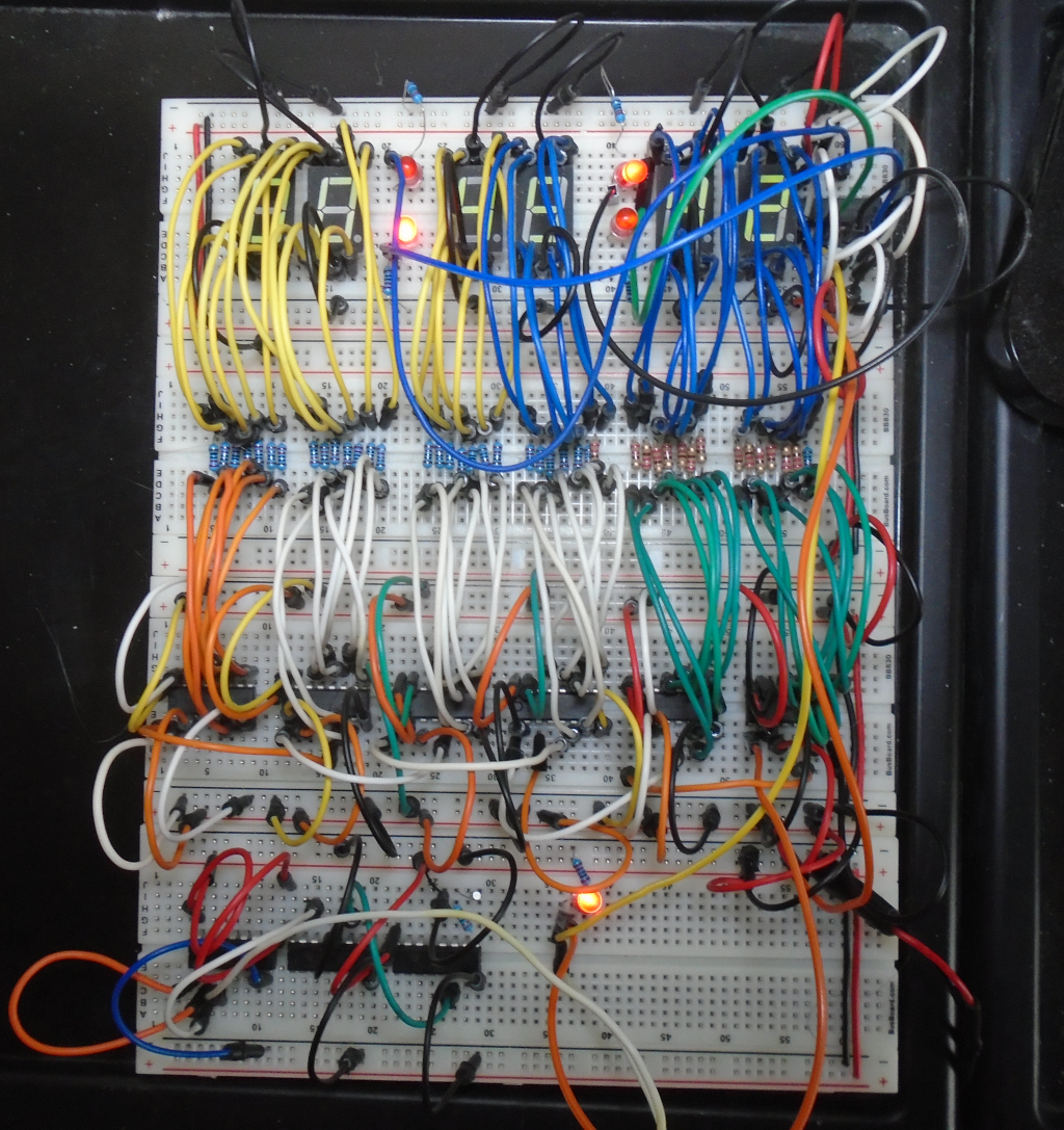
That's all of the 7 segment LEDs connected to their drivers and a 1 Hertz signal is being fed into the segment drivers. No logic yet, so all it does is to count seconds. Whilst I am waiting for ripple counters to arrive, I will implement the logic on an Arduino Uno and hook it up to the circuit.
I have the clock counting seconds. Next up, is to hookup the minutes and hours LEDs and then finally, add the counter reset control logic. 74HC393 counter chips are on order from AliExpress. In the meantime, whilst I am waiting for them to arrive, I will implement the logic on an Arduino Uno and connect it up to the circuit.
The LED blinkers were much too bright, so I have increased the resistance to 1K Ohms. They look much nicer now and don't hurt my eyes when I look at them.
I have discovered yet another error in the schematic. The crystal oscillator input to the 1 Hertz clock must be bounceless and noise free. The circuit amounts to an RC circuit consisting of a couple of resistors, a couple of tiny capacitors and the crystal itself. I have found the required circuit in a book written in the 1980s. I'll change the schematic as soon as I can and show you the correct circuit. I can't believe there is this much work in such a simple clock, but there is.
I am using the wrong kind of ripple binary counter (the CD4060BE in the schematic). I spent a frustrating day trying to find the fault with the breadboard hookup. Anyway, I eventually found the problem and have found a chip that will do what I expect it to do (I think it will, but you know how it is.). The supplier is in China so I will have to wait about 30 days for delivery. As soon as it arrives I will be able to quickly test the counter reset logic for hours, minutes and seconds. The new binary counter chip is a CD4020B. Despite this problem I am confident that the project is proceeding nicely.
The LED blinkers sit between the 7 segment LED displays and blink on and off at 1 Hertz. The circuit in the video tests them. They appear to be working fine (as far as I can tell). They are driven by a 74HC365 buffer chip that I purchased from Ebay at an extortionate cost. The top board provides the 1 Hertz clock signal to the buffer chip.
 Marten Electric
 Christian
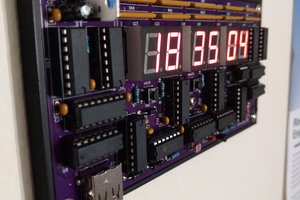
 Erik van Zijst
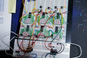
 dic3jam