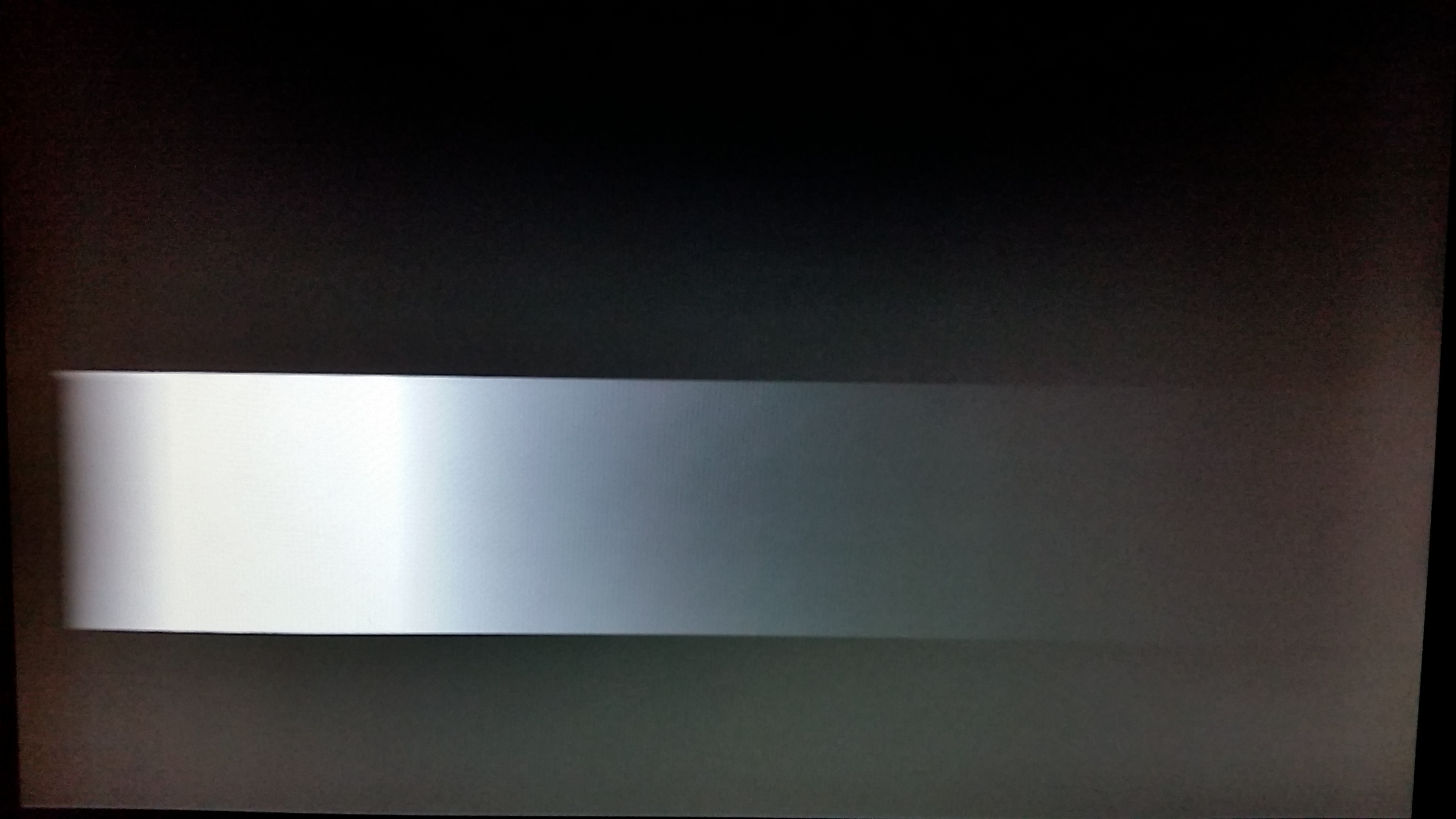
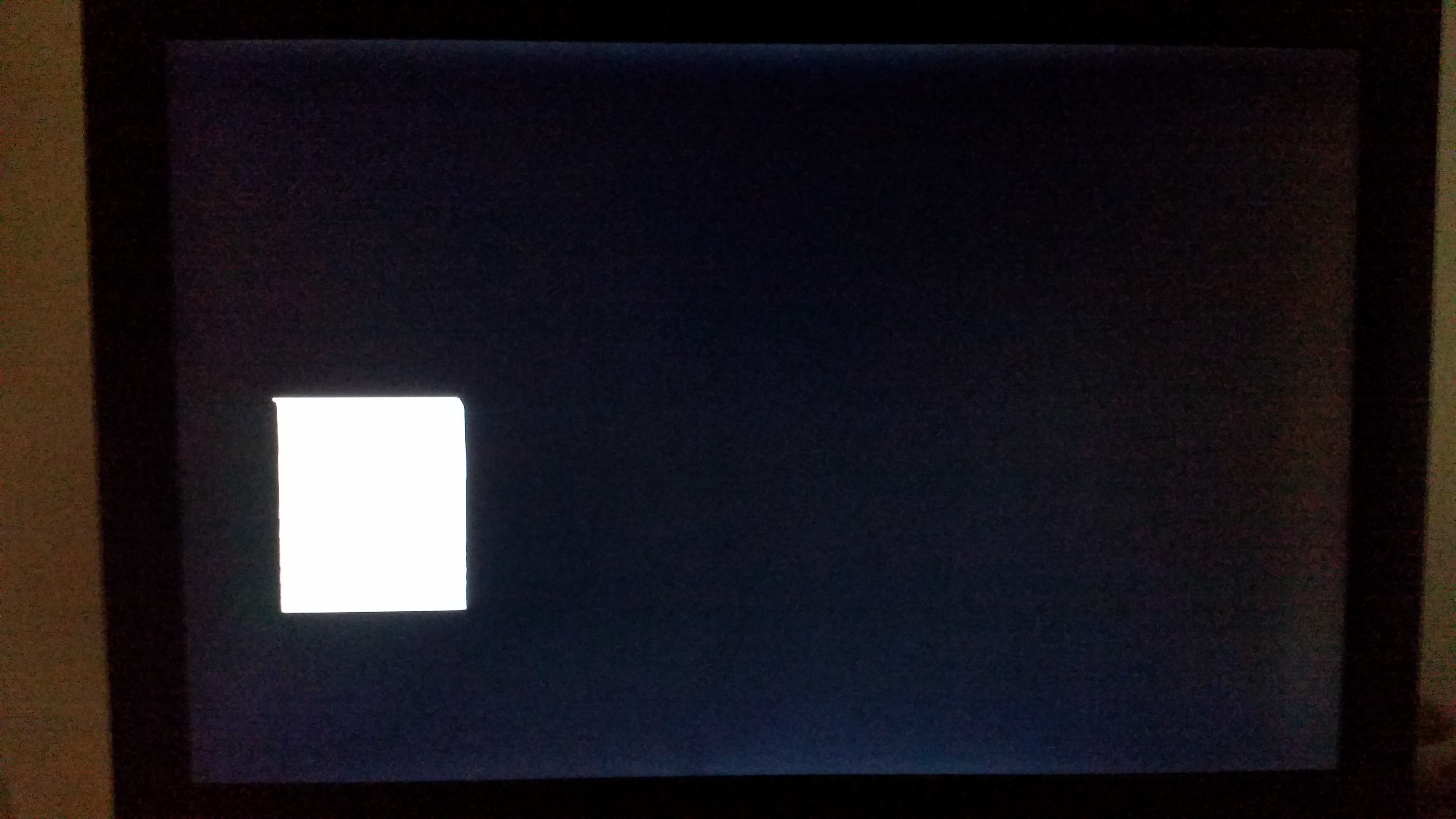
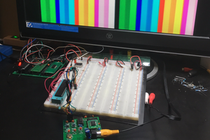
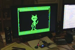
• It's been an interesting start with a curve ball or two thrown in

    mcu_nerd12/12/2020 at 01:45 0 comments

    I started my journey googling for details about the NTSC specifications and found this little gem here that helped quite a bit in getting me started out.  I first drew an image of alternating lines of black and white bars which surprisingly worked the first try. 

    My next step was to draw a box.  This is where I started running into problems. While the top and bottom edges were nice and clean, the edges on the sides were a bit fuzzy, as seen in the image below:

    I tried different resistor values between the DAC pin and the composite video jack.  I tried removing the resistor entirely and got this (I actually tried this after the fact that I found the problem.):

    After what I've observed, I started to turn my attention to the on-board DAC.  I dug into the datasheet and found that it stated that the DAC can operate of a speed "up to 140 ksps Conversion Rate." That sounded a bit too slow. I also searched in the electrical characteristics section of the datasheet and found that it stated a typical settling time of the DAC ranged from 7 to 10 microseconds depending on the supply voltage. some portions of the NTSC scanline are less than that.  From what I observed on-screen and from the datasheet, the DAC appears to be too slow for the job.  It looks like it's not transitioning fast enough from white back to black.  It could still very well be something I'm doing wrong.

    I then decided to try the method mentioned in the document I linked near the beginning of the post using two I/O pins and a few resistors for voltage dividers to create an extremely simple DAC. The result:

    A near-prefect image of a square! I fixed the slight distortion at the top of the square for an additional delay (result shown below.) 

    Now it was the time to focus on doing some pixels, and drawing some text with the pixels.  I created a huge array of bytes. I first did a checkerboard pattern with 8 bits per line (resulting image below):

    I then did an even larger array of bytes for 16 bits per line and did some test text and patterns (resulting image below):

    Another issue I've run into is that is that quite a bit of RAM is being consumed with making such large arrays. Last I checked I was using about 5K or RAM on the AVR64DA28 and it only has 8K of RAM.  I've read about techniques for storing such large arrays in flash as opposed to RAM, so I'll have to give that I try.  If anyone has any suggestions or comments (perhaps to yell at me for doing something wrong with the DAC), feel free to comment!