 Michael Gardi
How the Original Think-a-Tron Works
Before you can begin to understand how Think-a-Tron works, you need to see one actually running. This video does a great job of explaining how to operate a Think-a-Tron.
Having seen a Think-a-Tron in action, would you be surprised to learn that there are no active components? In fact, the only passive component is a single incandescent bulb powered by two D batteries! Think-a-Tron is actually a cleverly devised mechanical device. Let's see how it was done.
This is the back of the machine. The unit I purchased did not have a rear covering panel, but here is a photo of one.
 With the back cover removed you can see the first big reveal.
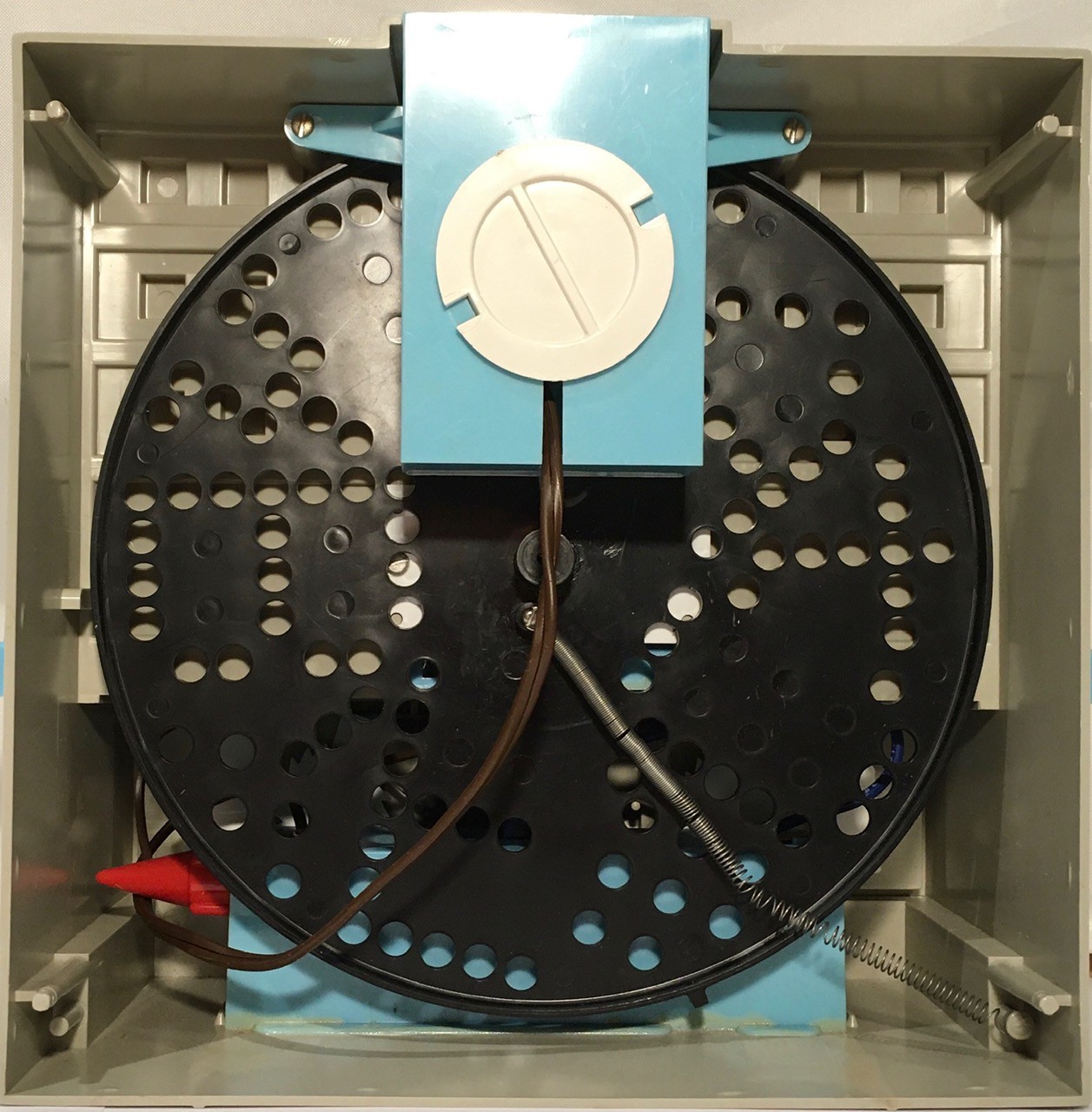
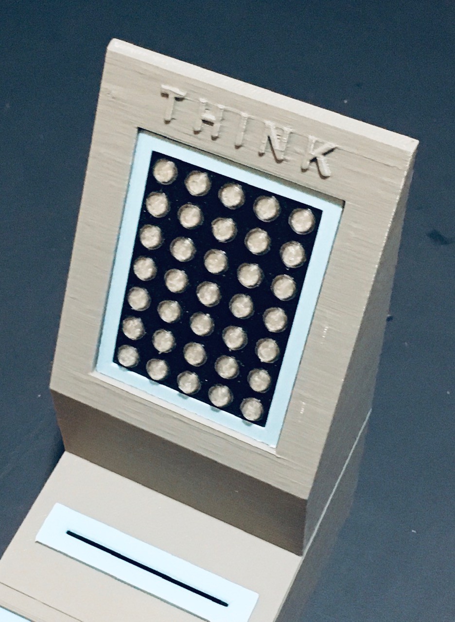
What I had assumed would be some sort of early "electronic" 5x7 matrix display, was actually just a spinning disk. In hindsight this makes sense. In 1960, LEDs are still a couple of years away. Add many more years on top of that until they would be cheap enough to be used in a product like this. Using 35 incandescent bulbs would have been a nightmare. But a spinning disk, a single incandescent bulb, and some clever diffusers, that was ingenious. IMHO, the blinking light effect achieved as Think-a-Tron is "calculating" the answer, which we had come to associate with large mainframe computers in the 60's, was outstanding.
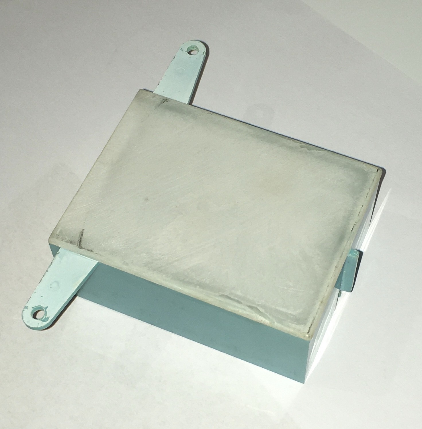
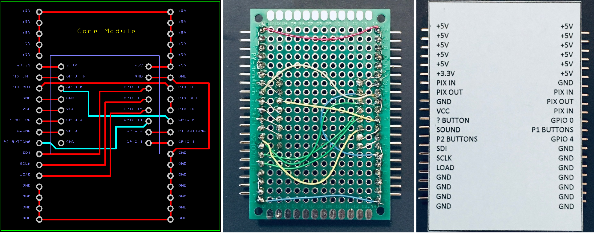
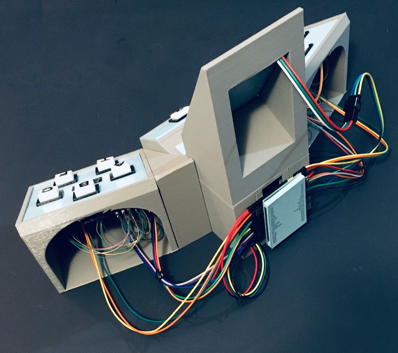
At the top, the blue box with the white "plug" holds the bulb.
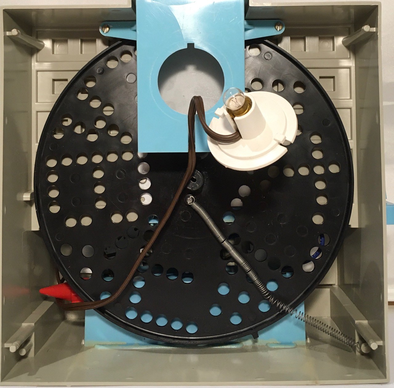
Removing the bulb box we can see the first white diffuser panel on its bottom side.
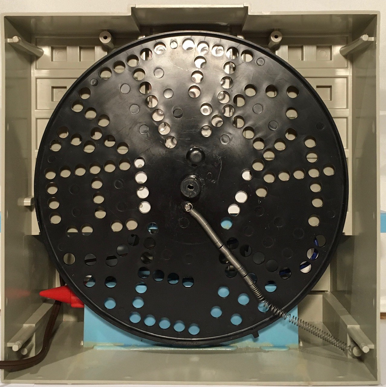
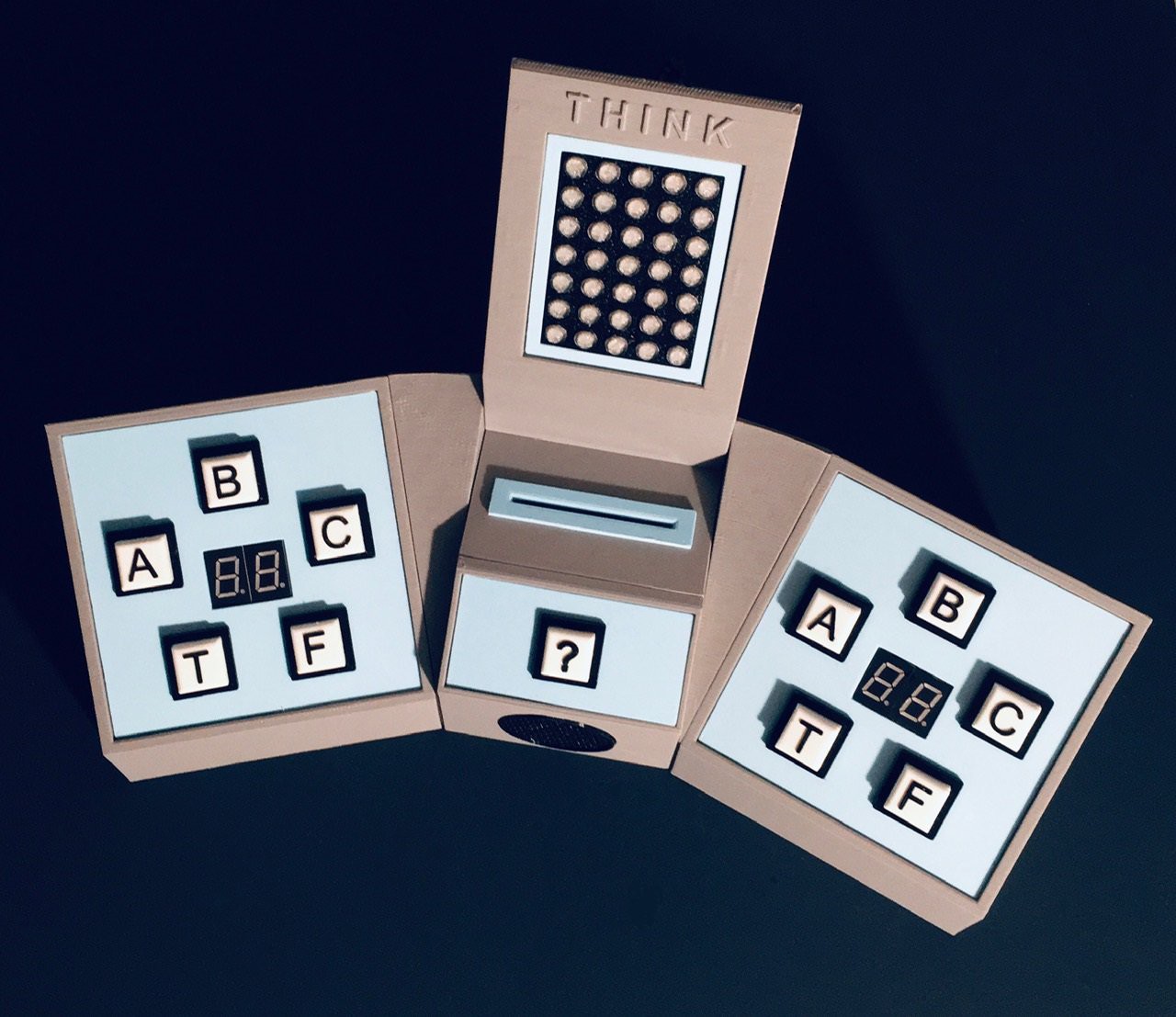
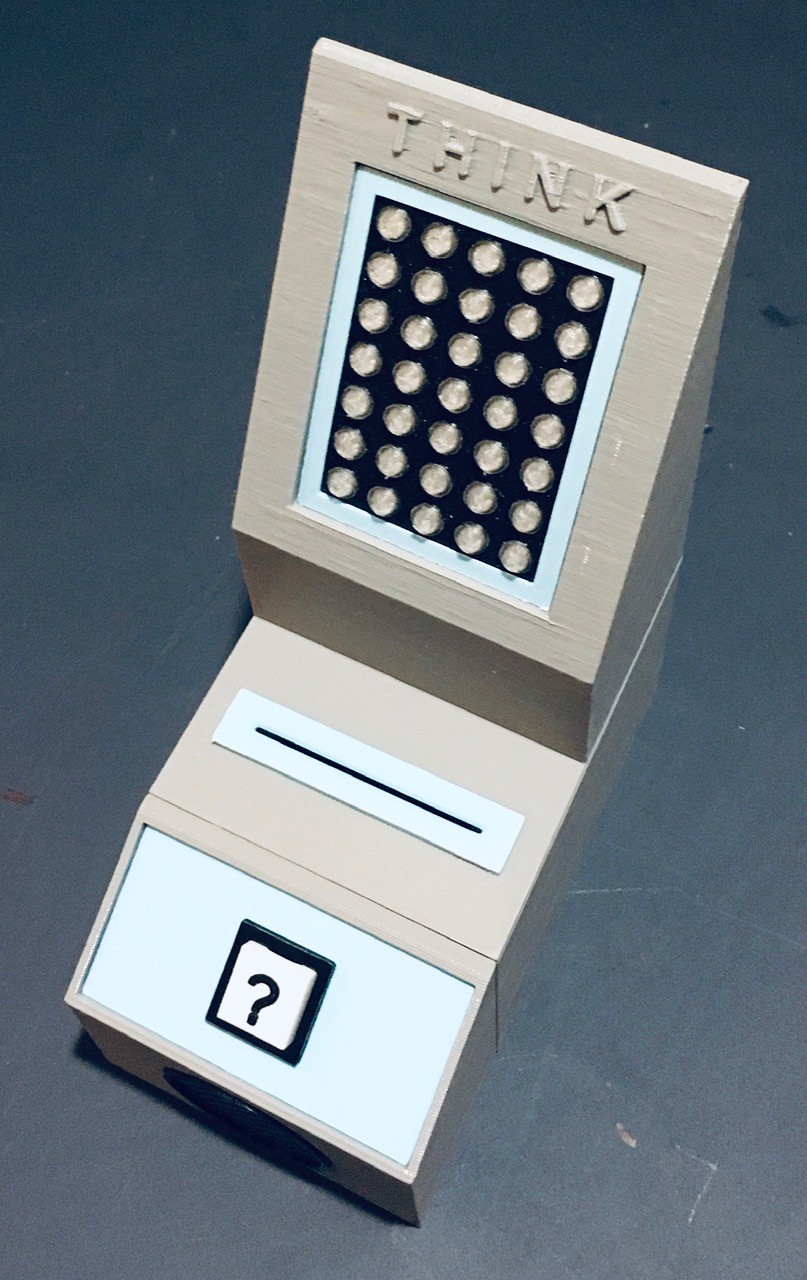
This also gives us a better look at the wheel. You can make out the 5 "answers" A, B, C, T, and F, as well as some random holes in between used to help "sell" the blinking light effect. Also notice the spring used to tension the wheel when "cranked" from the front.
Removing the display wheel exposes the secondary diffuser panel into which a 5x7 matrix of clear lenses is embedded (which of course line up with the holes in the display wheel).
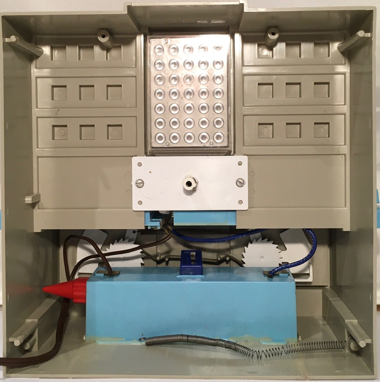
The white plate in the middle holds a central shaft in place. The crank handle in front of Think-a-Tron is connected to this shaft.
At the bottom, the blue box is a battery holder which is glued to the frame.
Behind the battery holder you can see the gears that make up the simple mechanical score counters. A downward press of the lever beside each of the two circular counters, turns the counting wheel clockwise, increasing the score by one .
This is what it the machine looks like with the shaft and plate removed. You can start to see a set of levers exposed.
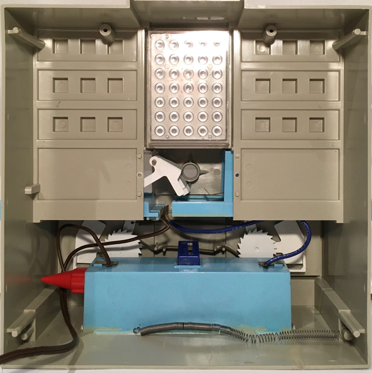
And here is the shaft.
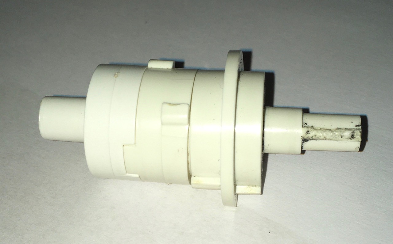
The crank handle is connected to the left side, and the display wheel to the right. Note the "bumps" sticking up from the central part of the shaft. We can see three of five answer tabs that are spaced equally both around the circumference, and the along the length, of the middle part of the shaft, to the left of a protruding ring. To the right of the ring you can see a single tab sticking up.
The "ridge" sticking up on the rightmost part of the shaft is "keyed" to a corresponding grove in the wheel's central hole.

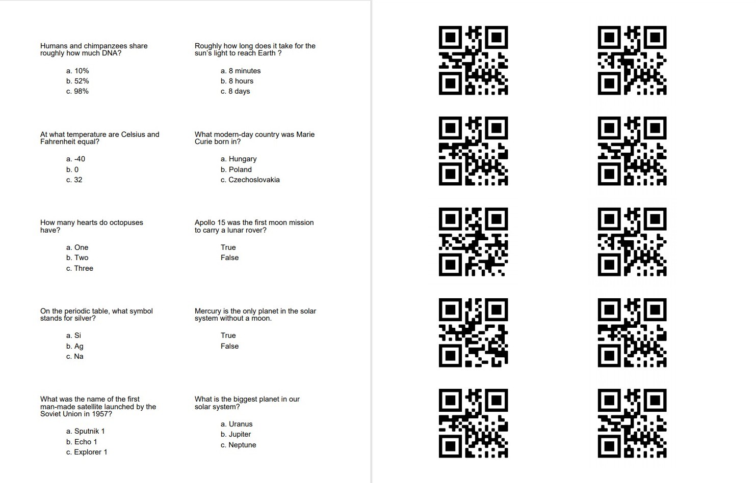
Now here is where the magic happens. As was mentioned in the video, the question cards have notches corresponding to the correct answers. The circular holes and cut corner are just for show.
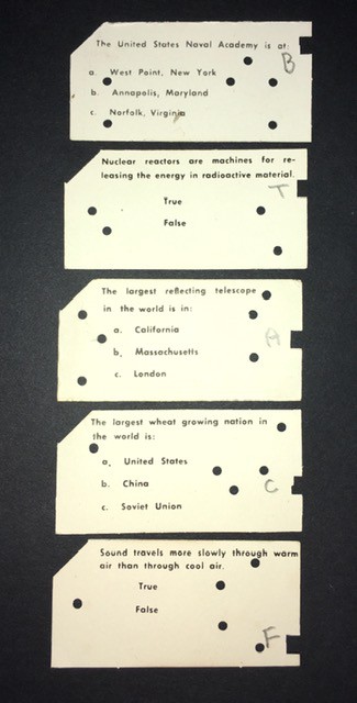
When a card is pushed into Think-a-Tron it will interact with the levers positioned beside the shaft.
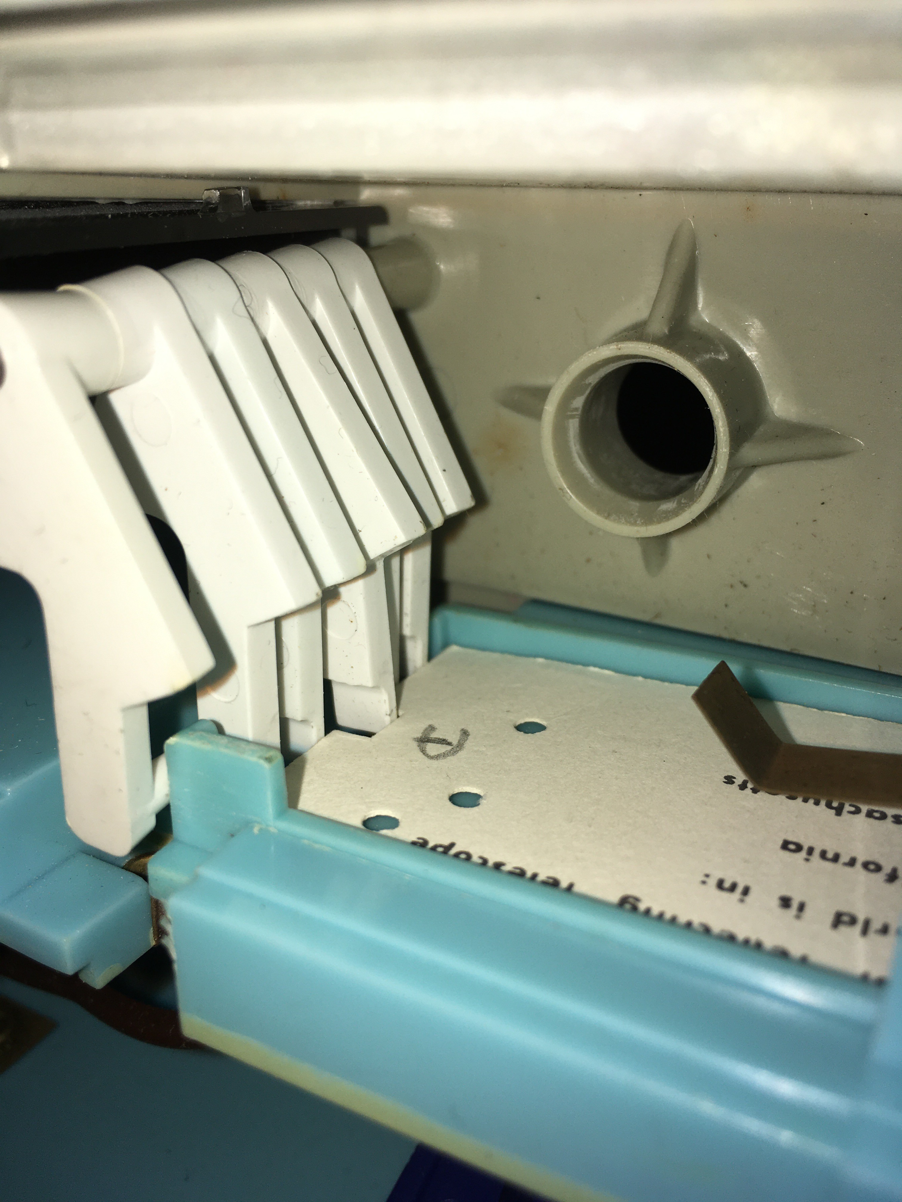
You can see in the photo above, that four of the five "answer" levers are pushed away by the card, allowing only the center lever (corresponding to the answer A) to protrude. As the display wheel turns, the middle bump on the shaft for answer A will hit the protruding lever, stopping the wheel. The sixth "rightmost" lever locks the spring tensioned display wheel in place when it is cranked, and releases the wheel to spin freely to the correct answer when the card is pushed in. You can see the card tray's blue tab pushing the lever...
Read more »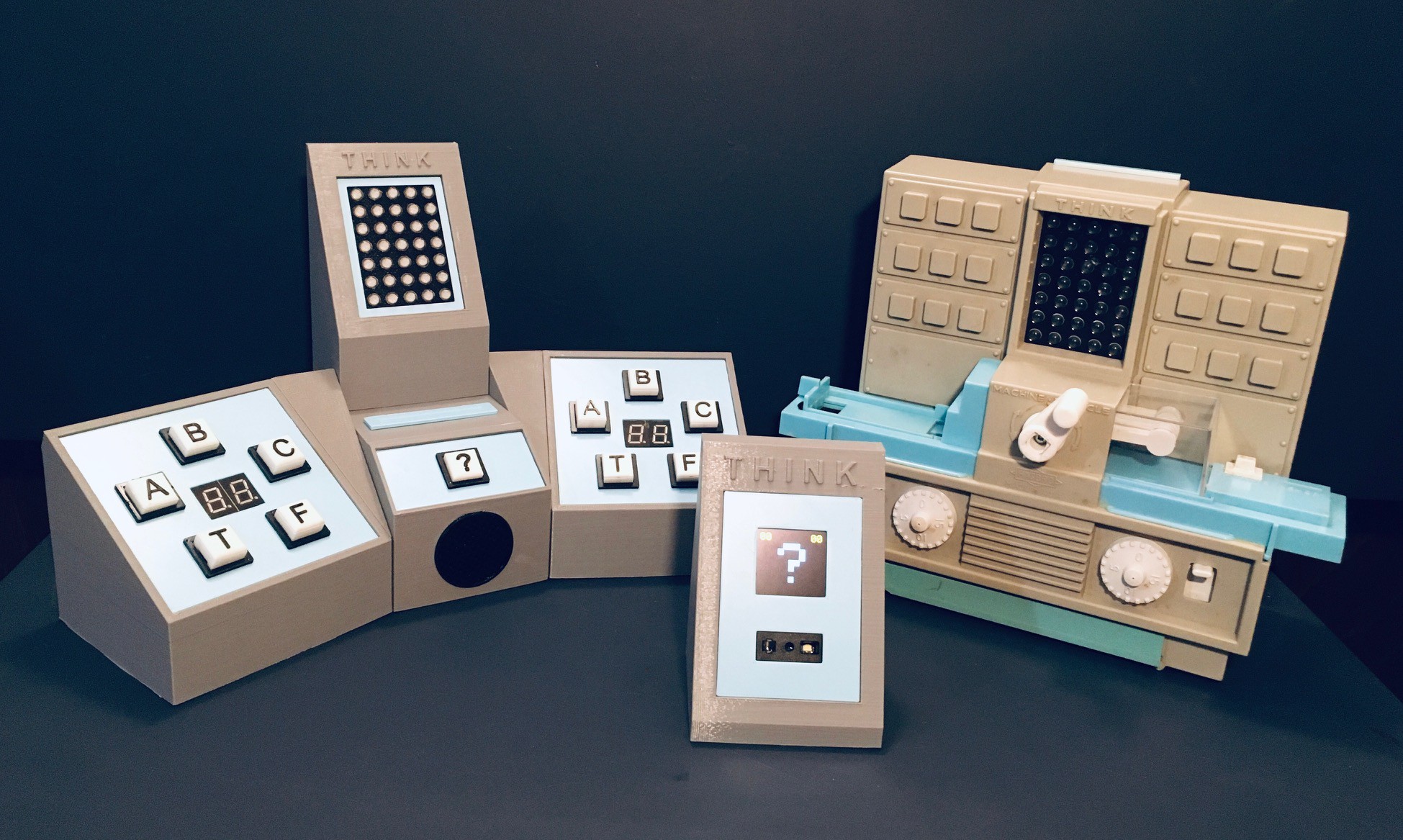


 David Boucher
 Beko Pharm
 Chris Gervang
.very cool project recreating retro tech ....compliments!......i saw such toy computer in the Science Museum in London back in 2017 ....it is listed but unfortunately no pictures: https://collection.sciencemuseumgroup.org.uk/objects/co492323/think-a-tron-electronic-question-and-answer-computer-computer-educational-toy-model