 Michael Gardi
How the Original Think-a-Tron Works
Before you can begin to understand how Think-a-Tron works, you need to see one actually running. This video does a great job of explaining how to operate a Think-a-Tron.
Having seen a Think-a-Tron in action, would you be surprised to learn that there are no active components? In fact, the only passive component is a single incandescent bulb powered by two D batteries! Think-a-Tron is actually a cleverly devised mechanical device. Let's see how it was done.
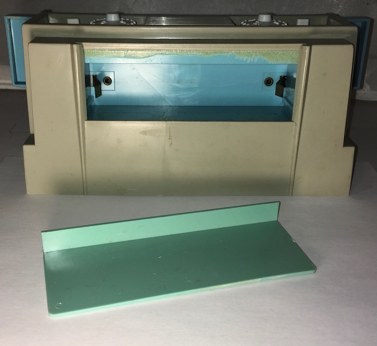
This is the back of the machine. The unit I purchased did not have a rear covering panel, but here is a photo of one.
 With the back cover removed you can see the first big reveal.
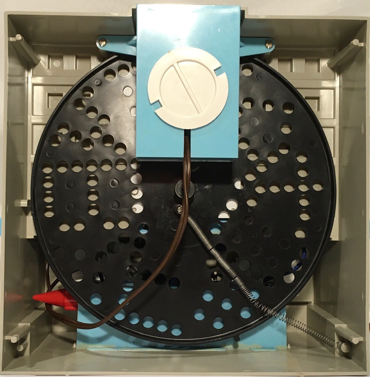
What I had assumed would be some sort of early "electronic" 5x7 matrix display, was actually just a spinning disk. In hindsight this makes sense. In 1960, LEDs are still a couple of years away. Add many more years on top of that until they would be cheap enough to be used in a product like this. Using 35 incandescent bulbs would have been a nightmare. But a spinning disk, a single incandescent bulb, and some clever diffusers, that was ingenious. IMHO, the blinking light effect achieved as Think-a-Tron is "calculating" the answer, which we had come to associate with large mainframe computers in the 60's, was outstanding.
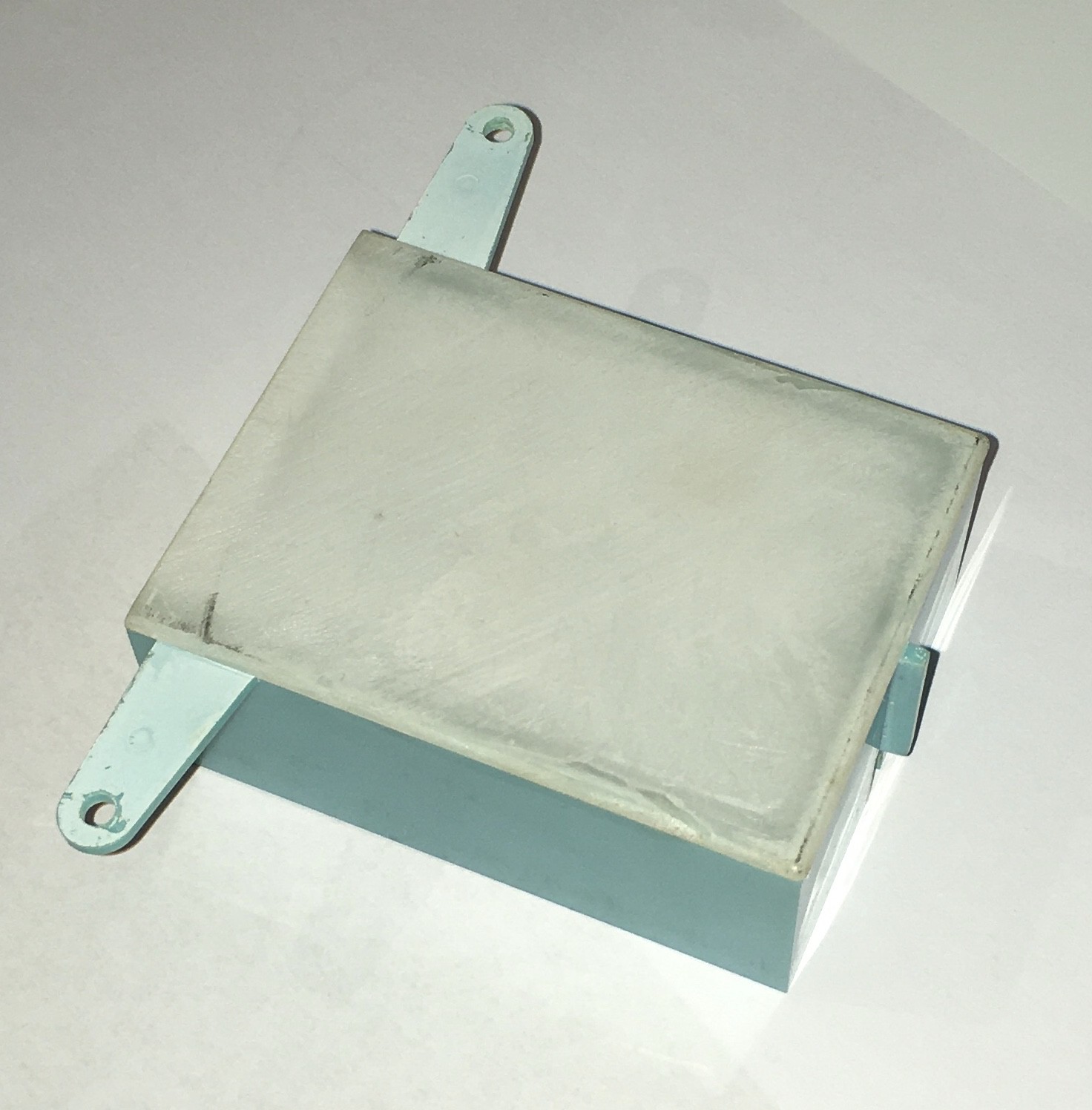
At the top, the blue box with the white "plug" holds the bulb.
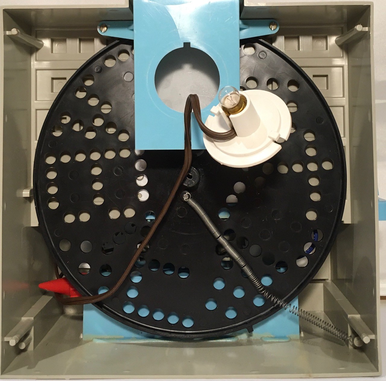
Removing the bulb box we can see the first white diffuser panel on its bottom side.
This also gives us a better look at the wheel. You can make out the 5 "answers" A, B, C, T, and F, as well as some random holes in between used to help "sell" the blinking light effect. Also notice the spring used to tension the wheel when "cranked" from the front.
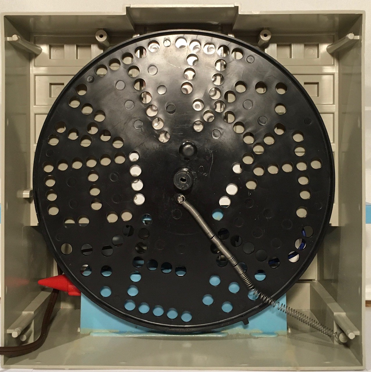
Removing the display wheel exposes the secondary diffuser panel into which a 5x7 matrix of clear lenses is embedded (which of course line up with the holes in the display wheel).
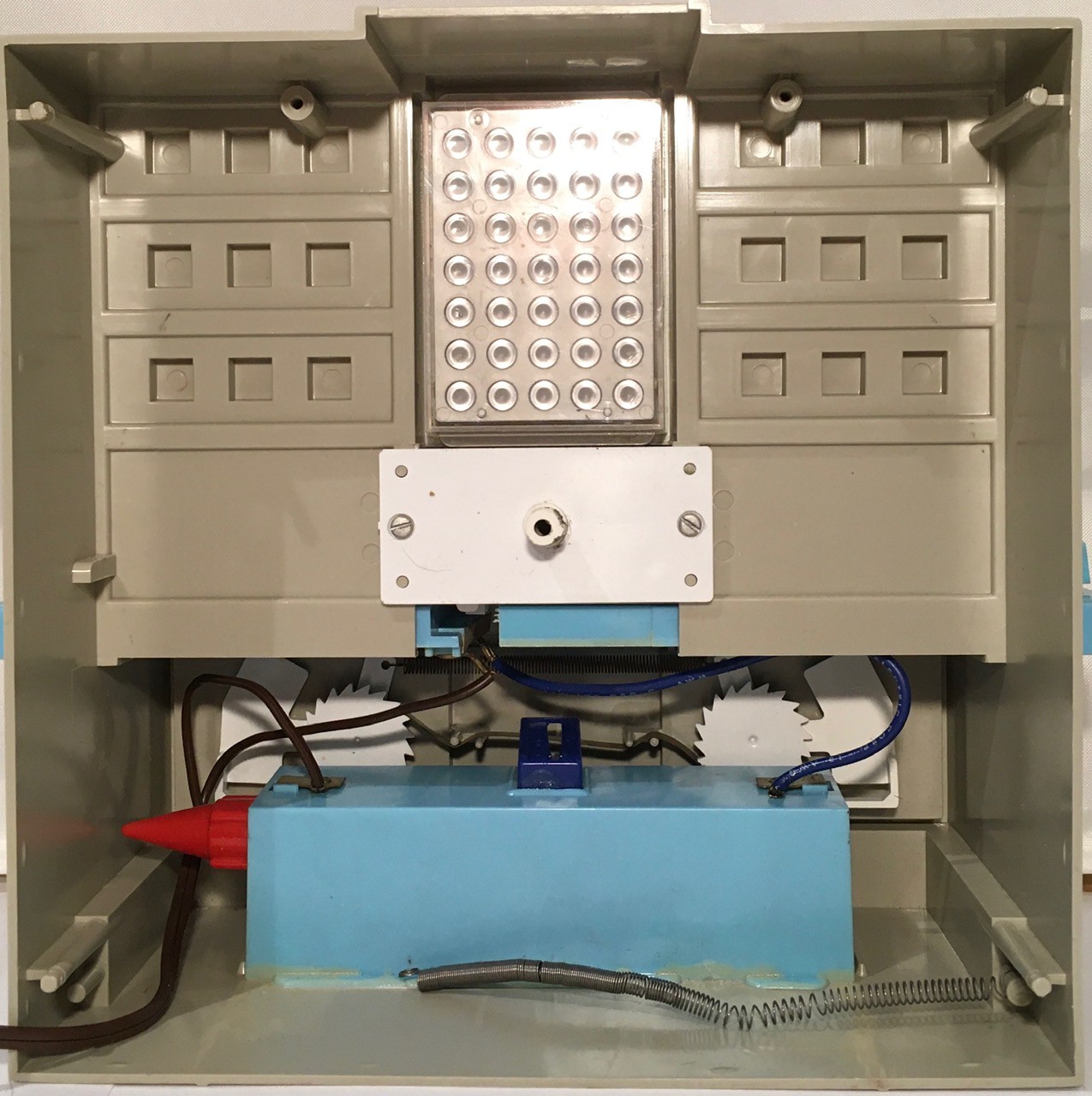
The white plate in the middle holds a central shaft in place. The crank handle in front of Think-a-Tron is connected to this shaft.
At the bottom, the blue box is a battery holder which is glued to the frame.
Behind the battery holder you can see the gears that make up the simple mechanical score counters. A downward press of the lever beside each of the two circular counters, turns the counting wheel clockwise, increasing the score by one .
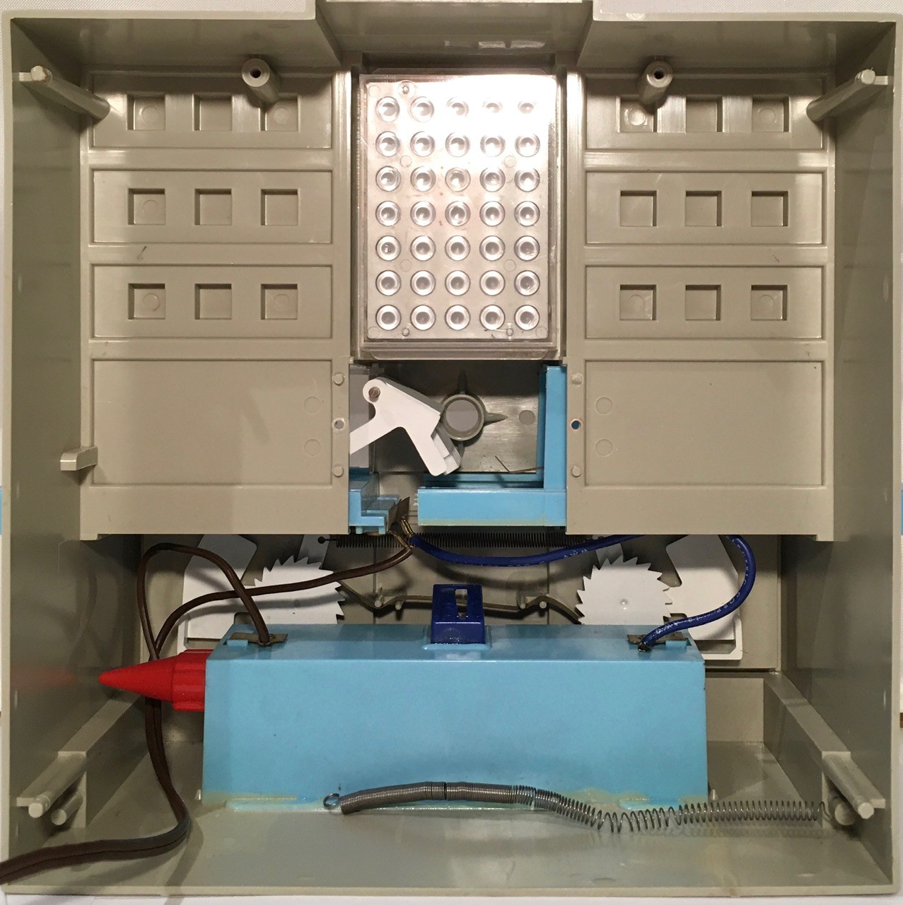
This is what it the machine looks like with the shaft and plate removed. You can start to see a set of levers exposed.
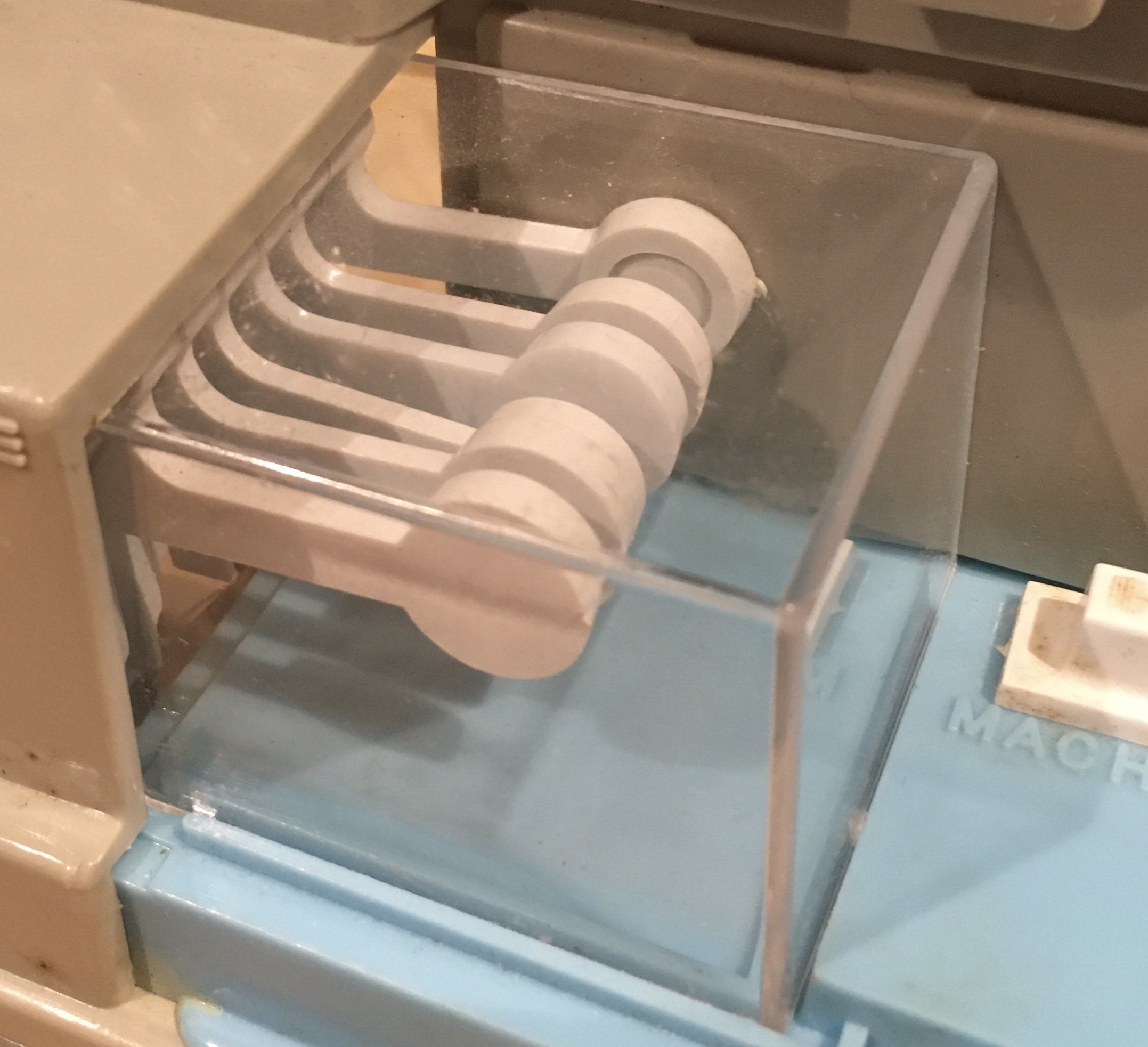
And here is the shaft.
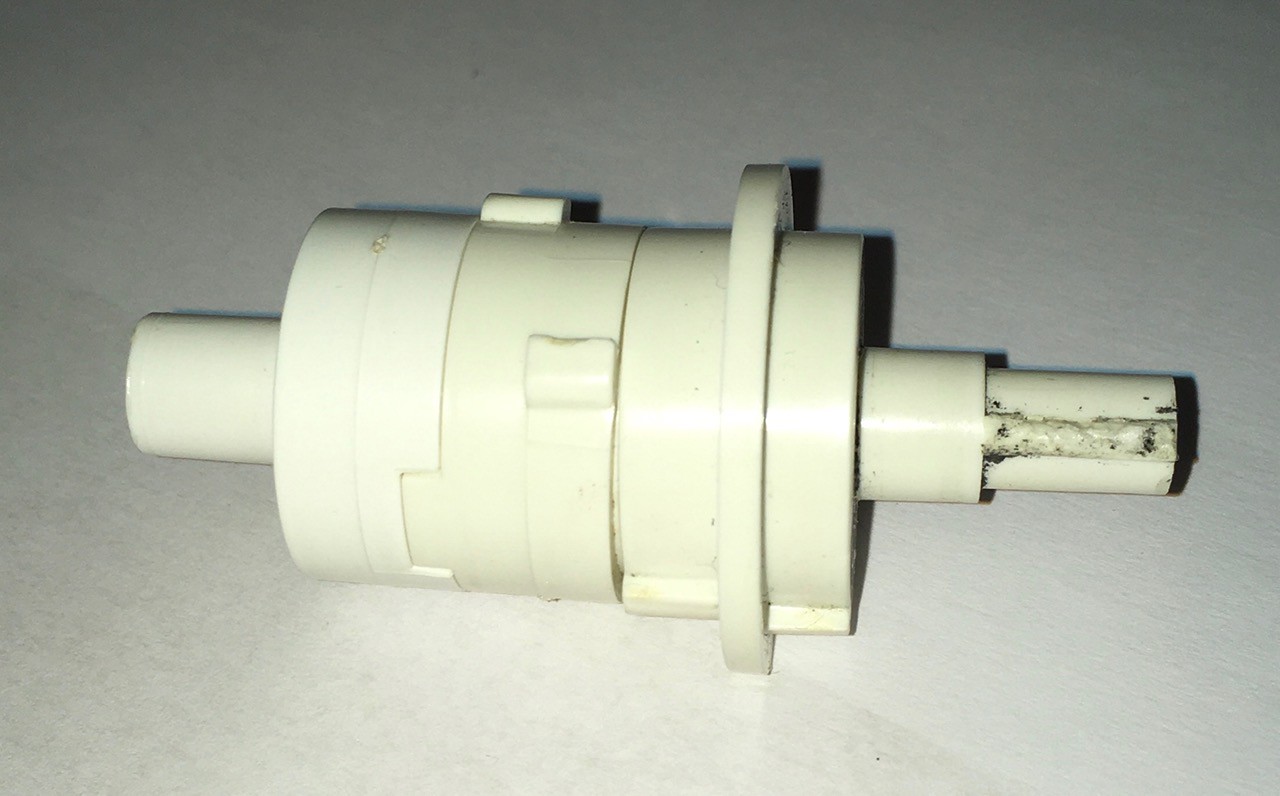
The crank handle is connected to the left side, and the display wheel to the right. Note the "bumps" sticking up from the central part of the shaft. We can see three of five answer tabs that are spaced equally both around the circumference, and the along the length, of the middle part of the shaft, to the left of a protruding ring. To the right of the ring you can see a single tab sticking up.
The "ridge" sticking up on the rightmost part of the shaft is "keyed" to a corresponding grove in the wheel's central hole.

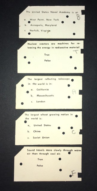
Now here is where the magic happens. As was mentioned in the video, the question cards have notches corresponding to the correct answers. The circular holes and cut corner are just for show.
When a card is pushed into Think-a-Tron it will interact with the levers positioned beside the shaft.
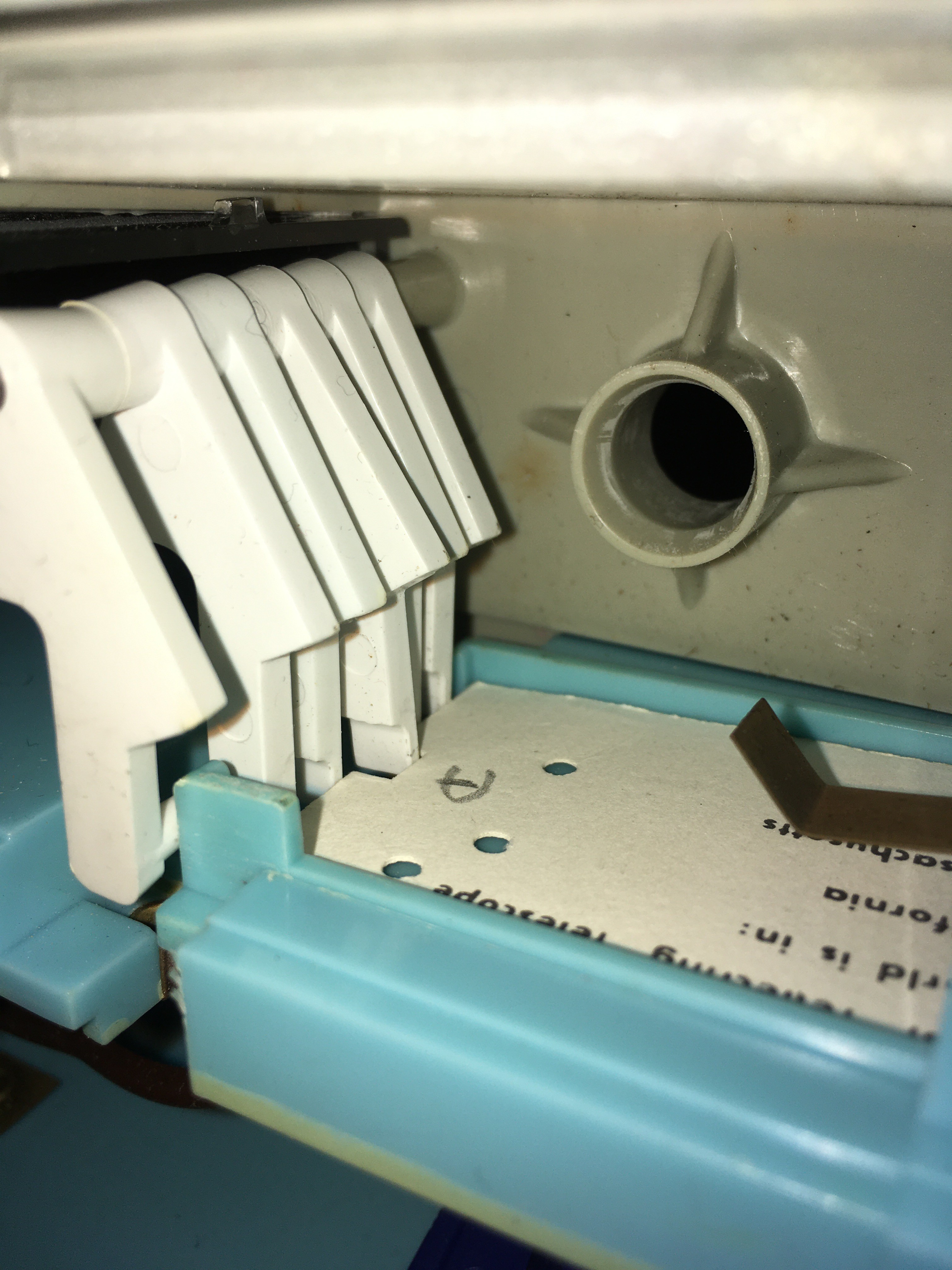
You can see in the photo above, that four of the five "answer" levers are pushed away by the card, allowing only the center lever (corresponding to the answer A) to protrude. As the display wheel turns, the middle bump on the shaft for answer A will hit the protruding lever, stopping the wheel. The sixth "rightmost" lever locks the spring tensioned display wheel in place when it is cranked, and releases the wheel to spin freely to the correct answer when the card is pushed in. You can see the card tray's blue tab pushing the lever into the release position in the photo above.
Finally check out the lever counterweights in this photo (the instruction manual calls them Fingers).
Not only do these provide an interesting visual element to the Think-a-Tron look, they ensure that the levers will always be pushed towards the central shaft.
For completeness here is a picture of the battery holder, as seen from below.
So that's how Think-a-Tron worked. A simple but clever mechanical contraption that "simulated" a computer of the day. In my mind it was a pretty damn cool hack.
Now it's my turn to take a computer, many orders of magnitude more powerful than anything available in 1960, and emulate the functionality of a simple mechanical device of the era. A much easier task I should think.
Let There Be Lights
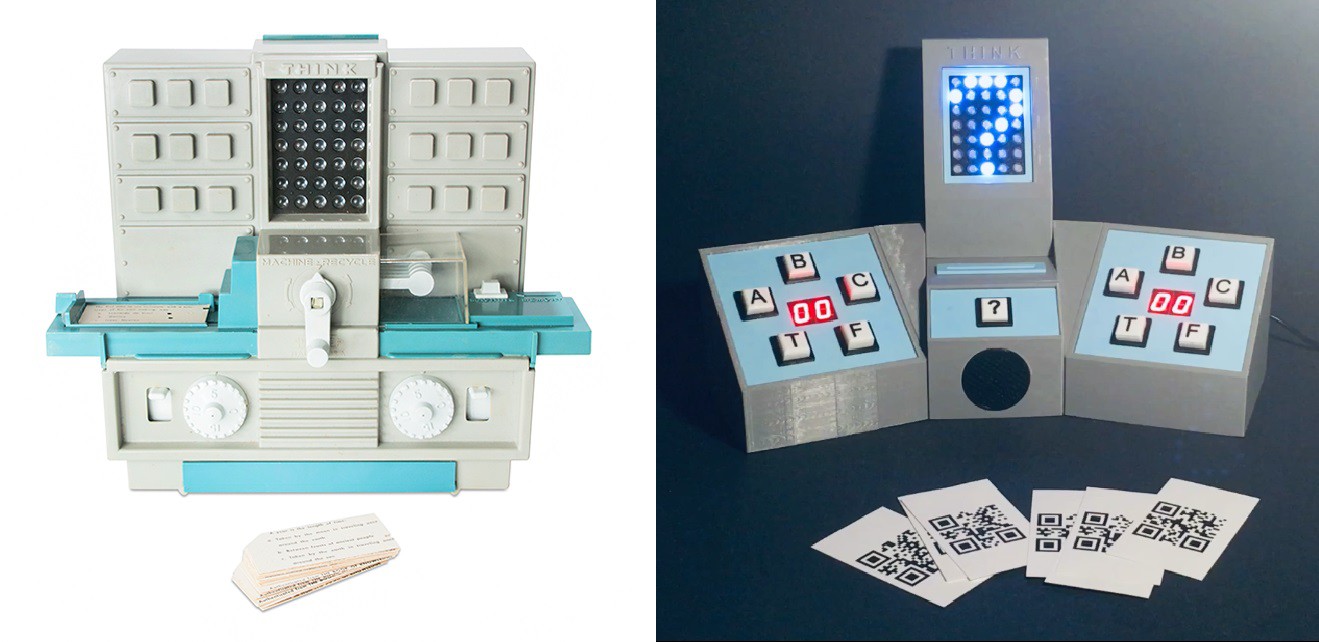
So I set about making the "Answer Panel" for my Think-a-Tron 2020. Here is what the original looks like.
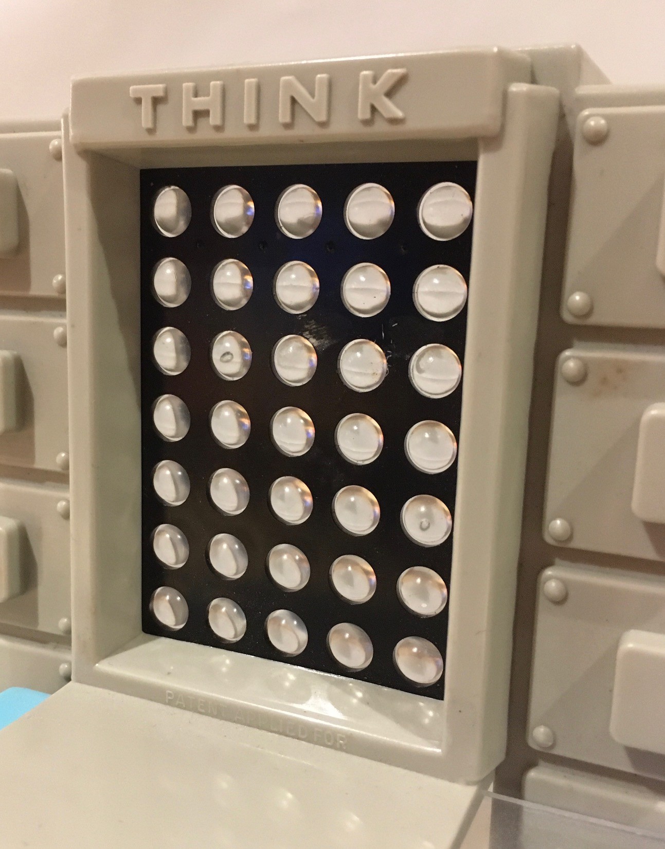
I was so impressed with the spinning wheel implementation of the original, that for a while I considered doing something similar, but motor driven perhaps. At the end of the day though I decided to replace what I initially thought was an LED array with an actual 5x7 LED array.
The panel on the original is 50 mm (2") wide and 70 mm (2 3/4") high and I wanted mine to be the same size. I searched for a suitably sized LED array but came up empty. I was about to start creating a custom PCB when I found these:
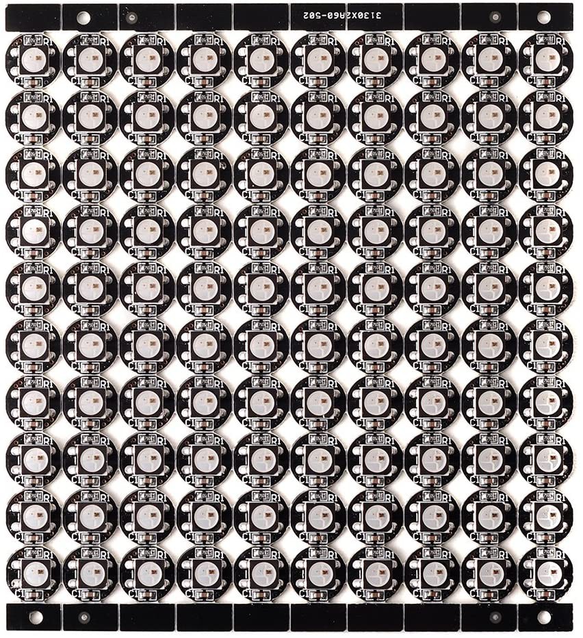
NeoPixel compatible, WS2812B addressable, smart RGB LED pixel lights. They are individual units but ship attached in a 10x10 grid as can be seen in the picture above. The good news for me is that each pixel light is about 10 mm in diameter which is perfect for my purposes. With a little careful bending it was easy to snap off a 5x7 block of these. As shipped they are not connected so I had to wire the individual units in my 5x7 array together.
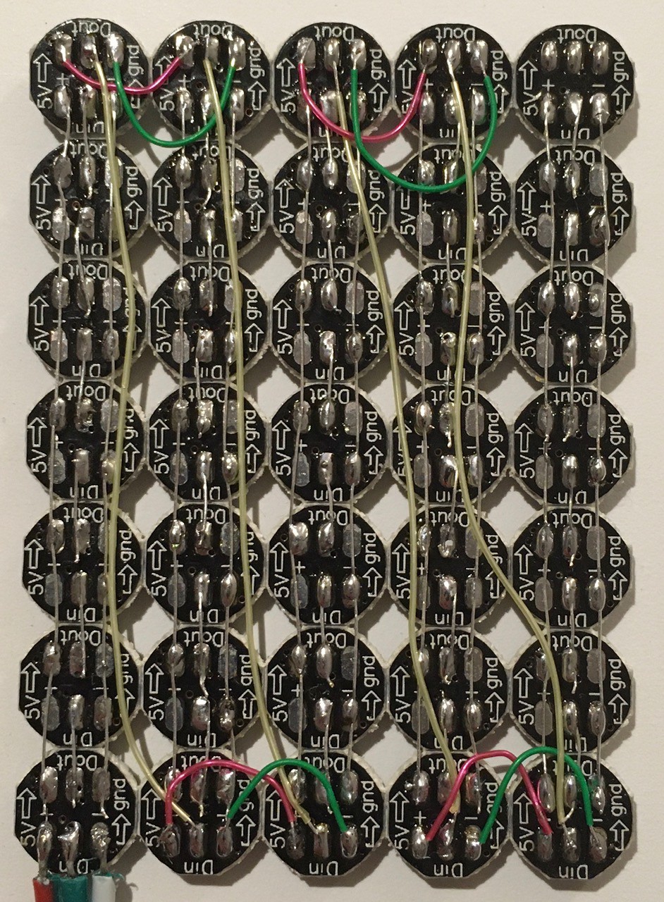
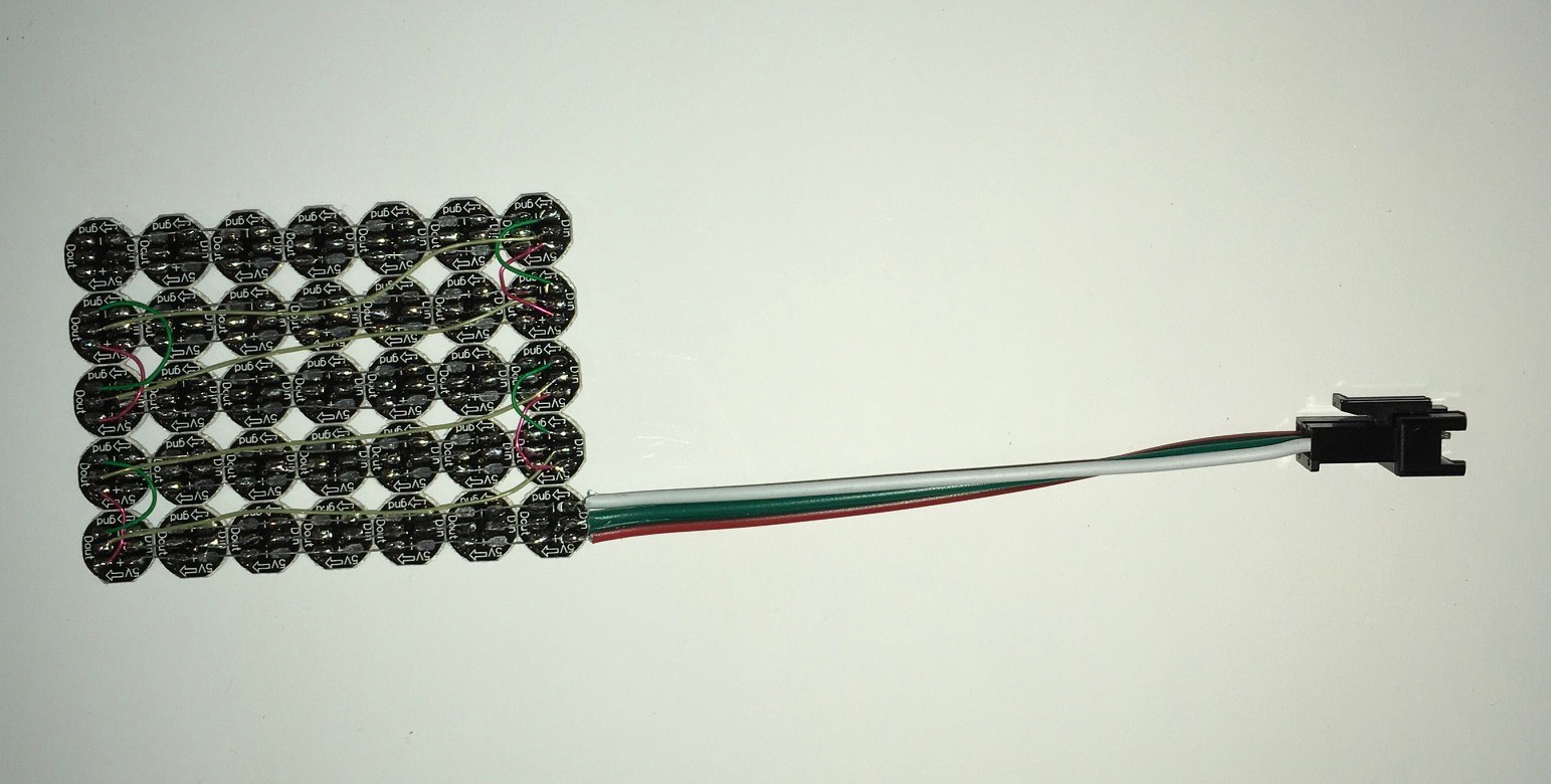
I used some 30 awg "wire wrapping" wire that I had lying around from the old days ;-) It was a lot of pads to wire but not too hard. The pixel lights shipped with a three wire connector that I attached.
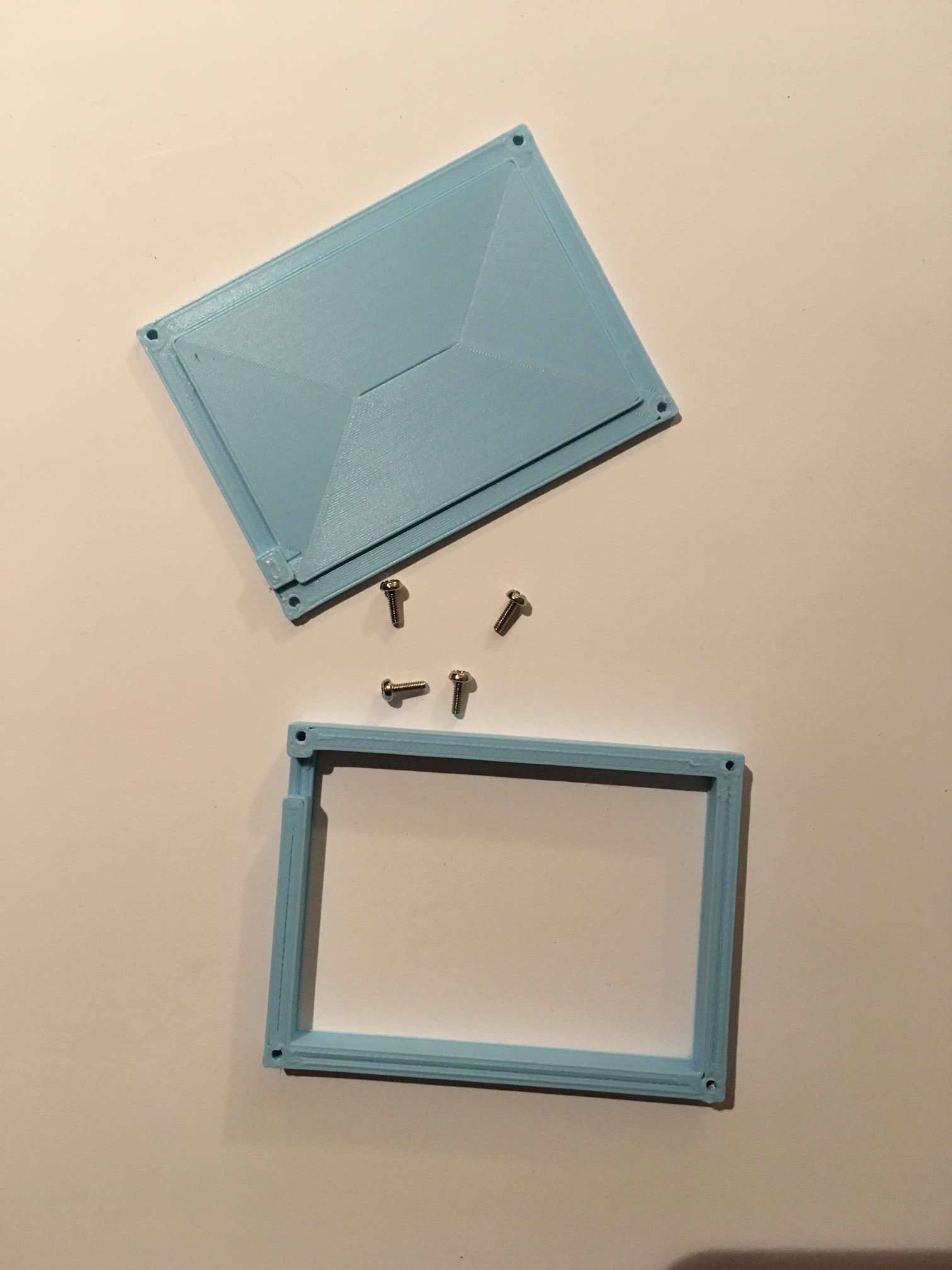
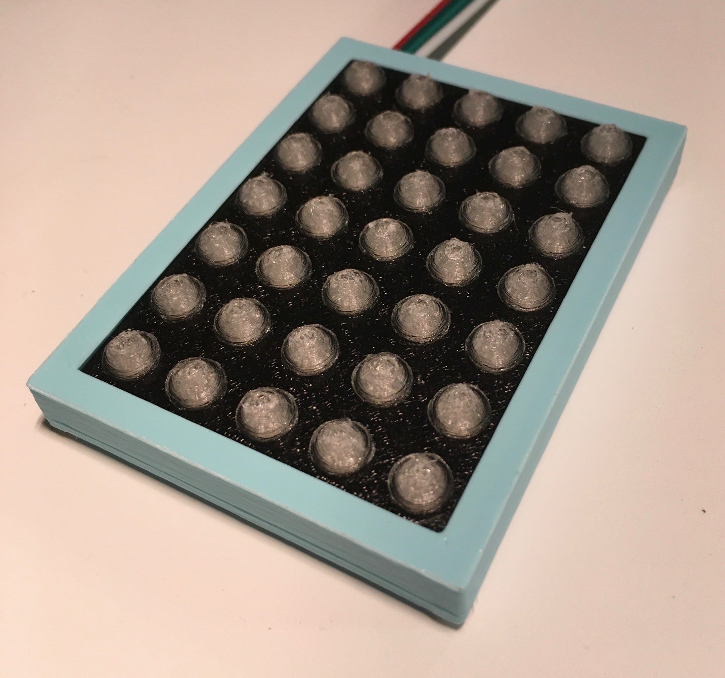
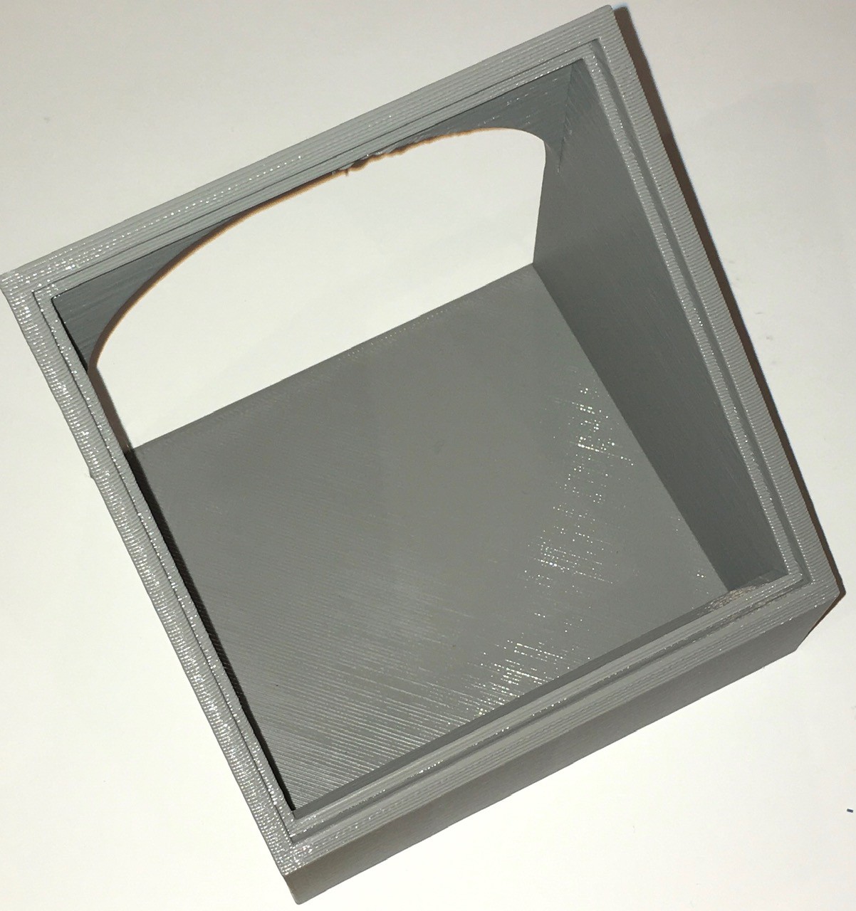
The next order of business was to make a diffuser for the lights. This is what I came up with.
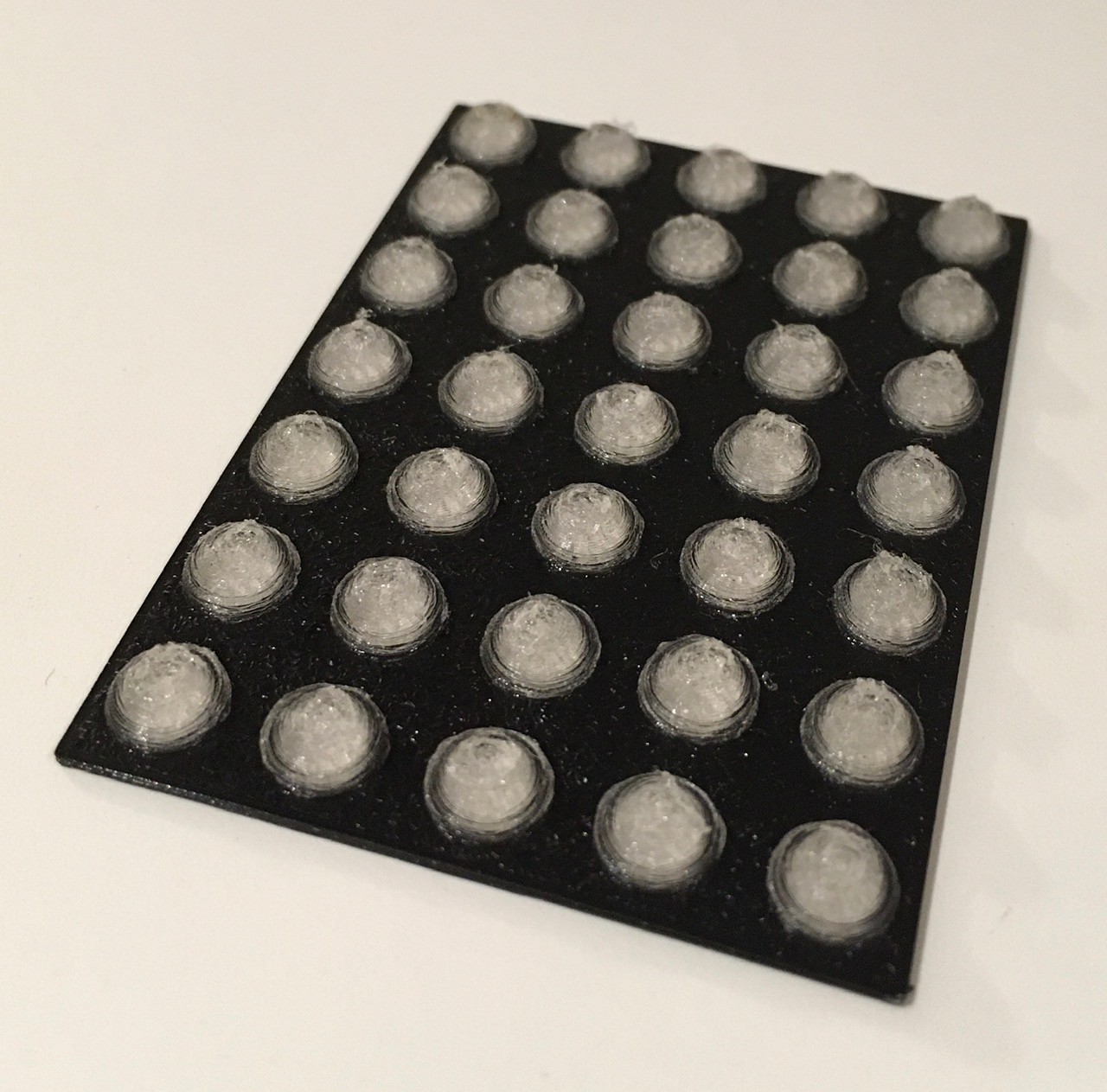
It's all one piece. I printed the black backing panel, paused the print, then finished with some "transparent" PLA filament. Not quite as clear as the original, but it gets the job done.
I printed a case.
And when it was all put together here is what it looked like.
Trivia Card Pursuit
Trivia cards for the original Think-a-Tron were pretty small at just 1 1/4 x 2 1/2 inches.
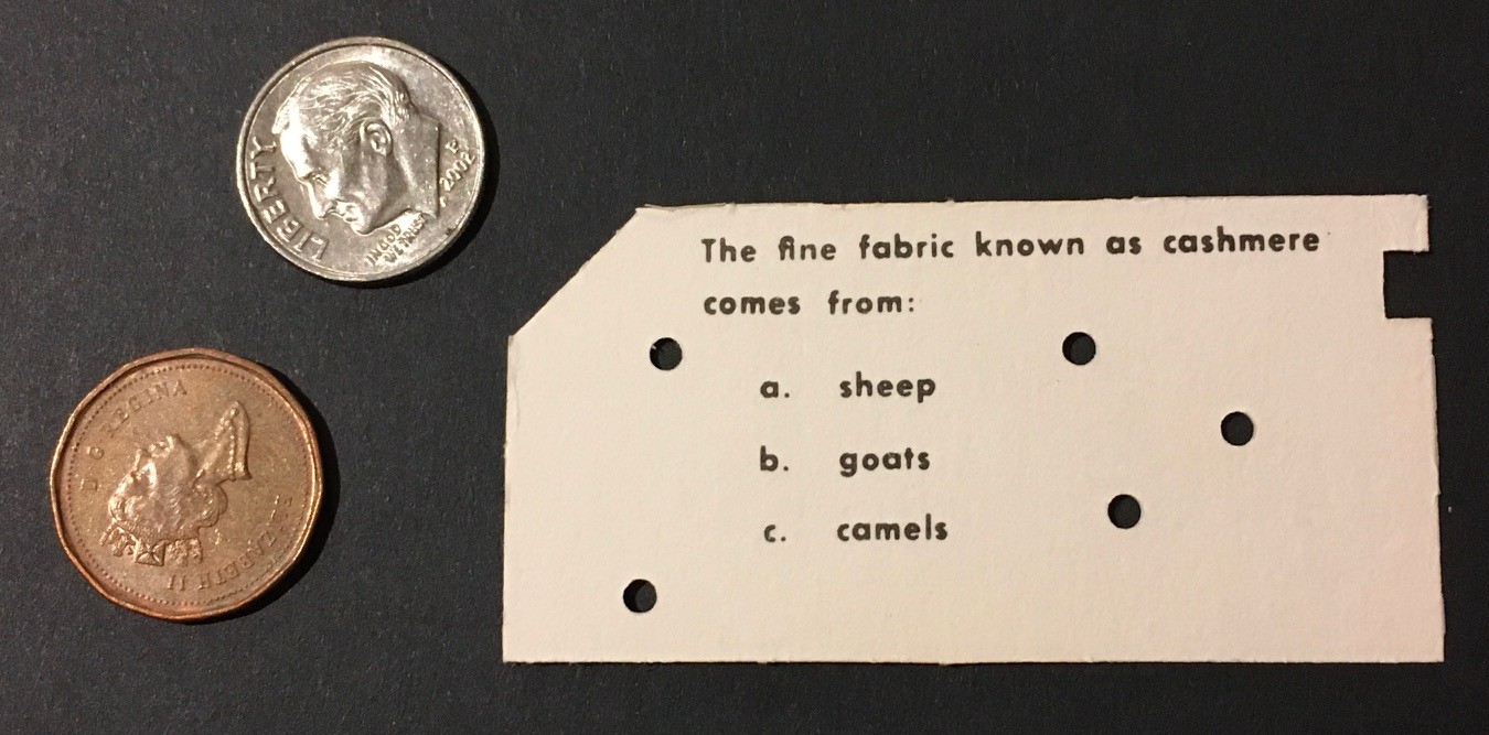
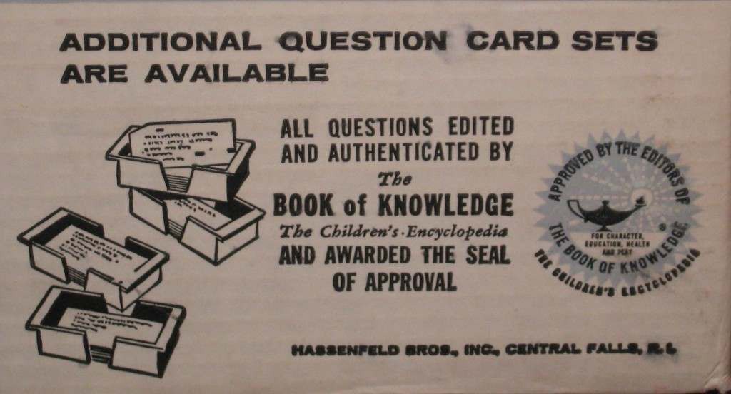
As has been mentioned, the punched holes and corner cut were just for show, only the notch on the right mattered. I wonder how long it took the kids "playing" Think-a-Tron to figure this out? The cards were also two sided. 150 cards (300 questions) shipped in the box. Additional sets of 50 cards (100 questions) on specific topics like sports could be purchased separately.
I had to decide what kind of cards to use for Think-a-Tron 2020. Some criteria:
- The answer had to be part of the question card and should not be too easy to figure out, like the "notch" was.
- I needed to be able to somehow "read" the answer from the card.
- The trivia cards should be easy for anyone to create.
After considering this for a while, I settled on the following:
- Think-a-Tron 2020 trivia cards will use a standard business card format of 3 1/2 x 2 inches. I chose this size because blank card stock and word processing templates are readily available. The larger size will also allow for more easily readable questions (old eyes).
- Questions will appear on the front of the card, and answers on the back, so only a single question per card.
- Answers will be encoded as QR codes. I considered bar codes but I think that QR codes are cooler looking.
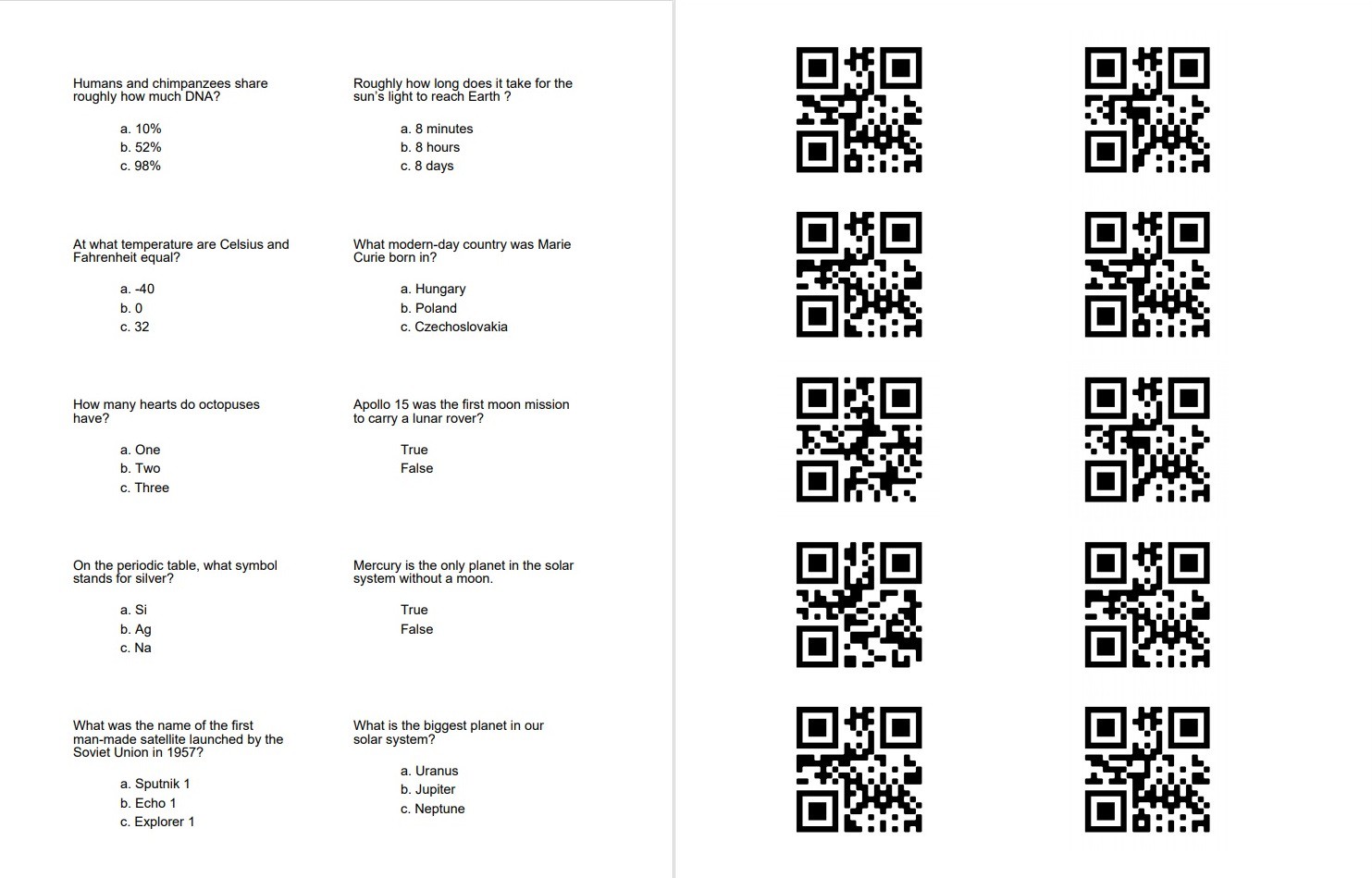
So I purchased some blank business card stock (Avery 5371) and using MS Word with the Avery template created some test cards. Seen here are the front of the printed sheet on the left and back on the right.
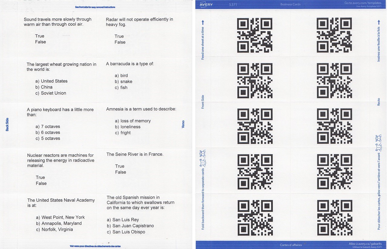
The QR codes were created online at the QR Code Generator site. I created one QR code image for each of the possible answers (A, B, C, T, F). It should be noted that it is still possible at this point to figure out the correct answer by looking carefully at the QR code. This is because the "payload" for each is just a single letter. My plan is to write an application to automate the creation of these cards at which time I will obfuscate the payload by adding some random "noise" to each answer.
So I ripped along the dotted lines and viola I have a small test deck of trivia cards to work with.

And the Answer Is...
The Hardware
I did a fair amount of research before I decided to use QR codes to encode my answers. I discovered that there was a lot of activity around using the ESP32-CAM module to read QR codes.
The ESP32-CAM is a very small camera module that combines an ESP32-S chip with an OV2640 camera that sells for about $10.
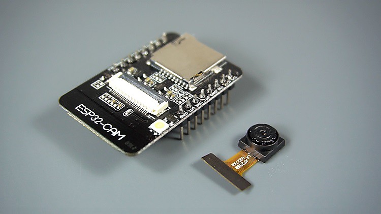
Since I needed an MCU for this project anyway this seemed like a good fit. Once the ESP32-CAM is programmed, and assuming that the built-in microSD slot is not used, there are 10 I/O pins available for general use. Notice that there is no USB port. Programing the ESP32-CAM requires an FTDI programmer.
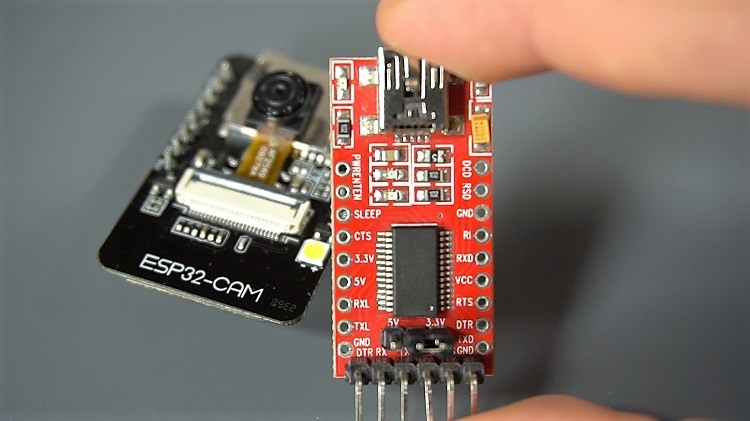
I bought a "bundle" that included the ESP32-CAM with OV2640 camera installed, an FTDI programmer, and a 40 pin bundle of female/female jumper wires for about $15 US off of Amazon.
I won't go into details here, but you can click this link for a great tutorial on setting up the ESP32-CAM. I followed these instructions and got the Video Streaming Server working easily. Pretty cool stuff.
The Software
If you google "ESP32-CAM QR code reader" you will get a lot of results. Having looked at a few of the videos and read a number of the tutorials returned by that search, I realized that the big difference between what has been done so far, and what I am trying to do, is that the QR codes being scanned in these posts were all fairly large. I am trying read a 1 1/2 inch square QR code from the back of a business card. So I setup a little test rig to see if it could be done (spoiler alert: it can).
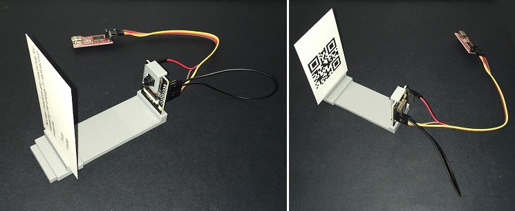
The trivia card is inserted into a holder that can slide towards and away from the stationary camera. The ESP32-CAM is connected to the FTDI programmer. I ran the Video Streaming Server example mentioned in the installation tutorial.
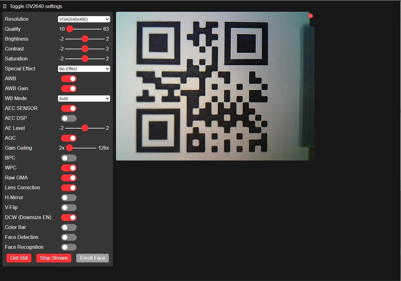
I used this setup to determine the optimal distance between card and camera by sliding the card into a position so that the QR code occupies most (say 90%) of the frame. This turned out to be about 65 mm for me. With the card positioned, focus the camera to get the sharpest image possible buy carefully twisting the lens. To this end I designed a small tool to securely hold the camera in place while the lens was being turned.
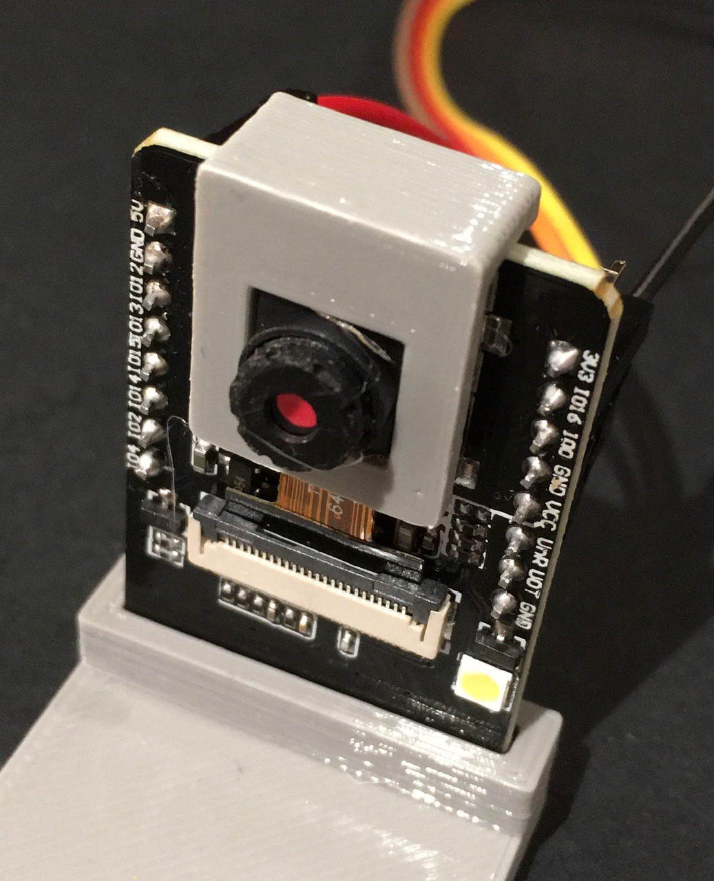
You have to apply a fair amount of torque to adjust the lens.
Once the camera was calibrated it was time to try reading the QR code. It tried a couple of different tutorials, but found that the one linked here worked best for me. The only changes I made to the test code from that tutorial were to translate the Portuguese comments to English, and to enable the ESP32-CAM's on board flash when reading the QR code.
I Think the Answer Is...
For the original Think-a-Tron, I'm assuming that the game play went something like this:
- Someone reads the question from a card.
- Both players verbally declare what they think is the correct answer (A, B, C, T, or F).
- The card is inserted into Think-a-Tron, which is "activated" and reveals the correct answer.
- Players with the correct declared answer manually update their score counters.
- Repeat.
Now I'm assuming this because I have not been able to find a copy of the Instruction sheet that shipped in the box. If anyone out there has this sheet I would be eternally grateful for a copy.
At any rate Think-a-Tron 2020 will work a little differently:
- Someone reads the question from a card.
- Both players lock their answers into Think-a-Tron 2020.
- The card is inserted into Think-a-Tron 2020, which is "activated" and reveals the correct answer.
- Think-a-Tron 2020 automatically increments the score for those players with the correct answer.
- Repeat.
So how would the players "lock their answers" into Think-a-Tron 2020.
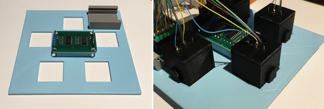
My first though was to use a rotary switch. I actually made one. You can see the details in this log entry. While the rotary switch turned out great, and certainly would have done the job, I'm going to go in a different direction for Think-a-Tron 2020. The key to this new concept is a push button. Not just any push button, but an illuminated push button, and not just any illumination, but WS2812B addressable, smart RGB LED pixel light illumination. It looks like this:
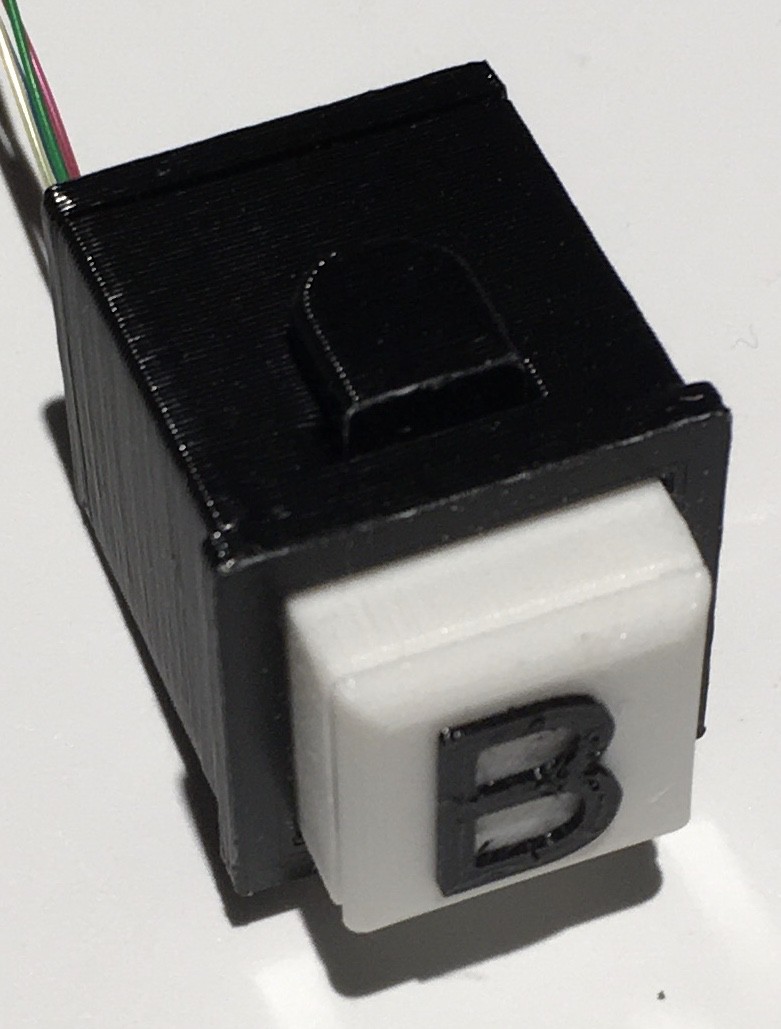
There will be five of these per player, one for each answer choice A, B, C, T, or F. When the player wants to "lock in" their answer, they just have to press the appropriate button, and it will light up. The five will act as radio buttons, so only the last one pressed will ever be the illuminated choice. Since the LEDs can be any color, one can envision changing correct answers to green and incorrect answers to red after Think-a-Tron 2020 has declared the correct choice. There are many blinkenlight possibilities.
To be clear what I have here is a combination of a push button switch and an RGB addressable LED. They are not integrated in the sense that the switch controls the LED in any way, that's all done "centrally".
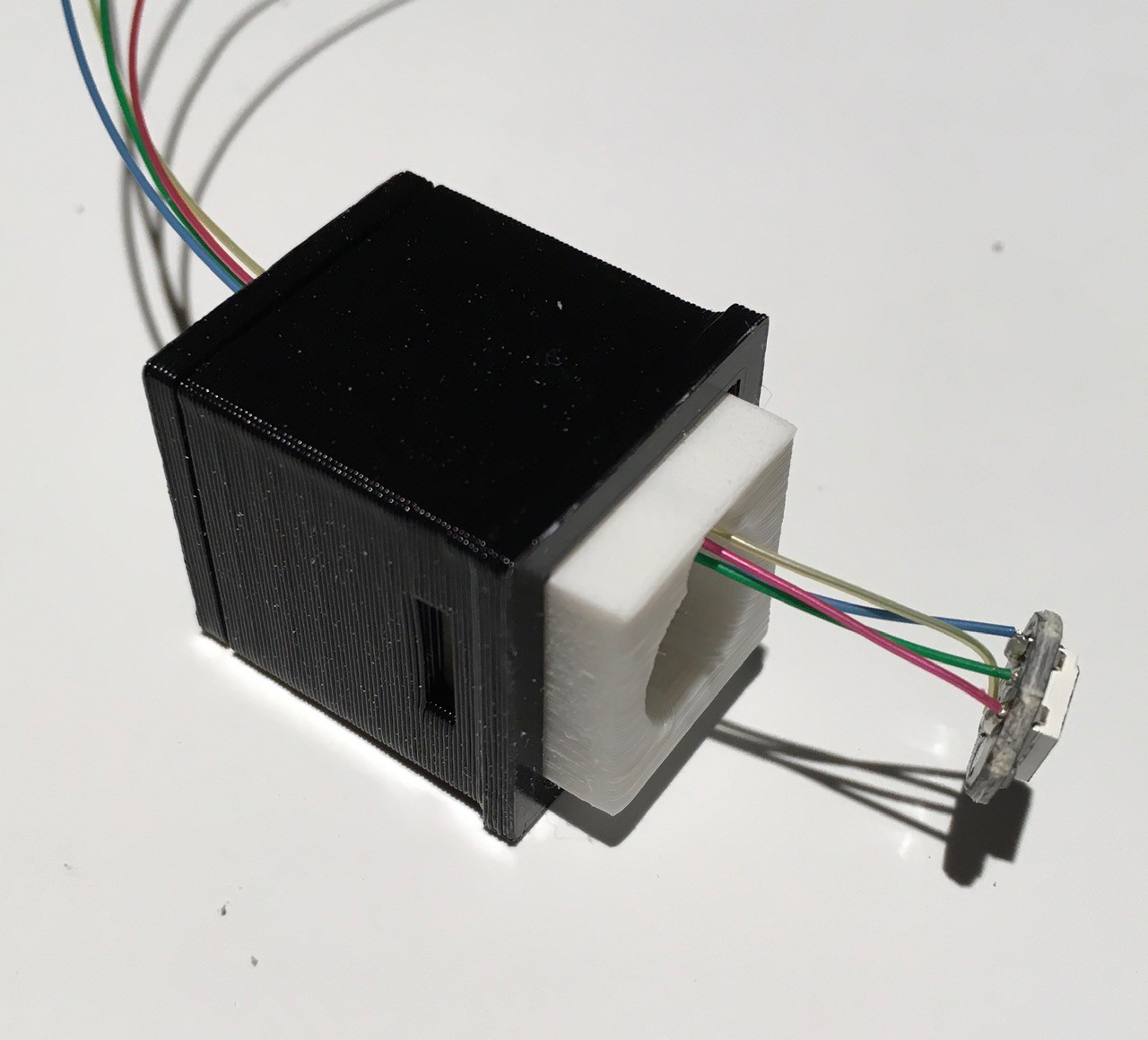
Building a NeoPixel Push Button
I started with a design that I used in my TMD-1 project for the panel buttons, and incorporated the same smart pixel units that I use for the 5x7 LED array. Here are all the parts you need to make one.
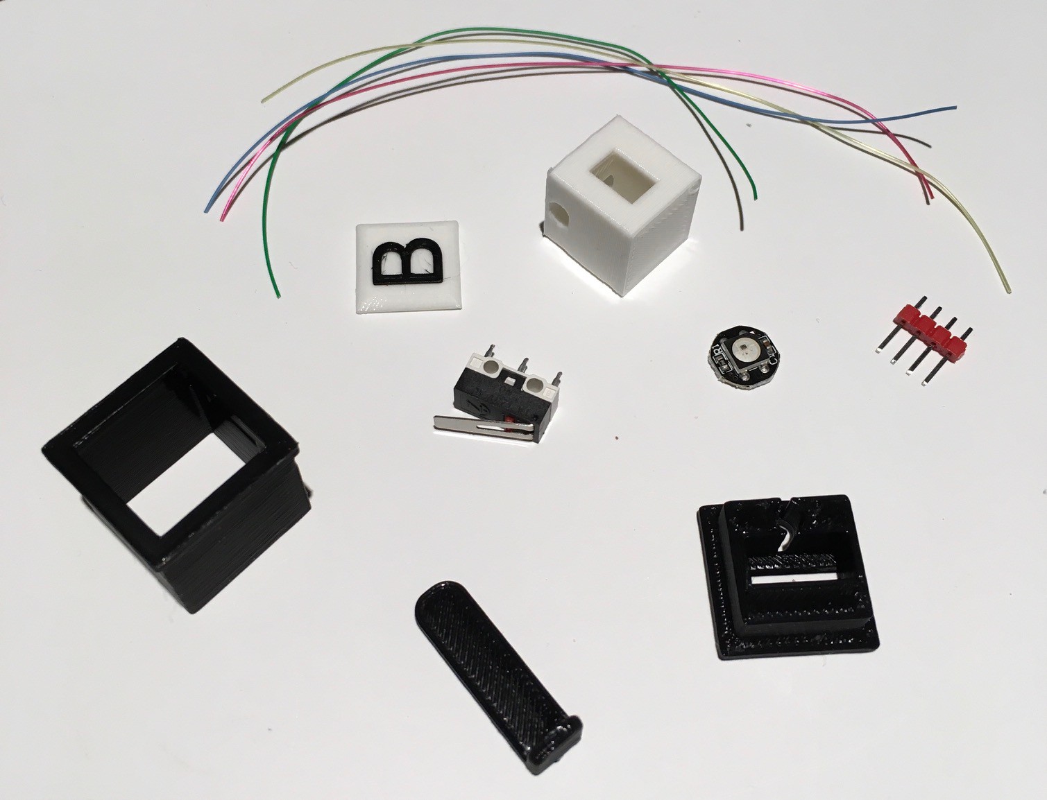
So we are talking about a simple push button switch here that I built around a small micro switch (Amazon: Gikfun Micro Switch Long Hinge Lever (Pack of 20pcs) for Arduino EK1713) that I had lying around.
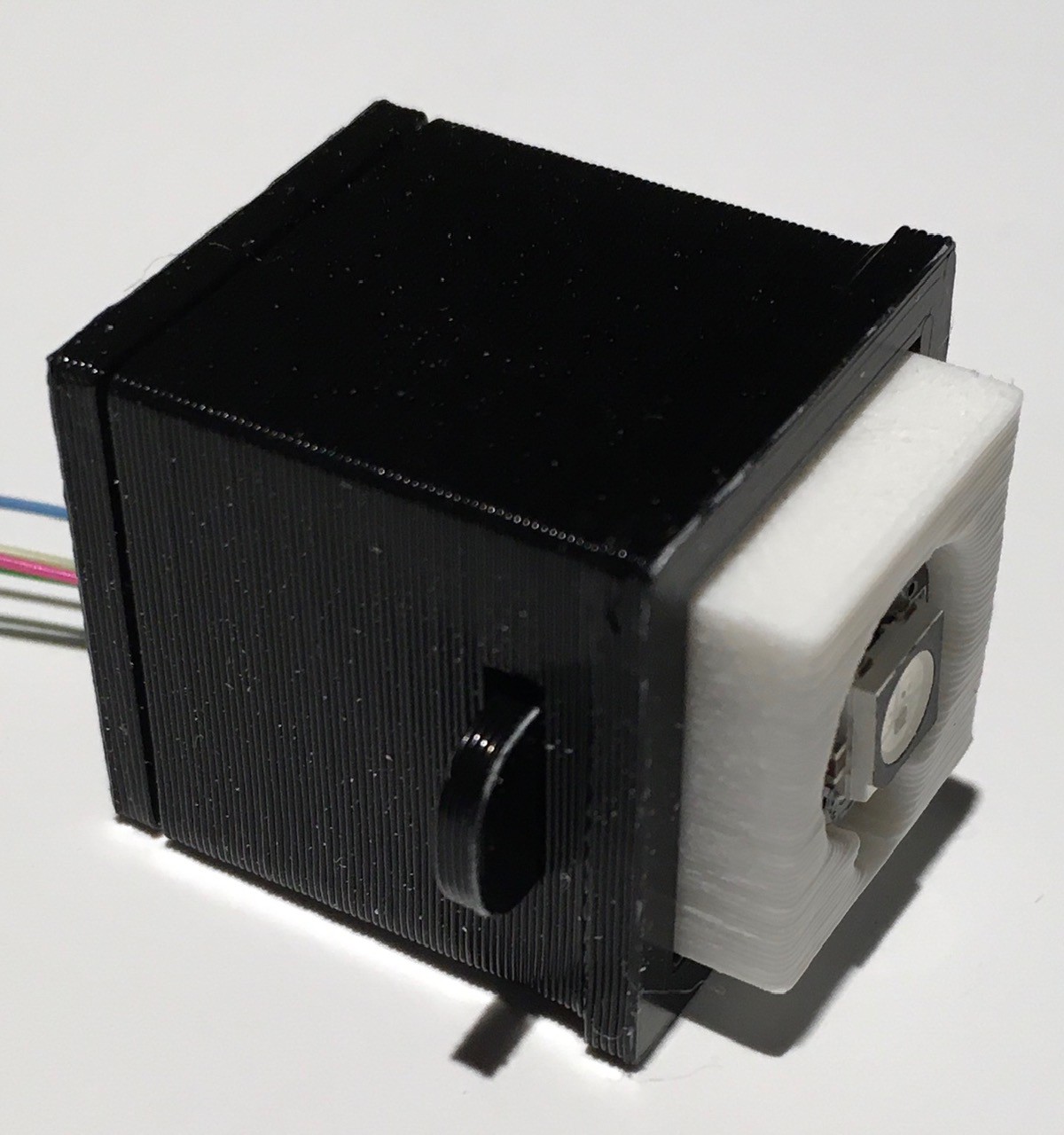
Assembly is pretty straight forward. Start by sliding the micro switch into the base piece making sure that the lever actuator does not extend past the edge of the base (there is one right and one wrong way to do this).
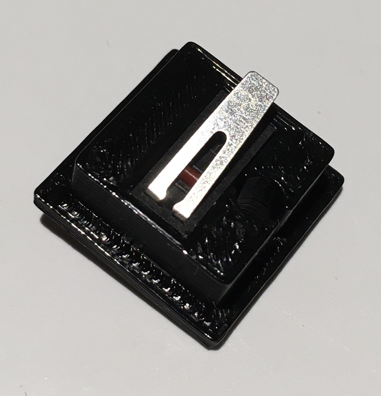
Now attach the base piece to the bottom of the console mounting piece. Mine friction fit pretty good, but you can used a small amount of glue to hold it firmly in place if necessary.
Note the orientation of the hole in the bottom of the base and the slot in the side of the console mounting piece. This is important.
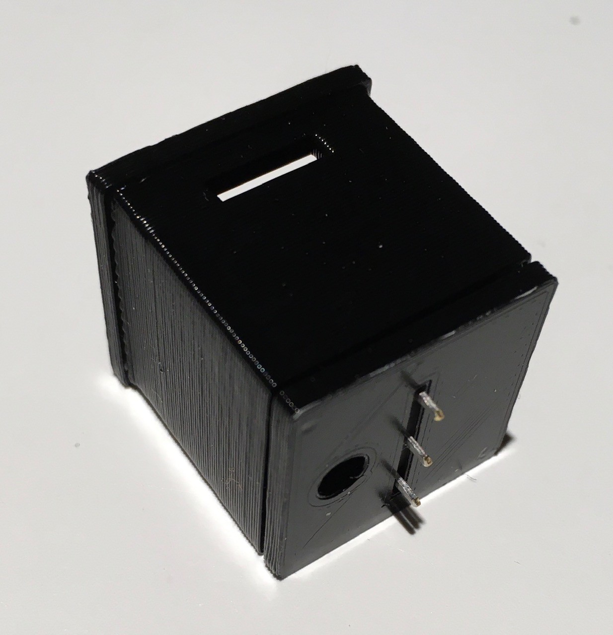
Next slide the button shaft into the console mounting piece. Make sure that the slot on the button is aligned with the smaller slot at the top of the console mounting piece. Also make sure that the hole running down the shaft is aligned with the hole in the base.
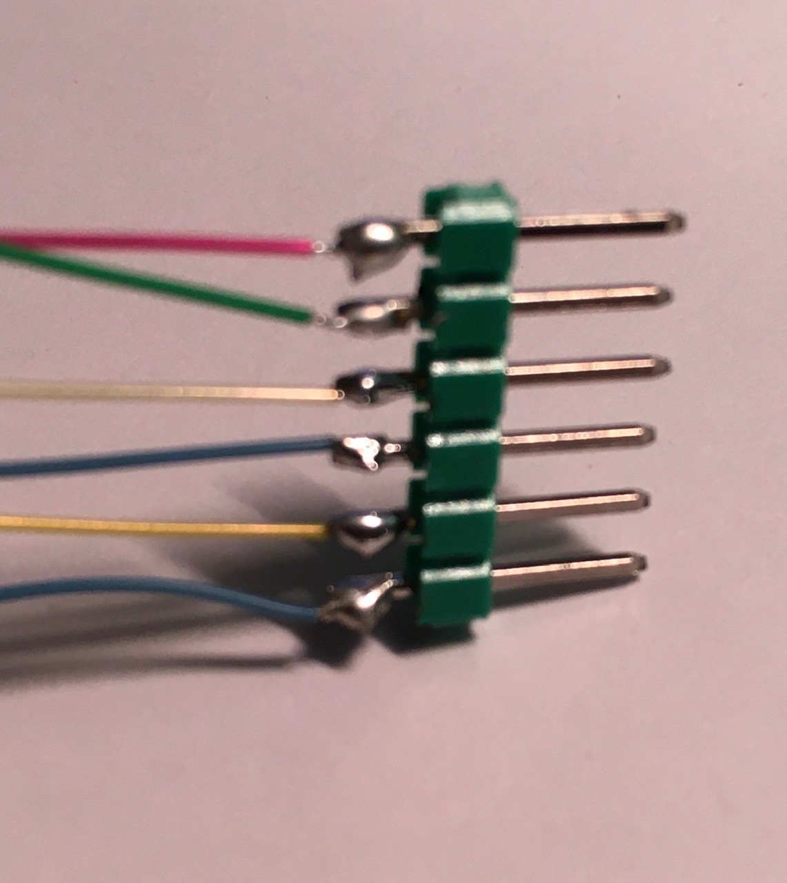
Prepare the single NeoPixel unit by attaching short wires to the +5V, GND, Data In, and Data Out pads. I used 30 AWG wire for this.
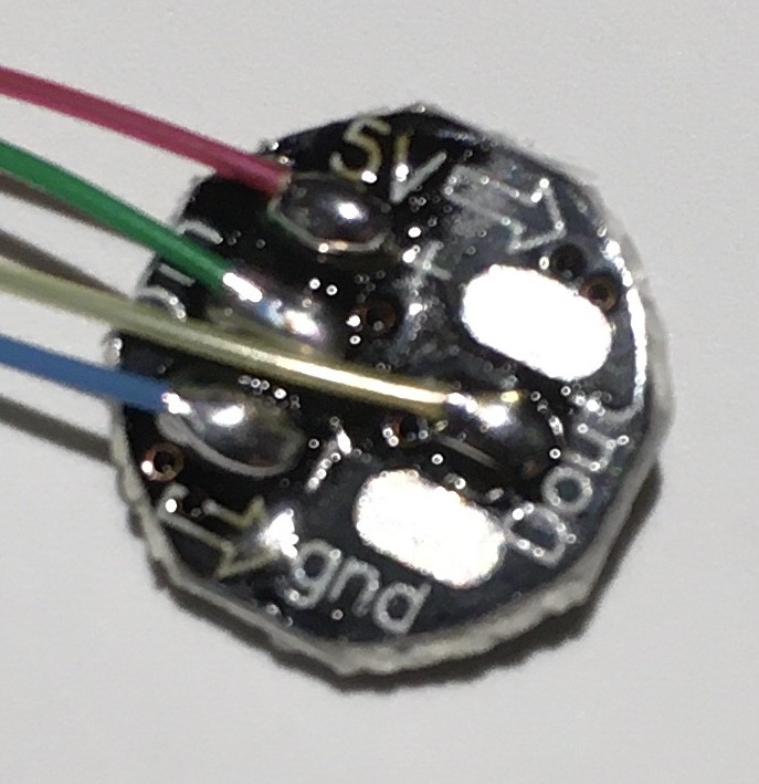
Carefully bend the wires so that they are both perpendicular to the PCB and off to one side. Then slide the wires all the way down the shaft and out through the base of the button.
Push the wires and PCB all the way back until the PCB is inserted into the circular recess in the button shaft.
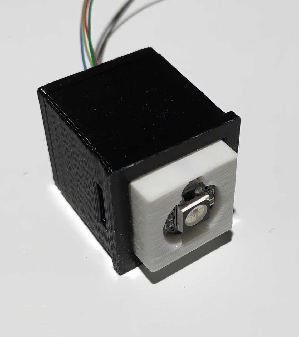
Slide the locking tab into the slot at the top to hold the shaft in place. This tab will also be used when it is time to panel mount the button.
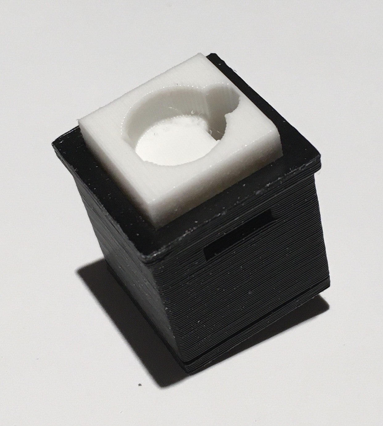
I attached the LED's wires to a header for ease of use with this small gage wire.
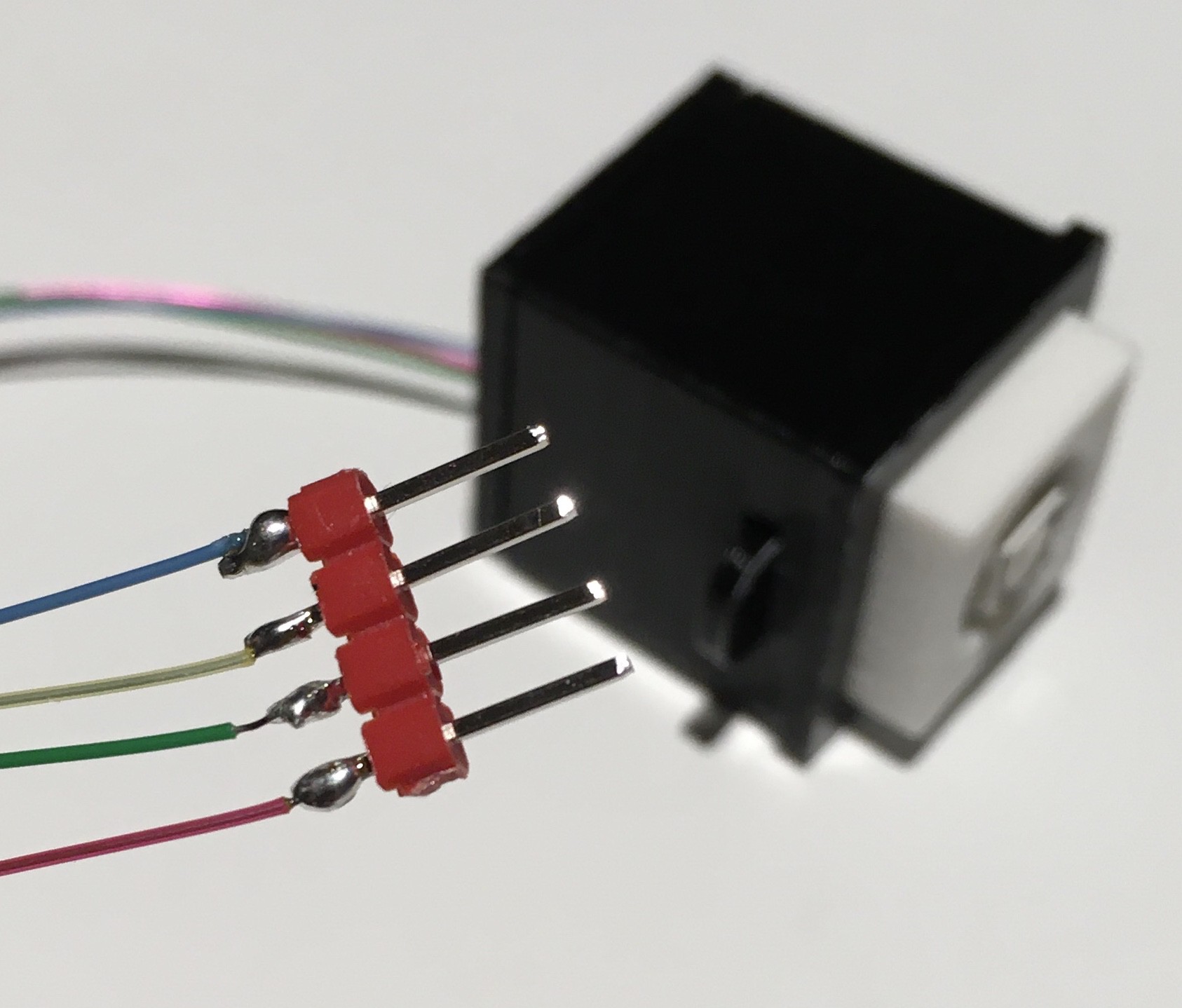
At this point since everything is still accessible, I would test the push button. When it has checked out you can glue the letter piece to the top of the shaft.

One down ten to go.
Ready Player One
With all of the little bits sorted, I just finished the first major subassembly for Think-a-Tron 2020, the Player Console.
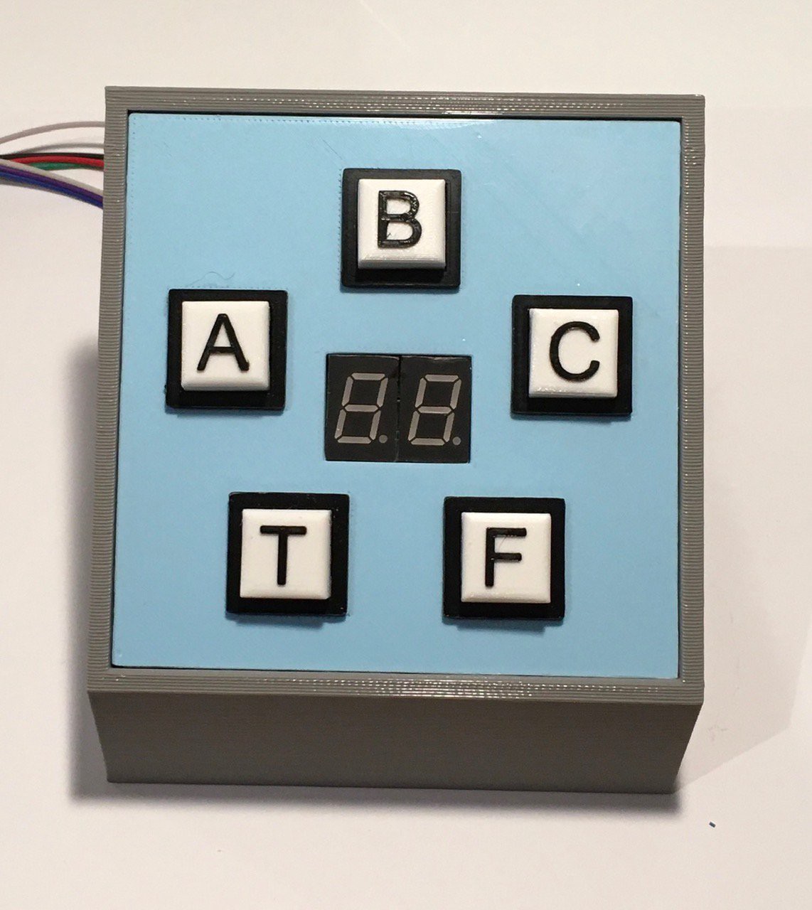
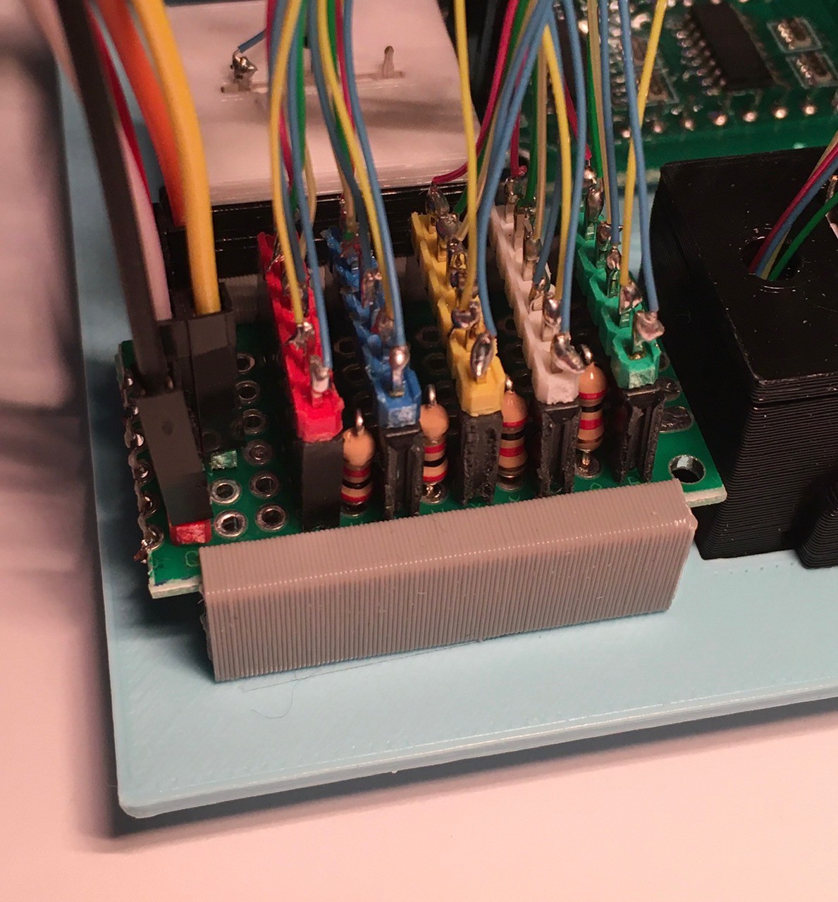
You'll notice something new in the picture above. A two digit seven-segment display that will be used to keep track of the player's score. I made five of the NeoPixel push button switches I talked about in my last log entry. The only change I made was to incorporate the switch leads into my header jack.
So from top to bottom we have:
- +5V
- Led In
- Led Out
- GND
- Switch Common
- Switch NO
I used a perf board with headers to help sort out the wiring. This Player Module also has the four 2K resistors used to determine which button is pressed. Point-to-point wiring was tight but doable. If I could get PCBs cheaply (it's the shipping to Canada that kills me), I would have gone that route.
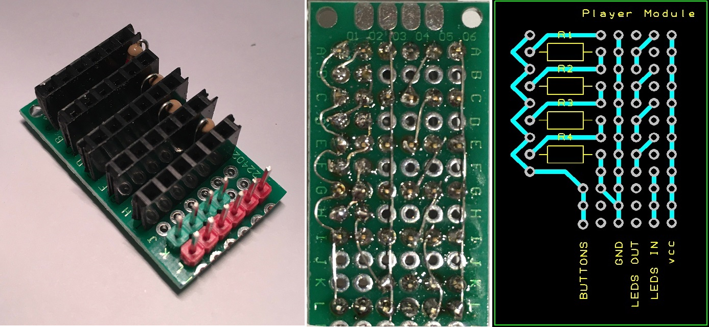
I created a small slotted clamp to hold the Player Module perf board and attached it with two sided tape (or glue) to the back of a panel that I printed to mount the switches and display.
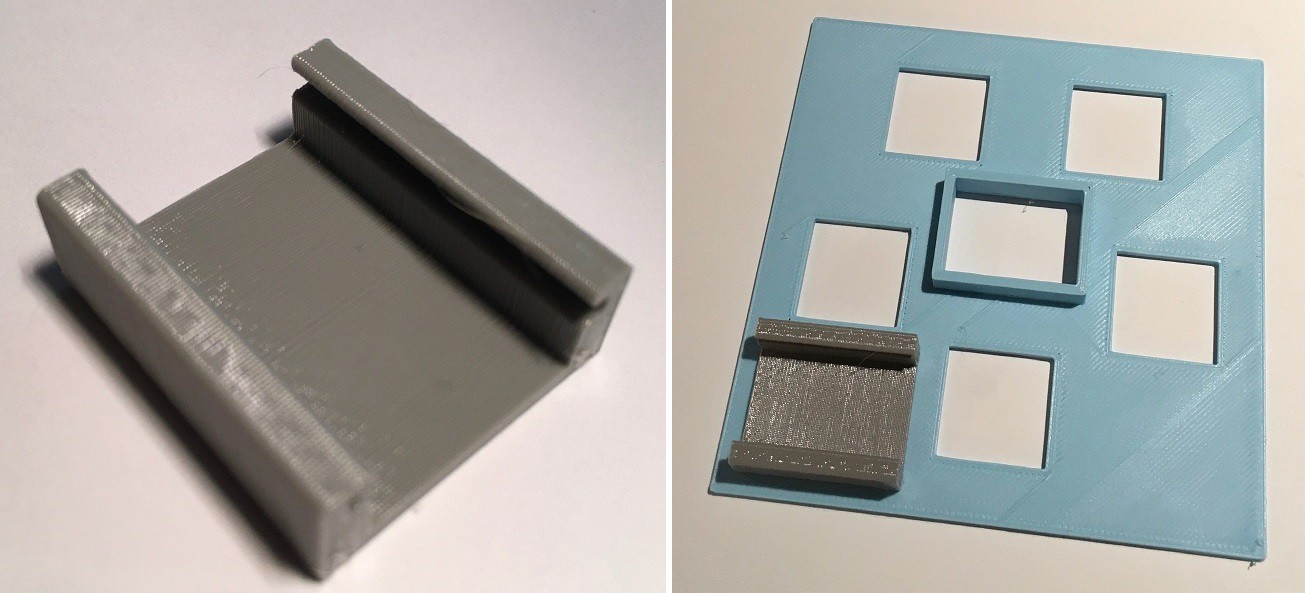
I added headers to the back of the seven-segment display (a Robojax Whmxe 595-2 74HC595 Driving 2 Digit 0.5in Seven Segment Display for Arduino - from Amazon) and mounted the display in the center rectangle with the raised edges. The front of the display should end up being flush with the front face of the panel. The switches are pushed in from the front of the panel and held in place with the tabs you can see in the second picture below.
I slid the perf board into the holder and began plugging in the switches.
With everything attached mount the Player Panel onto the printed console seen below.
Core Console
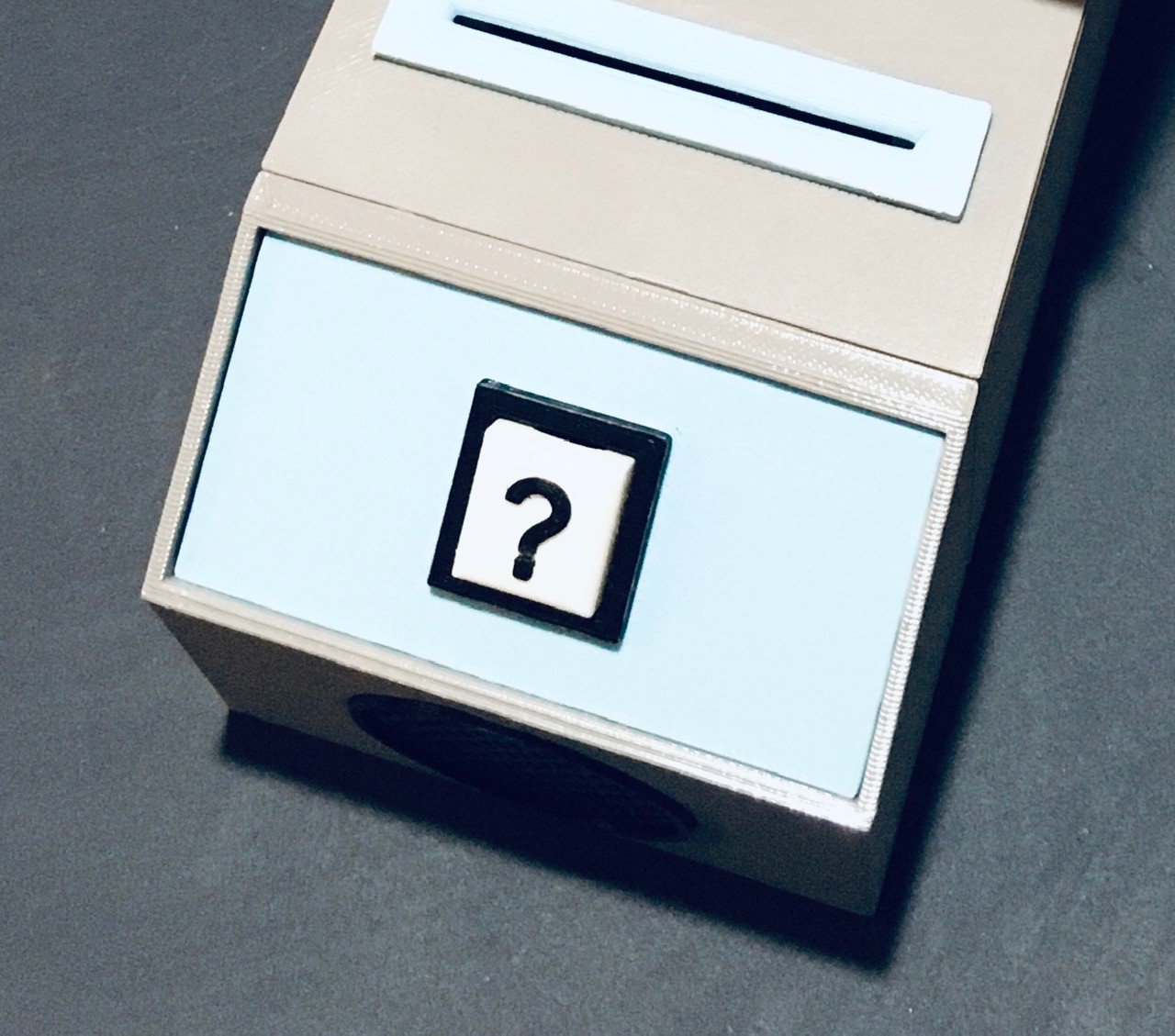
The heart of Think-a-Tron 2020 consists of three main parts: the camera QR code reader section, the display, and the question (?) console with speaker.
The ESP32-CAM is mounted in a rectangular box forming the main part of the core section.
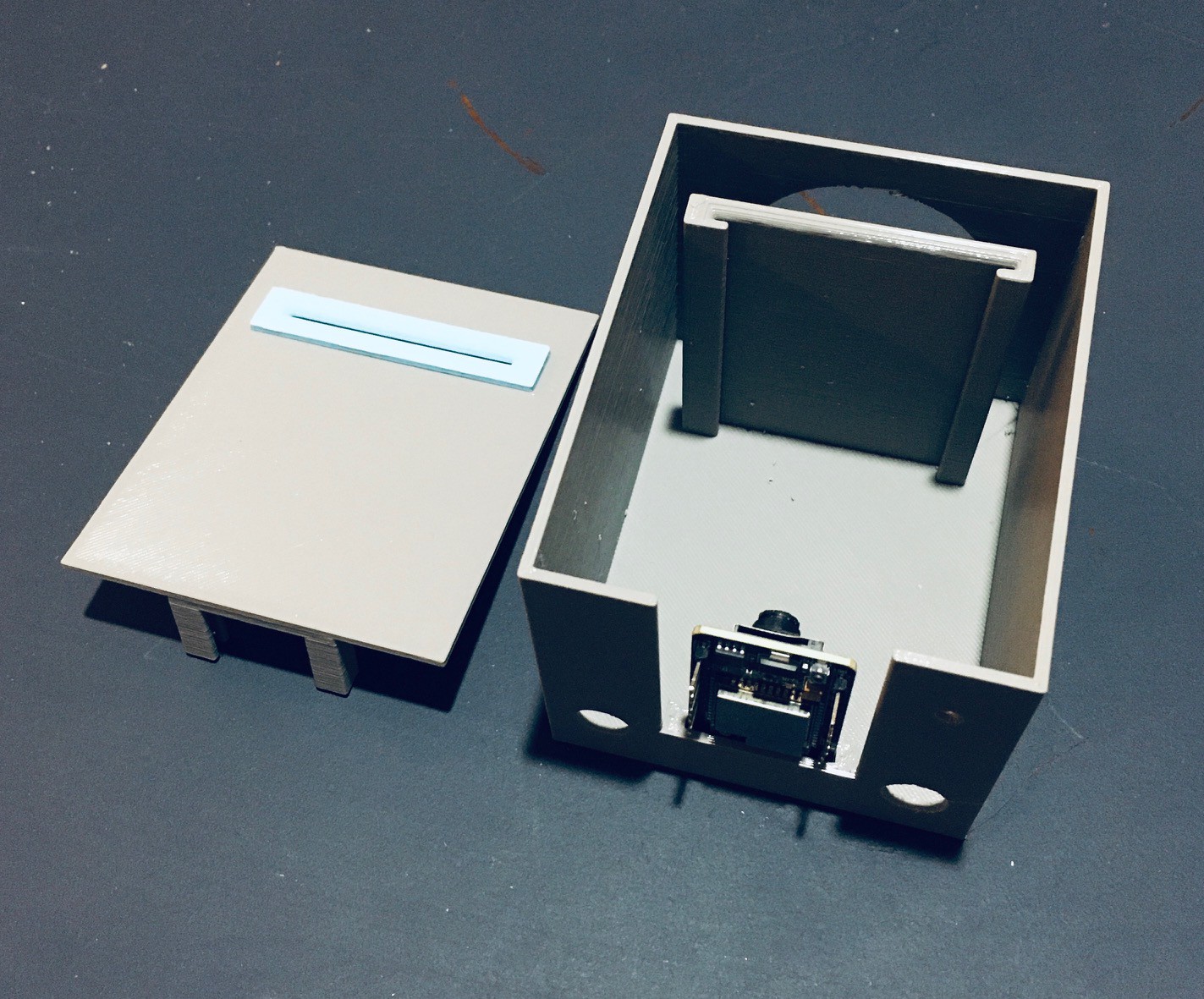
You can see there is a mounting slot for the ESP32-CAM and a guide to hold the question card (with QR code) at the correct distance for the camera to be able to read it. The top for this section has a slot that lines up with the guide to accept the card.
I had some buck converters lying around so I used one to power the project.
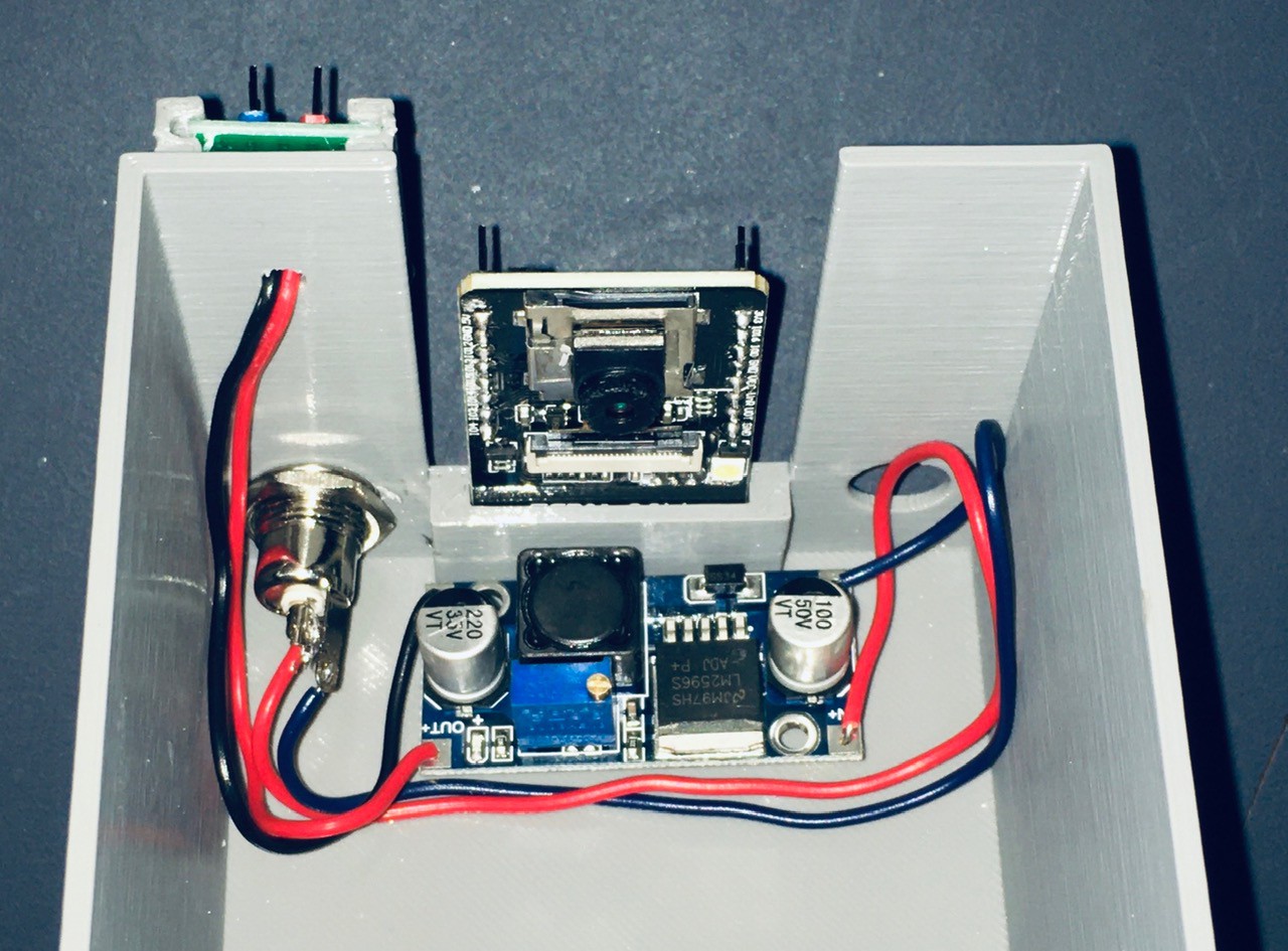
The power jack supplies the input voltage to the converter, with the output of 5V and GND connected to a small power rail that I made with headers and perf board. I mounted this with a small 3D printed bracket that I glued to the back.
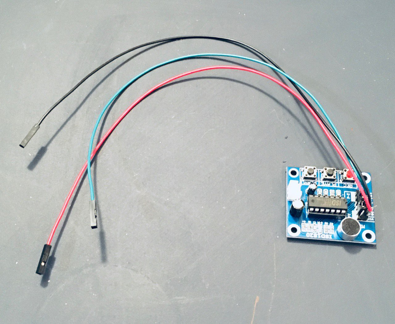
I decided that I want to add a sound effect to the project so I purchased a cheap solid state recording and playback module (ISD1820 Sound Voice Recording Playback Module with Mic Sound Audio Microphone - Amazon).
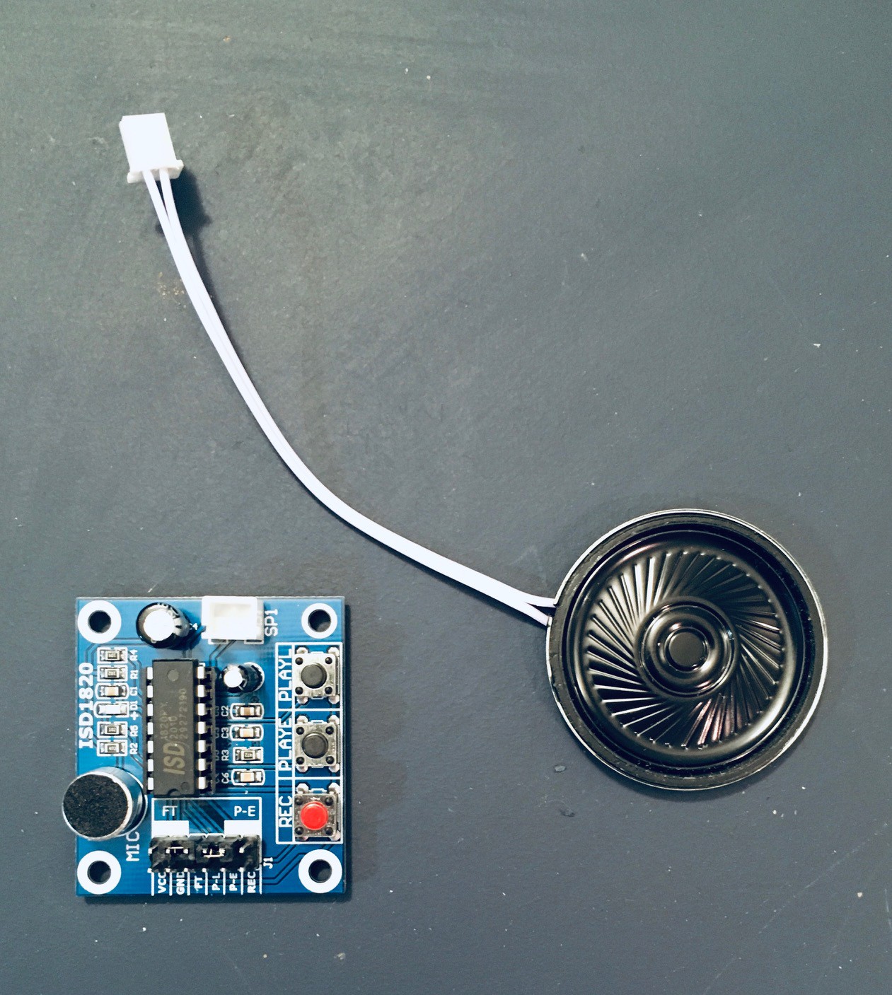
I attached some jumper wires to the VCC, GND, and P-L connectors. Whatever you record on the device (which can hold about 10 seconds of sound) will play back so long as the P-L pin is held high).
There is a slot for the sound module on the opposite side of the card holder.
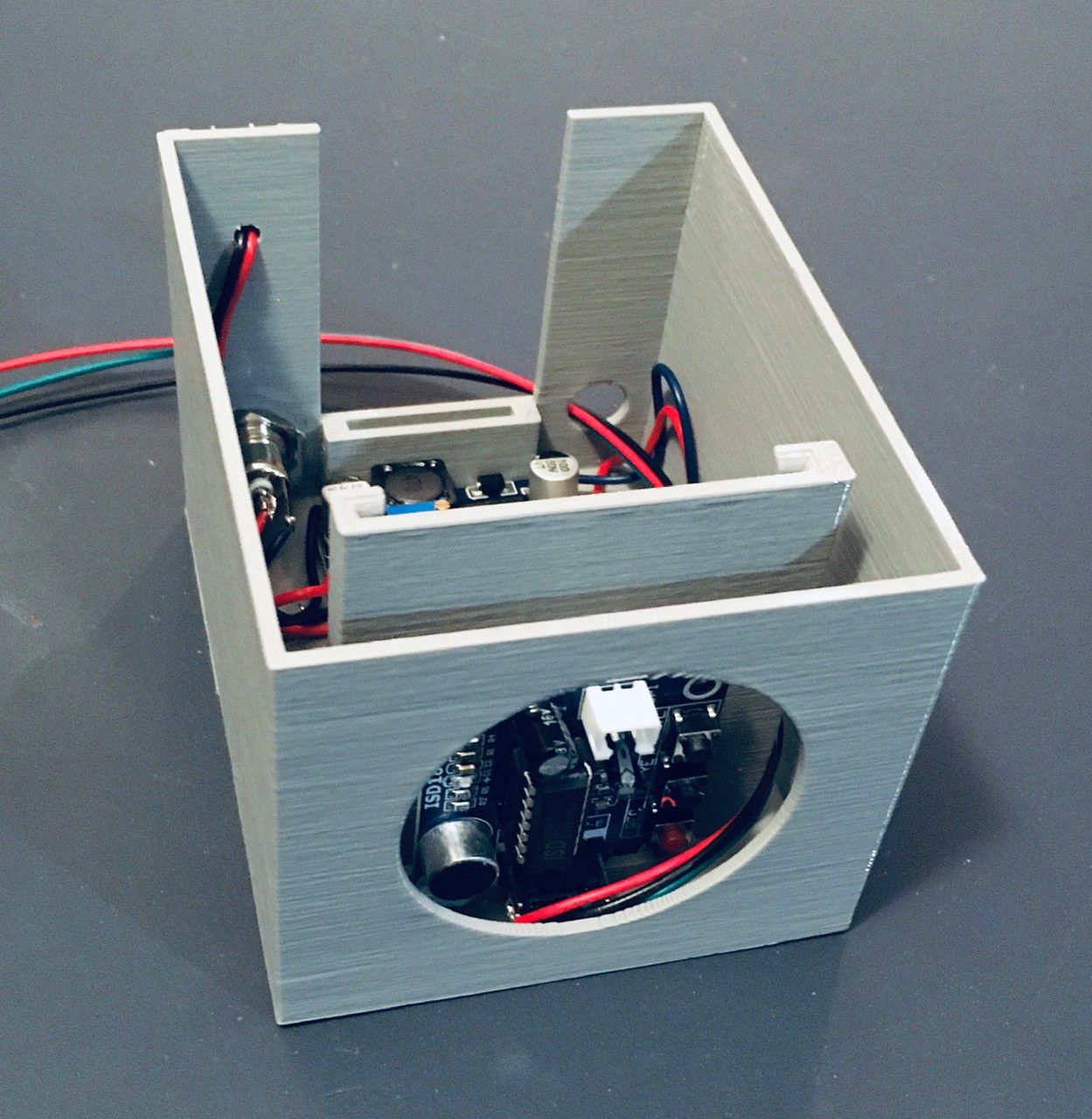
Run the jumpers along the left had side and out through the hole at the back as can be seen above. I secured the module with a piece of two sided tape.
I printed a small console to hold a single button and the speaker for the sound module.
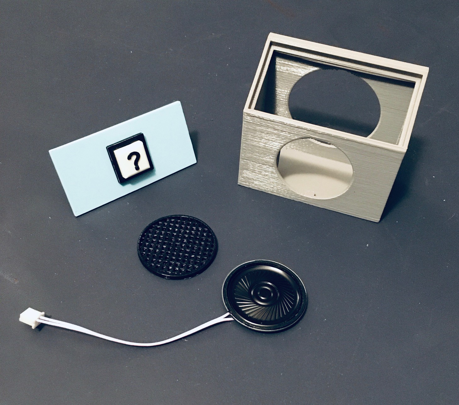
I attached the printed speaker grill to the console front with a few dabs of glue. There are slots to mount the speaker, which I secured in place with some electrical tape. I attached leads to the push button common and NO pins.
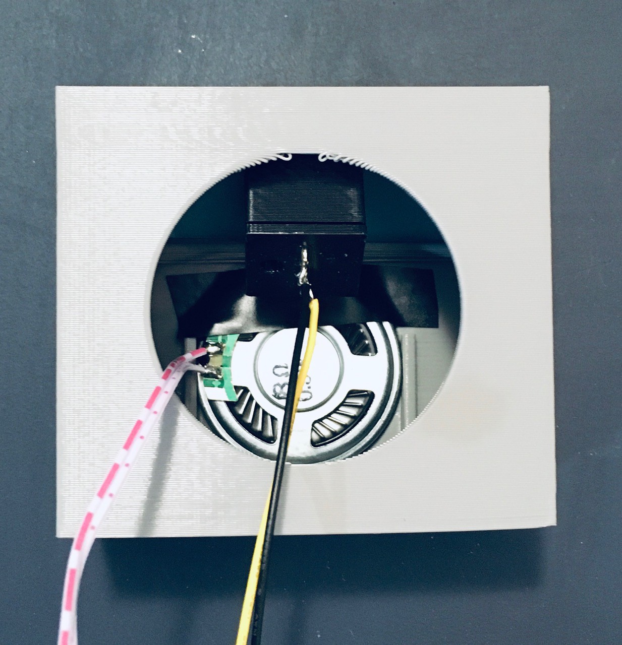
Attach the speaker to the sound module and run the push button cables along the side and out the back the same as was done with the sound module. Attach the button panel to the console. Glue the console to the main part of the core section.
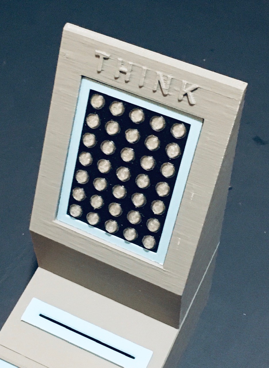
I printed a stand to hold the 5x7 NeoPixel display. I modified the wiring for the display case slightly so that the wires exited straight back instead of down.
Insert the display with case into the stand and glue the assembly to the top of main core section.
I'm coming down to the wire. I just have to incorporate the player one and two panels and the hardware and software will be done.
A Sneak Peek
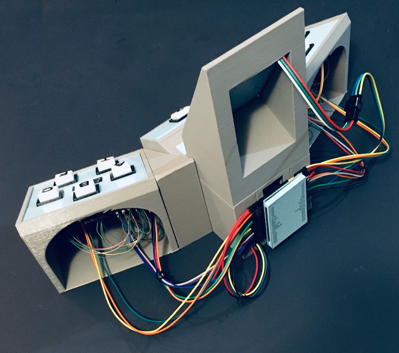
While I was assembling the various pieces of Think-a-Tron 2020 it occurred to me that a wrap-around console look might be cool. This is what I ended up with.
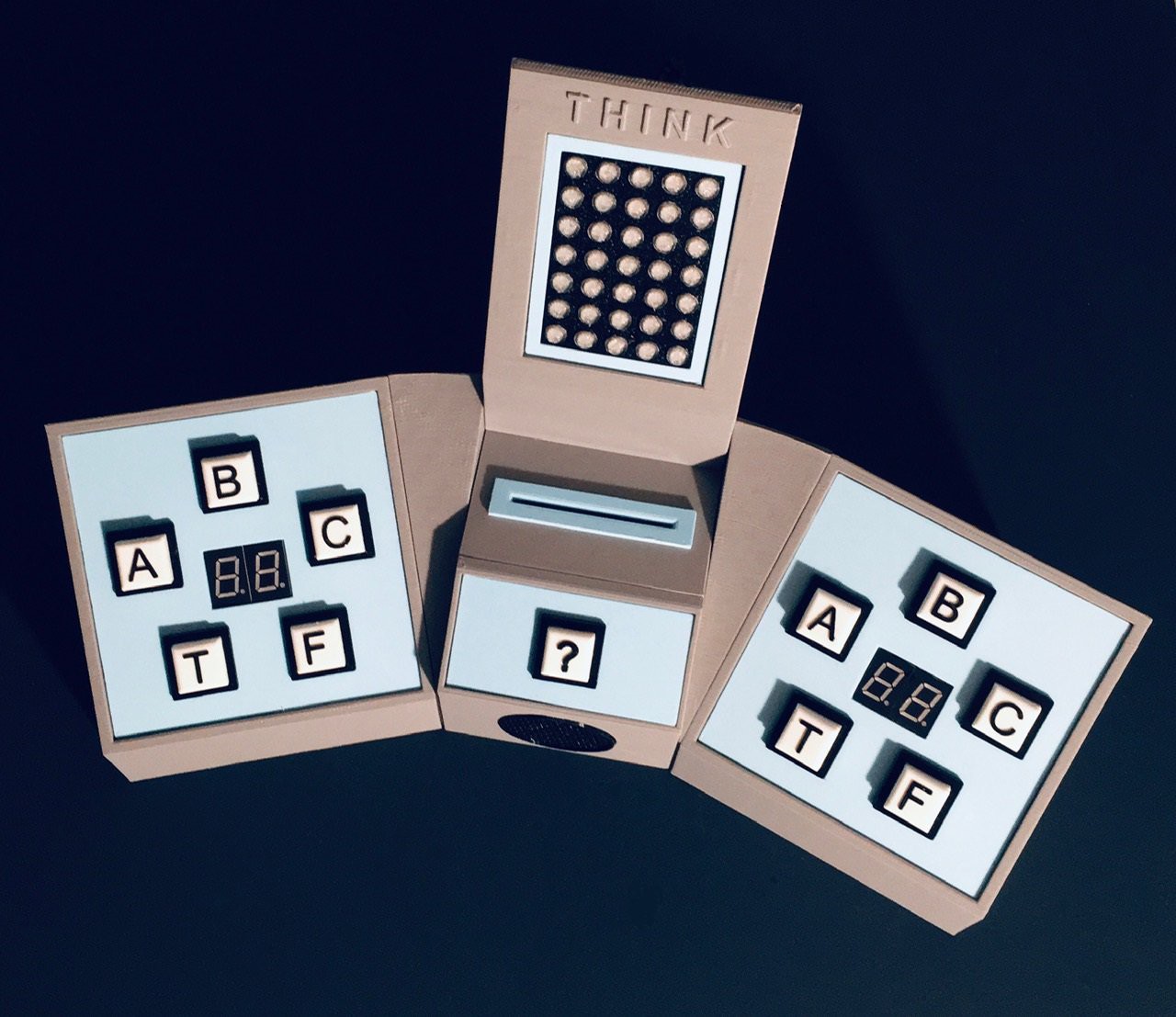
I glued the Core and Player consoles together with some 3D printed wedges.
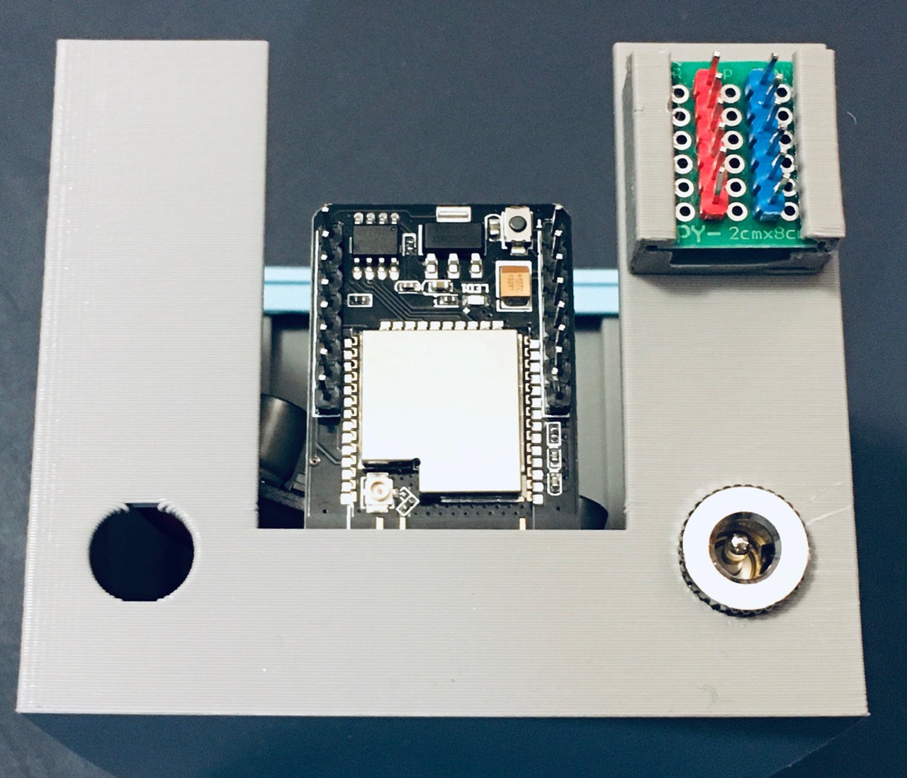
Wire Wrangling
So with everything together I realized that I had to deal with a lot of wires.
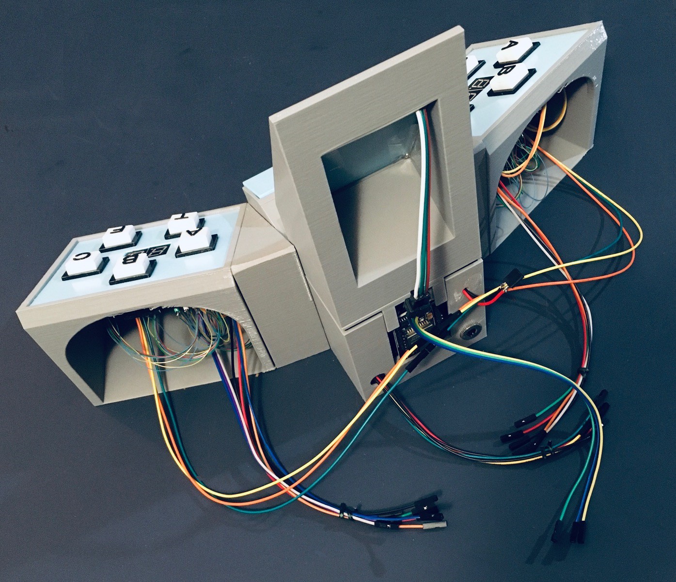
If I were doing this again I would definitely put more thought into the whole wiring thing. But moving forward I need to try to to tame this mess. I decided to create a "shield" for the ESP32-CAM that would at least position the correct headers on the side that the wires were coming from. I removed the small power rail that I had made to make room for the new shield.
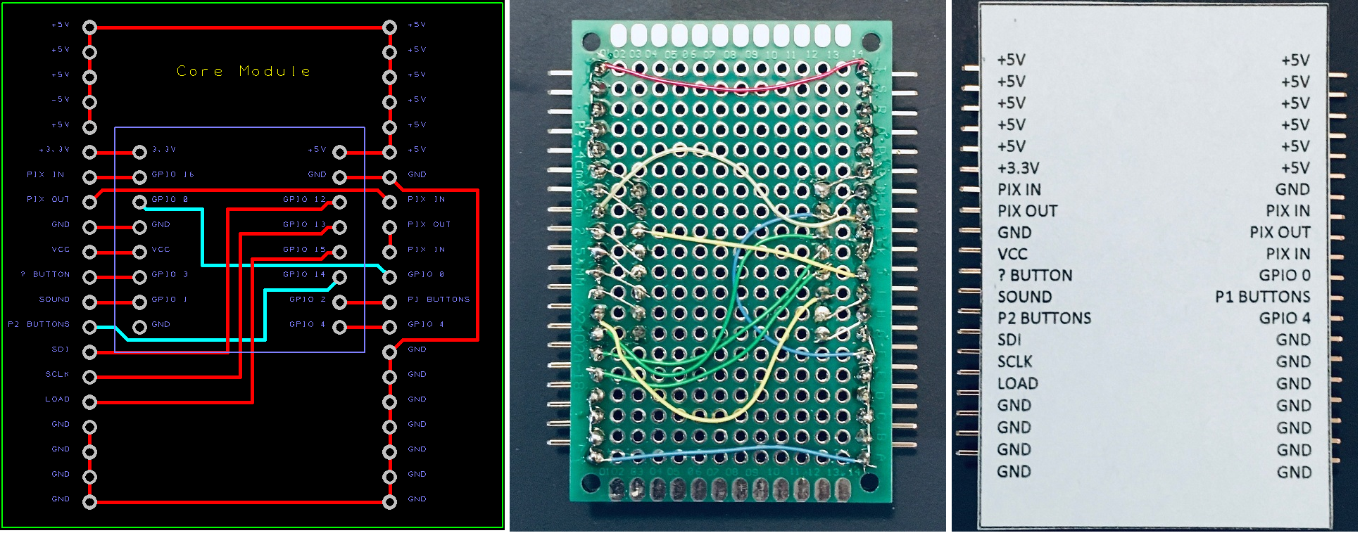
Again if I could afford the shipping I would have made a PCB. As it is I'm getting lots of practice doing point-to-point wiring on proto boards for this project. I printed a card with the expected connections (which I assure you do line up with the pins when you don't have photo perspective issues). Here is the result.
A little better I think. I don't mind the showing what happens behind the curtains. So that's pretty much it for the hardware. Now to marry all of my little test sketches into a proper program for Think-a-Tron 2020.
For Want of a Pin...
I'm coming down to the wire, literally, for my Think-a-Tron 2020 project. The anticipation is killing me but I have a couple of small problems. For one I'm a pin short. I thought I was OK based on the documentation I had on hand. This was my plan.
| ESP32-CAM PIN | Think-a-Tron 2020 Connection |
| GPIO 0 | Not Available Camera XCLK |
| GPIO 1 | Trigger Sound Effect |
| GPIO 2 | Player 1 Answer Buttons (ADC) |
| GPIO 3 | NeoPixels (all 45 of them) |
| GPIO 4 | Camera LED |
| GPIO 12 | Score Counters SDI |
| GPIO 13 | Score Counters SCLK |
| GPIO 14 | Player 2 Answer Buttons (ADC) |
| GPIO 15 | Score Counters LOAD |
| GPIO 16 | ? Button *** |
The problem is that GPIO 16 is in fact used by the Camera although this is not documented anywhere I could find. Any use of GPIO 16 causes the camera to crash when capturing an image (sigh).
The other issue is that the analog readings that I am getting from the player inputs suck. Even averaging multiple analog reads sometimes results in the wrong button being "selected".
So I have ordered a 16 bit high precision 4 channel I2C IIC Analog-to-Digital Converter based on the ADS1115 PGA ADC converter chip (Amazon).
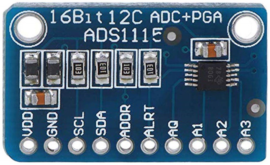
So in a couple of days I'll see if I can convert two pins for an I2C bus into 3 inputs: Player1, Player2, and ? buttons. Hopefully I can kill two problems with one piece of silicon.
It Worked!
The ADS1115 did the trick. Not only did it get around my "one pin short" issue, the analog reads are now rock solid too.
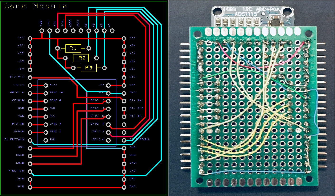
I redid the "shield" incorporating the ADS1115 and everything works really well now. I consider the hardware to be officially complete at this point. I'm still tweaking the software a bit but that's pretty close too.
I have also started to write a Python script that will make the creation of trivia question cards, well, trivial. I see the light at the end of the tunnel.
Trivially Making Question Cards
I'm relatively new to Python, but I'm beginning to appreciate how quickly you can get things done with it. What I thought might take a few days turned out to be more like a few hours.
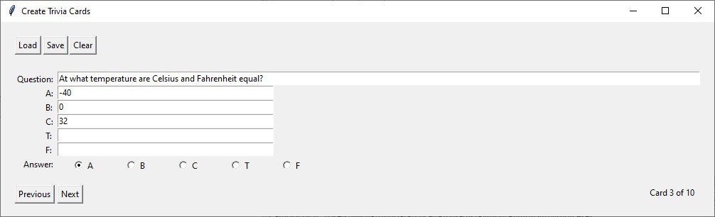
So the application works with one sheet of Avery 5371 business cards at a time. You simply key in ten questions, choices, and answers then press the Save button.
- A text file with your data so that you can Load it back in to make changes.
['Humans and chimpanzees share roughly how much DNA?', 'Roughly how long does it take for the sun’s light to reach Earth ?', 'At what temperature are Celsius and Fahrenheit equal?', 'What modern-day country was Marie Curie born in?', 'How many hearts do octopuses have?', 'Apollo 15 was the first moon mission to carry a lunar rover?', 'On the periodic table, what symbol stands for silver?', 'Mercury is the only planet in the solar system without a moon.', 'What was the name of the first man-made satellite launched by the Soviet Union in 1957?', 'What is the biggest planet in our solar system?']
['10%', '8 minutes', '-40', 'Hungary', 'One', '', 'Si', '', 'Sputnik 1', 'Uranus']
['52%', '8 hours', '0', 'Poland', 'Two', '', 'Ag', '', 'Echo 1', 'Jupiter']
['98%', '8 days', '32', 'Czechoslovakia', 'Three', '', 'Na', '', 'Explorer 1', 'Neptune']
['', '', '', '', '', '', '', '', '', '']
['', '', '', '', '', '', '', '', '', '']
[3, 1, 1, 2, 3, 4, 2, 5, 1, 2]
- A PDF of the questions and choices nicely formatted one per card.
- A PDF of the ten QR codes laid out to align with the correct questions when two sided printing.
It would be pretty easy to setup a trivia night with this program.
I did run into one issue creating this program. I'm using the ReportLab PDF Library to layout the cards (which works great by the way). My intention was to use the corresponding reportlab-qrcode library to generate the QR codes on the fly. I had thoughts or obfuscating the "payload" of each QR Code since if you look very closely at the QR Codes for simple "A", "B", "C", "T", and "F" payloads you can in fact distinguish between them.
Unfortunately the QR Code library I'm using on the ESP32 side would not read the generated codes. I tried many different variations but, in the end, decided to employ the QR Code images that I have been using all along. These images were created online at QR Code Generator.
Wrapping Up
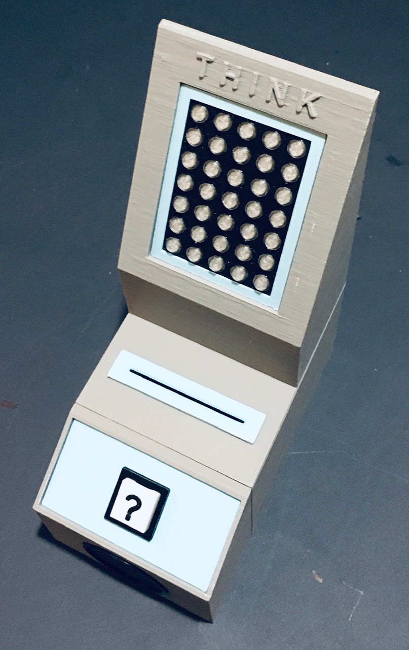
The hardware and software are finished and there is now an easy way to create trivia cards. Here is a video of Think-a-Tron 2020 in action.
Users read the trivia question from a card and "lock-in" their answers via the labeled push buttons. The card is then placed into the slot and the ? button pressed to tell Think-a-Tron to determine the correct answer. After a little thinking time (revealing the "man in the machine") the correct answer choice is displayed on the 5x7 pixel display and the players scores are updated. The answer selection buttons will turn green for a correct choice and red for a wrong pick. Pressing the ? again will reset Think-a-Tron for the next question. Pressing and holding the ? button for more than 5 seconds will reset the scores to 0.
When I look back at my goals for this project I think that I have accomplished at least two of the three.
- I want to build something that is clearly a Think-a-Tron derivative. I'll let you be the judge, but I THINK there is a pretty good resemblance.
![]()
- I would like to maintain the 60's mainframe vibe of the original. I don't think I nailed this one. Think-a-Tron 2020 doesn't scream 60's computer to me. Mind you I'm not unhappy with the look. I get a more 60's alien sci-fi computer vibe. I'm OK with this.
- Have some fun along the way. You'll have to take my word for this one, but putting Think-a-Tron 2020 together was a blast.
Bonus Project - Think-a-Tron Mini
My Inspiration
When I was designing Think-a-Tron 2020, my plan A was to use an ESP32-CAM to read QR codes off the back of some business cards. I did have a backup plan though. I ordered a GM67 Bar Code Reader Module from AliExpress just in case.
Well the ESP32-CAM worked out great. The GM67 arrived around the time I was wrapping up Think-a-Tron 2020. Still I thought I should check it out.
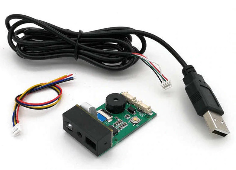
This is what shipped in the box. It's a solid unit. The USB cable and wired connector for the UART port were nice bonuses.
When you plug the GM67 into a PC via the provided USB cable it attaches as a keyboard. Open any text editor and point the device at a bar or QR code and the payload strings appear in the editor. A very cool out of the box experience.
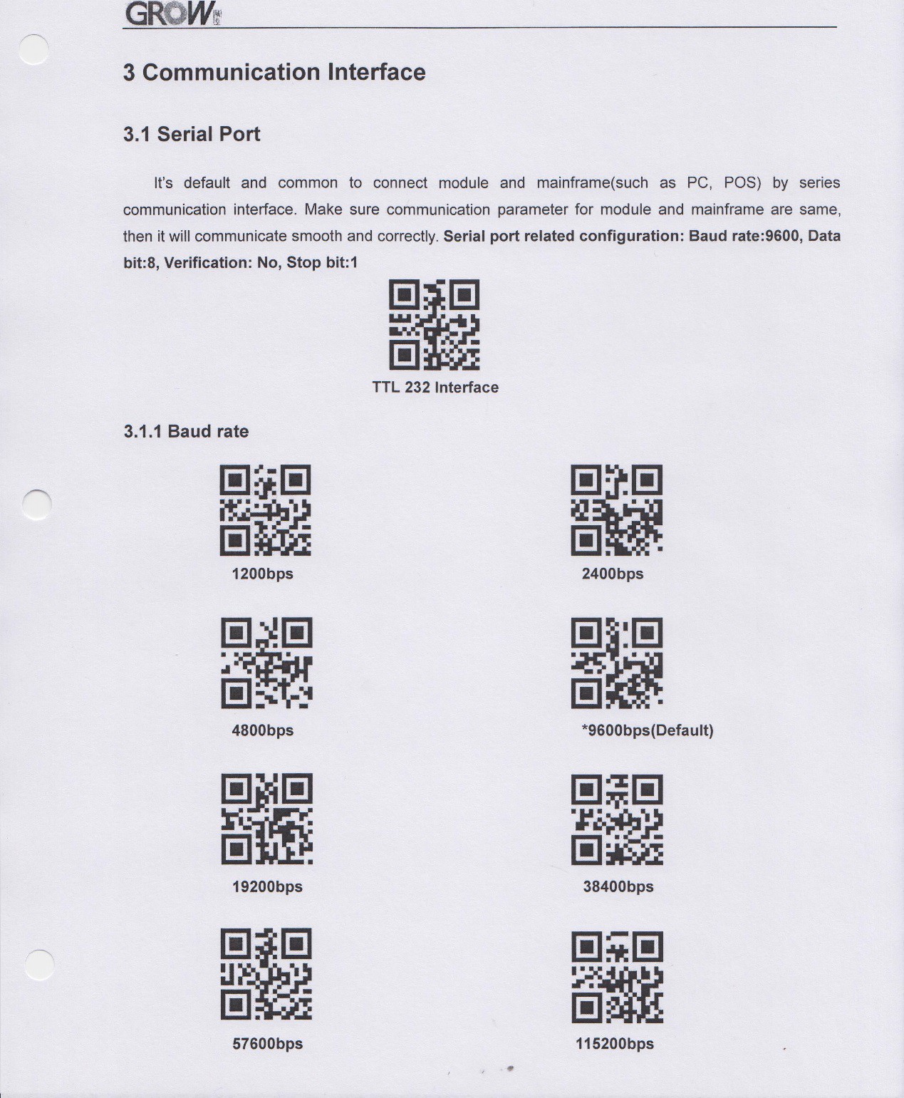
So I cracked open the manual and this is where I got my mind blown a bit. The first few pages were the expected technical specifications and interface definitions. But when I got to the configuration section all I saw were pages and pages of QR codes. The very first QR code was to reset the unit to factory defaults. There were QR codes to configure the serial port (baud, parity, stop bits, etc.) , codes to change the default behavior of the unit (manual, button trigger, continuous, etc.), codes to change the keyboard interface by country, and many more. Virtually all the configuration was done by having the unit scan a QR code. This may be old hat to some of you out there, but this was definitely new to me. Here is a sample page.
So this whole notion of using QR codes to alter the running state of the reader, got me wondering how else you might take advantage of this capability. Since I had just finished Think-a-Tron 2020 my thoughts drifted in that direction and Think-a-Tron Mini was born.
The Design
While the end result did turn out to be pretty small in size, when I first started considering the Mini name, I was also thinking about Minimal. What would a Minimal Viable Product implementation of a Think-a-Tron look like. How could I pare down Think-a-Tron 2020’s eleven buttons, two seven segment displays, and 5x7 LED display. Well if all of the buttons were replaced by cards with QR codes, and the seven segment and 5x7 LED displays were combined into a small LCD display, that would do the trick.
Also since this was a "spur-of-the-moment" kind of project I was hoping to do something with parts that I already had on hand.
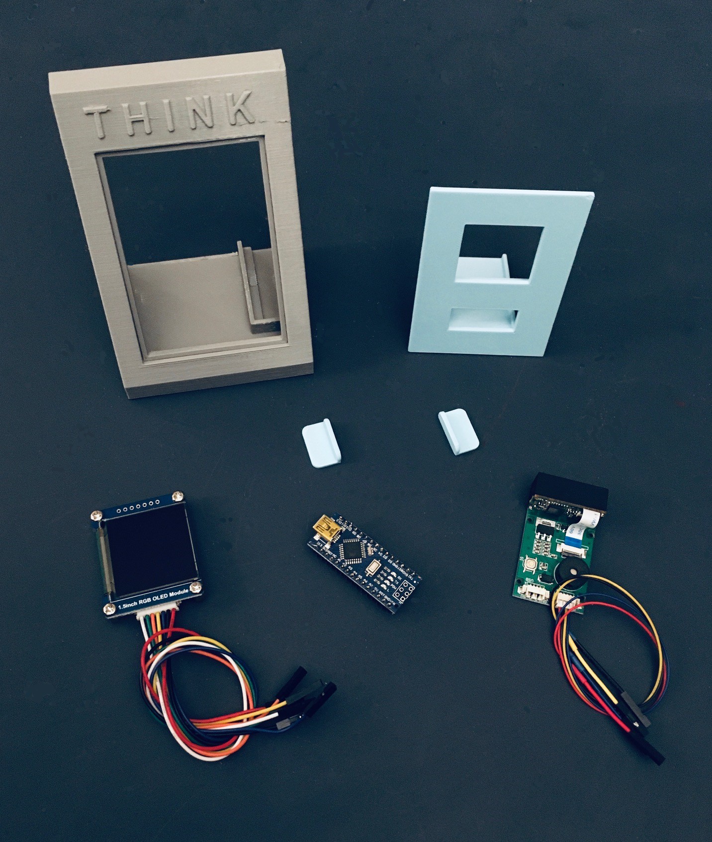
Fortunately I had a Waveshare 1.5 Inch RGB OLED Module and an Arduino Nano in my parts box, and it turns out that's all I needed. Because I had all of the parts on hand I was able to pull this project together in just three days.
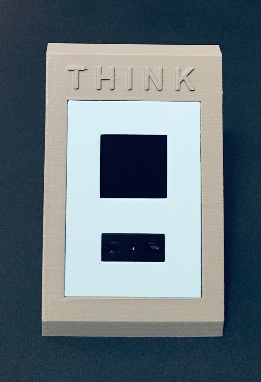
The Build
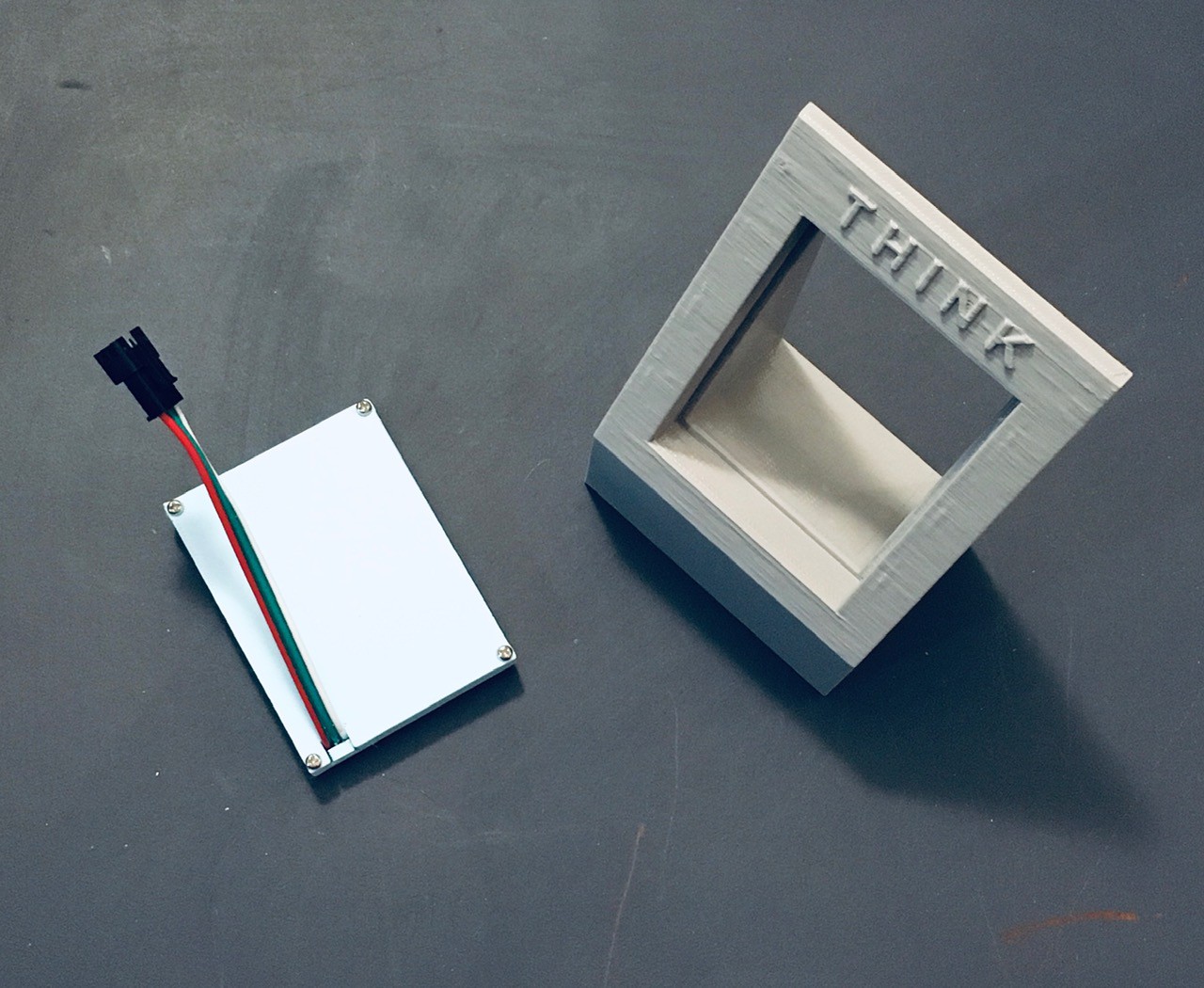
I designed an enclosure for the project. Here is a photo of everything required to make a Think-a-Tron Mini.
The GM67 unit and the OLED display slide into the slots provided behind the front panel. I printed some tabs to hold the display in place and used a small piece of two sided tape to secure the GM67. The front of the scanner should be flush with the front of the panel.
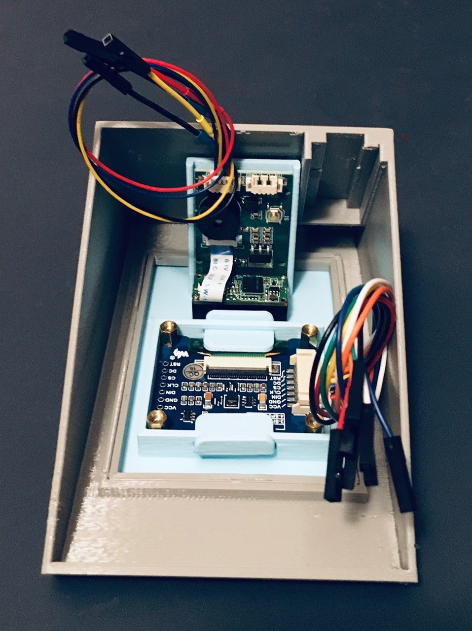
There is also a spot for the Nano to nest. I anchored it in place with two sided tape.
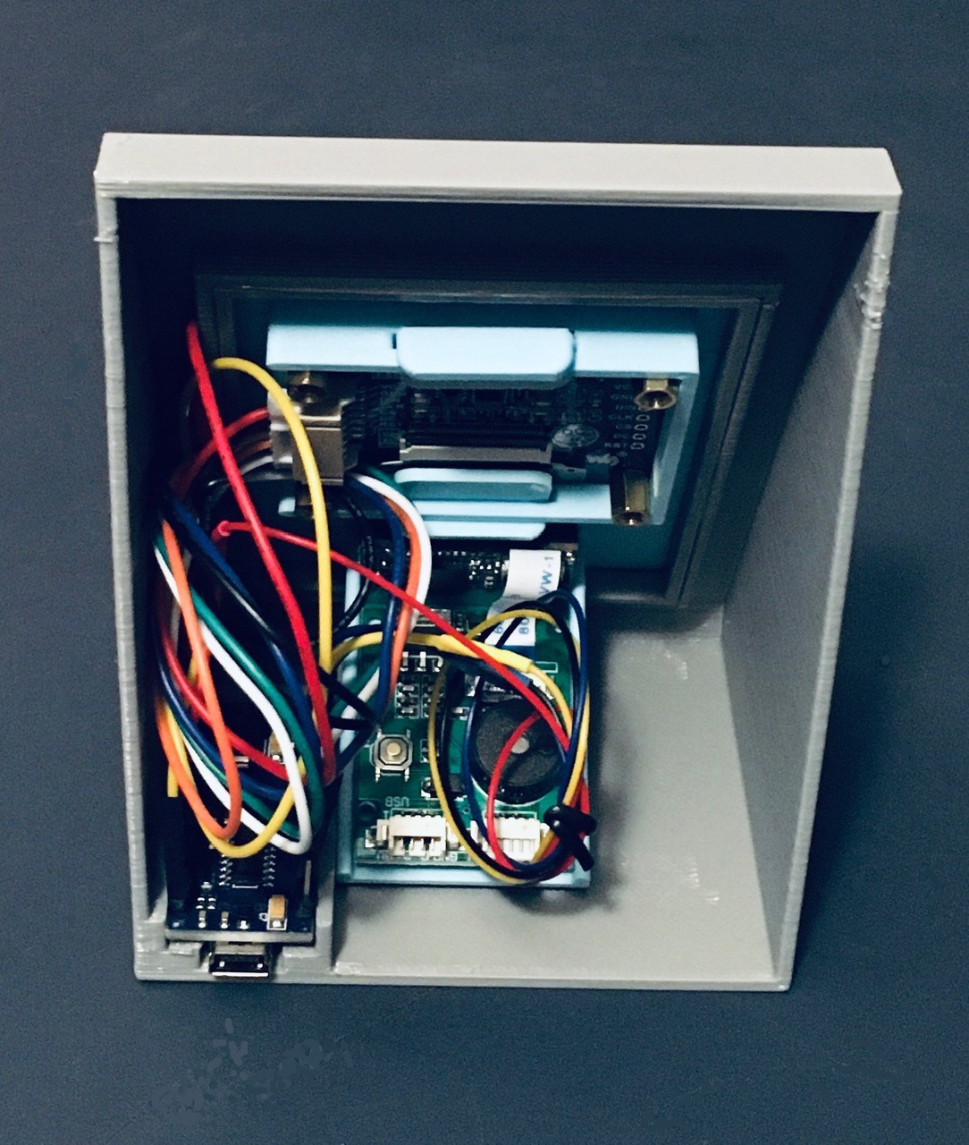
The wiring looks a bit messy but is actually pretty straight forward.
| From | To Arduino |
|---|---|
| GM67 VCC | 5V |
| GM67 TX | D2 |
| GM67 RX | D3 |
| GM67 GND | GND |
| OLED VCC | 3.3V |
| OLED GND | GND |
| OLED DIN | D11 |
| OLED CLK | D13 |
| OLED CS | D10 |
| OLED DC | D7 |
| OLED RST | D8 |
And that's it. It doesn't get much more minimalistic than this.
The only tweaks I made to the GM67's default factory settings were to:
- Change the scanning mode from continuous to one where it detects the presence of a card before scanning based on lighting changes. This seems to work pretty well.
- Disable the LED light on the front of the unit. The light was pretty bright and it's not necessary for most situations
This was done by scanning in the appropriate QR codes from the manual of course. So cool.
All that's left to do is to load the Arduino sketch onto the Nano. The sketch can be found on github. See Think-a-Tron Mini.
It's All In the Cards
For Think-a-Tron 2020 and Mini versions, standard business sized cards (3 1/2 x 2 inches) are used to hold the trivia questions. The questions, multiple choice or true and false, are printed on the front, and the correct answer is printed as a QR code on the back.
For Think-a-Tron Mini I created a new version of the Python script from Think-a-Tron 2020 that was used to create trivia cards and made a couple of changes.
- Since I am not limited to using physical buttons on the Mini version I have increased the number of optional trivia question choices to five from three.
- Also, the GM67 has no problems reading Python generated QR codes (as the ESP32-CAM implementation did), so I obfuscated the payloads for the question cards to prevent a player from figuring out the answer just by looking at the QR codes (hard but doable without the obfuscation).
So the application works with one sheet of Avery 5371 business cards at a time. You simply key in ten questions, choices, and answers then press the Save button. This will create:
- A text file with your data so that you can Load it back in to make changes.
['Humans and chimpanzees share roughly how much DNA?', 'Roughly how long does it take for the sun’s light to reach Earth ?', 'At what temperature are Celsius and Fahrenheit equal?', 'What modern-day country was Marie Curie born in?', 'How many hearts do octopuses have?', 'Apollo 15 was the first moon mission to carry a lunar rover?', 'On the periodic table, what symbol stands for silver?', 'Mercury is the only planet in the solar system without a moon.', 'What was the name of the first man-made satellite launched by the Soviet Union in 1957?', 'What is the biggest planet in our solar system?'] ['10%', '8 minutes', '-40', 'Hungary', 'One', '', 'Si', '', 'Sputnik 1', 'Uranus'] ['52%', '8 hours', '0', 'Poland', 'Two', '', 'Ag', '', 'Echo 1', 'Jupiter'] ['98%', '8 days', '32', 'Czechoslovakia', 'Three', '', 'Na', '', 'Explorer 1', 'Neptune'] ['', '', '', '', '', '', '', '', '', ''] ['', '', '', '', '', '', '', '', '', ''] [3, 1, 1, 2, 3, 4, 2, 5, 1, 2]
- A PDF of the questions and choices nicely formatted one per card.
- A PDF of the ten QR codes laid out to align with the correct questions when two sided printing.

In addition for the Mini version I created a second Python application to make "control" cards. As with the trivia questions, the application works with one sheet of Avery 5371 business cards at a time.
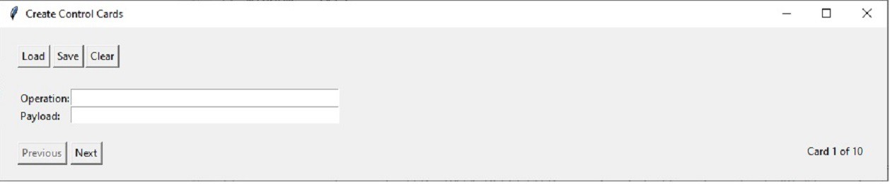
I used this application to make seven cards for each player that allow them to "scan in" their guesses ("A", "B", "C", "D", "E", "T", "F"). I also made cards to control the operation of the game. For instance to reset the scores to zero and start a new game, or disable the animation when showing an answer.
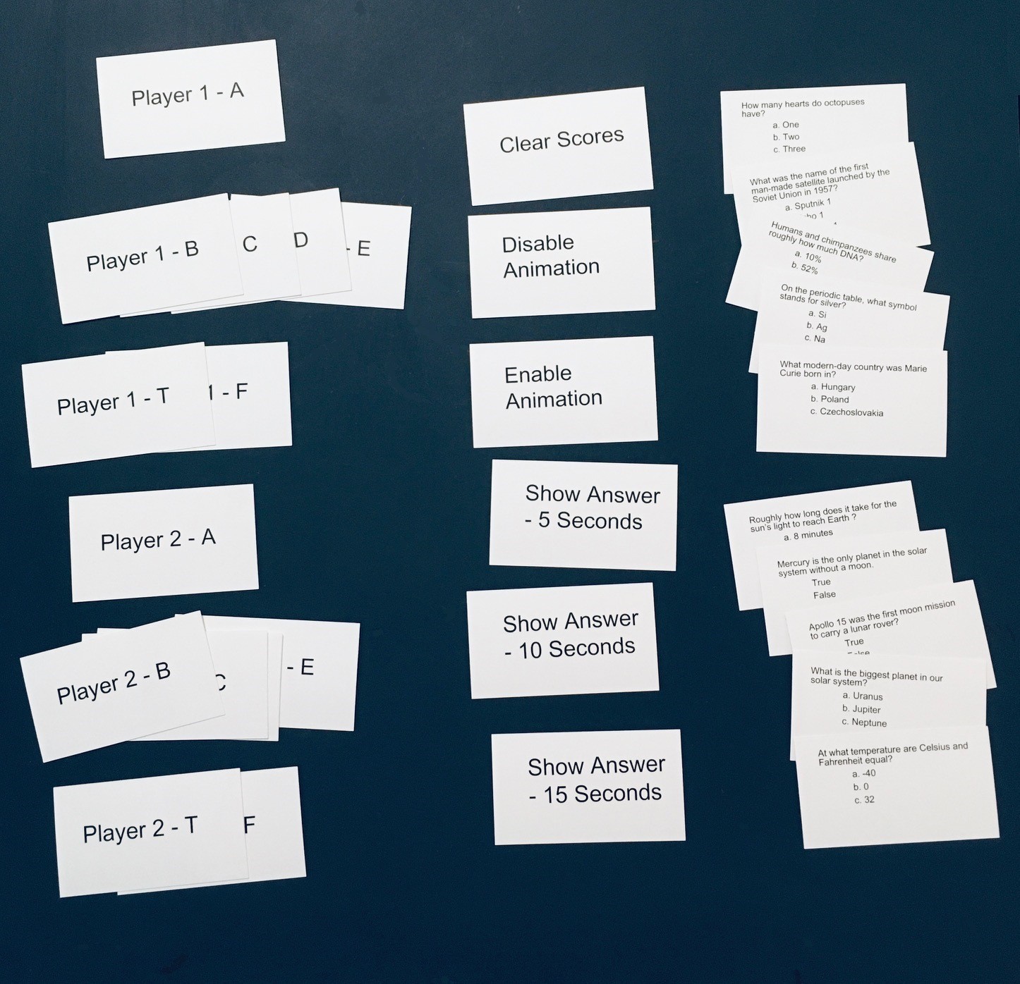
Each control card payload is a simple 3 character command string:
| Player Answer Cards | P1A, P1B, P1C, P1D, P1E, P1T, P1F, P2A, P2B, P2C, P2D, P2E, P2T, P2F |
| Game Control Cards | Cxx - where xx is an operation number (00, 01, 02, etc.) |
| Answer Cards | Axx - where xx is a slightly obfuscated code representing the answer (A, B, C, etc.) |
Here is a look at all three types of cards.
The Python scripts for both these applications can be found on github. See: Think-a-Tron Mini.
Would You Like To Play a Game?
So with the Think-a-Tron Mini, playing a game goes something like this.
- Someone reads the question from a trivia card.
- Both players lock their answers into Think-a-Tron Mini by scanning the appropriate player card with the letter of the choice they want. They can change their mind and scan a different card if they want.
- The answer card is scanned into Think-a-Tron Mini, which is "activated" and reveals the correct answer after a short optional animation.
- Think-a-Tron 2020 automatically increments the score for those players with the correct answer. Correct answer guesses are highlighted in green on the display and incorrect guesses in red.
- After a short configurable time interval the screen resets for the next question with the ? appearing.
- Repeat.
I made a little demo video of Think-a-Tron Mini in action.
Final Thoughts
The GM67 was my inspiration for this build. I chose to use it in a follow up to my Think-a-Tron 2020 project. But I am sure that there are many other applications for which this relatively simple piece of hardware could be employed.
For three days of effort I am super happy with the result.