Close
0%
0%

VFD watch

bringing an old VFD back to life

Public Chat
Similar projects worth following
I'm working on a VFD watch.
This is my first try with this type of display. It must be fun and i'll learn a lot.

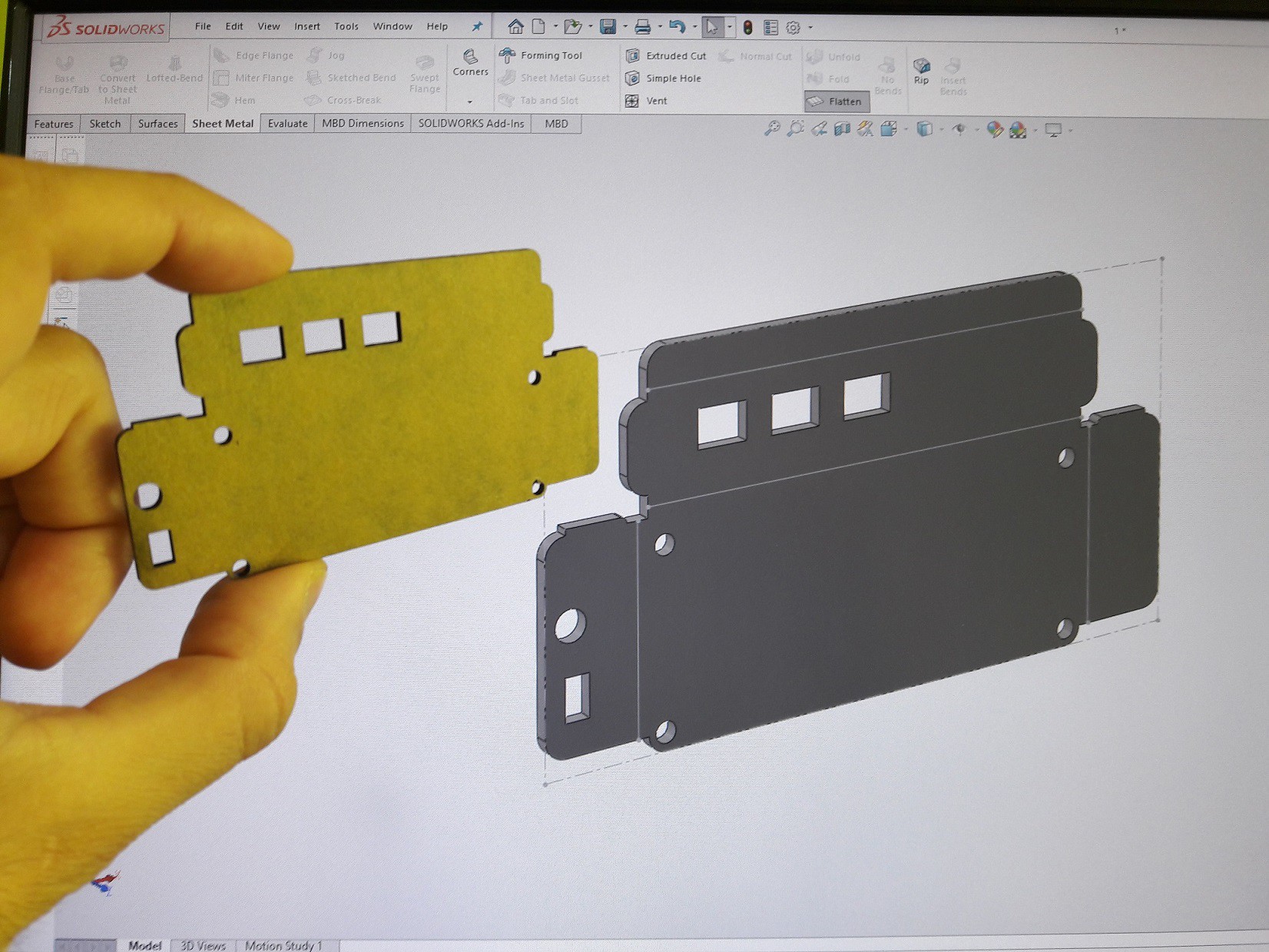
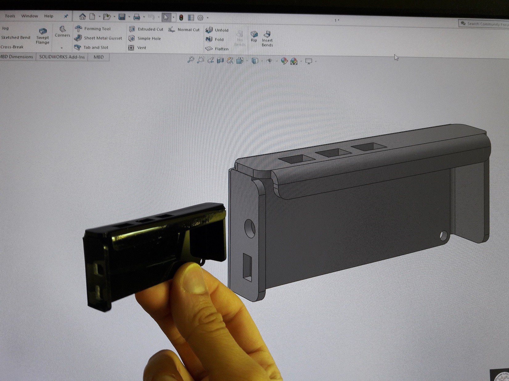
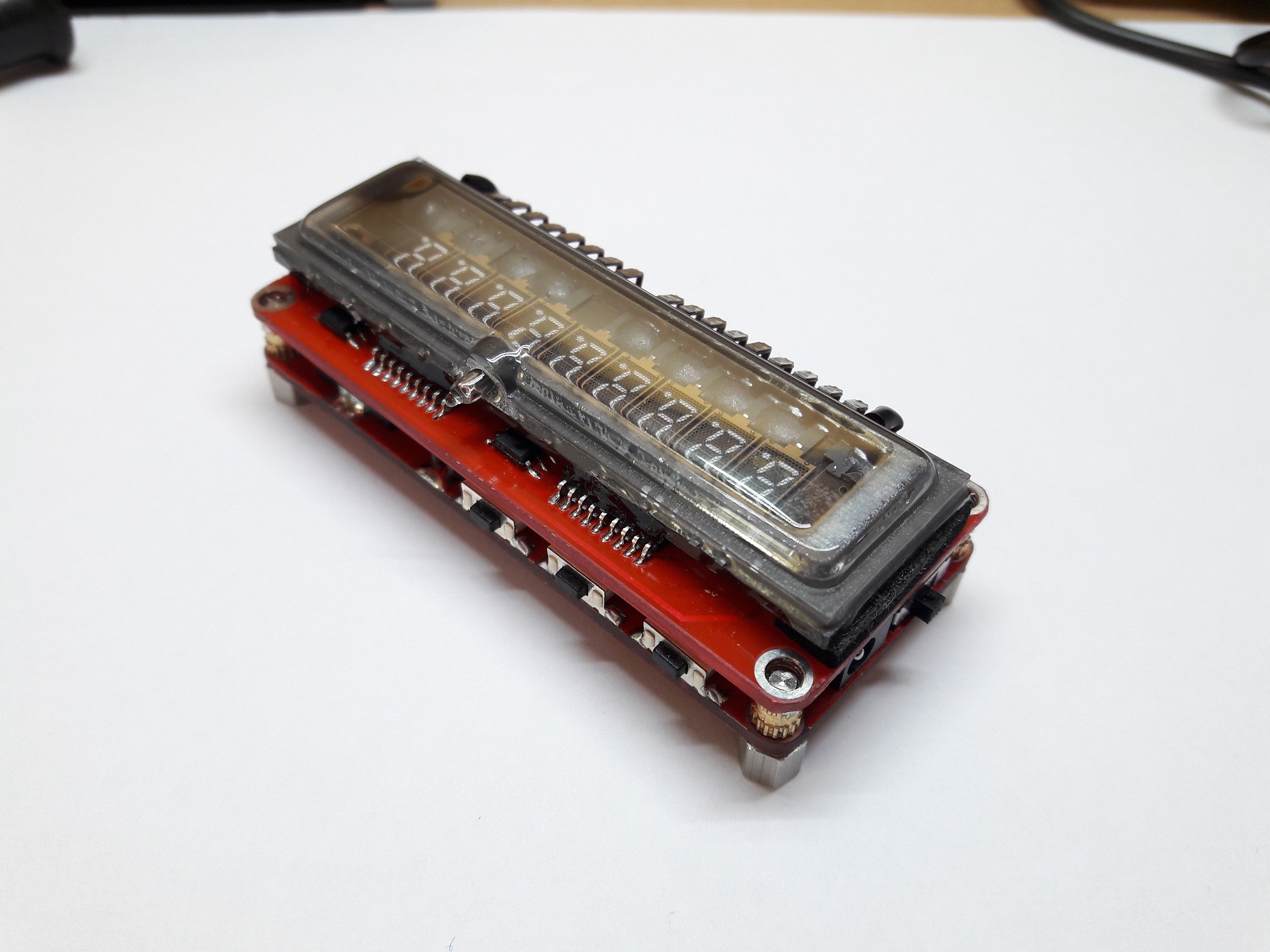
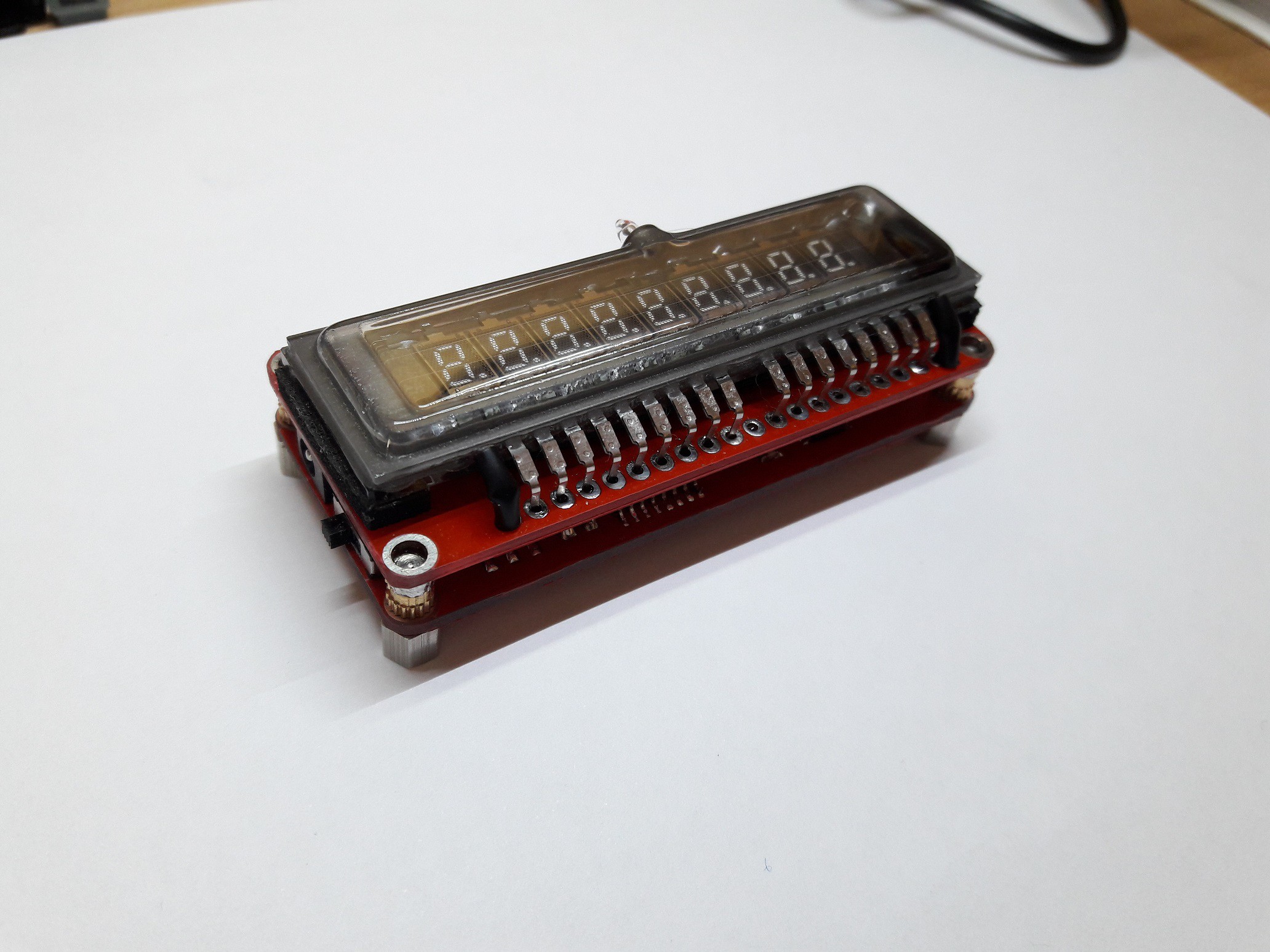
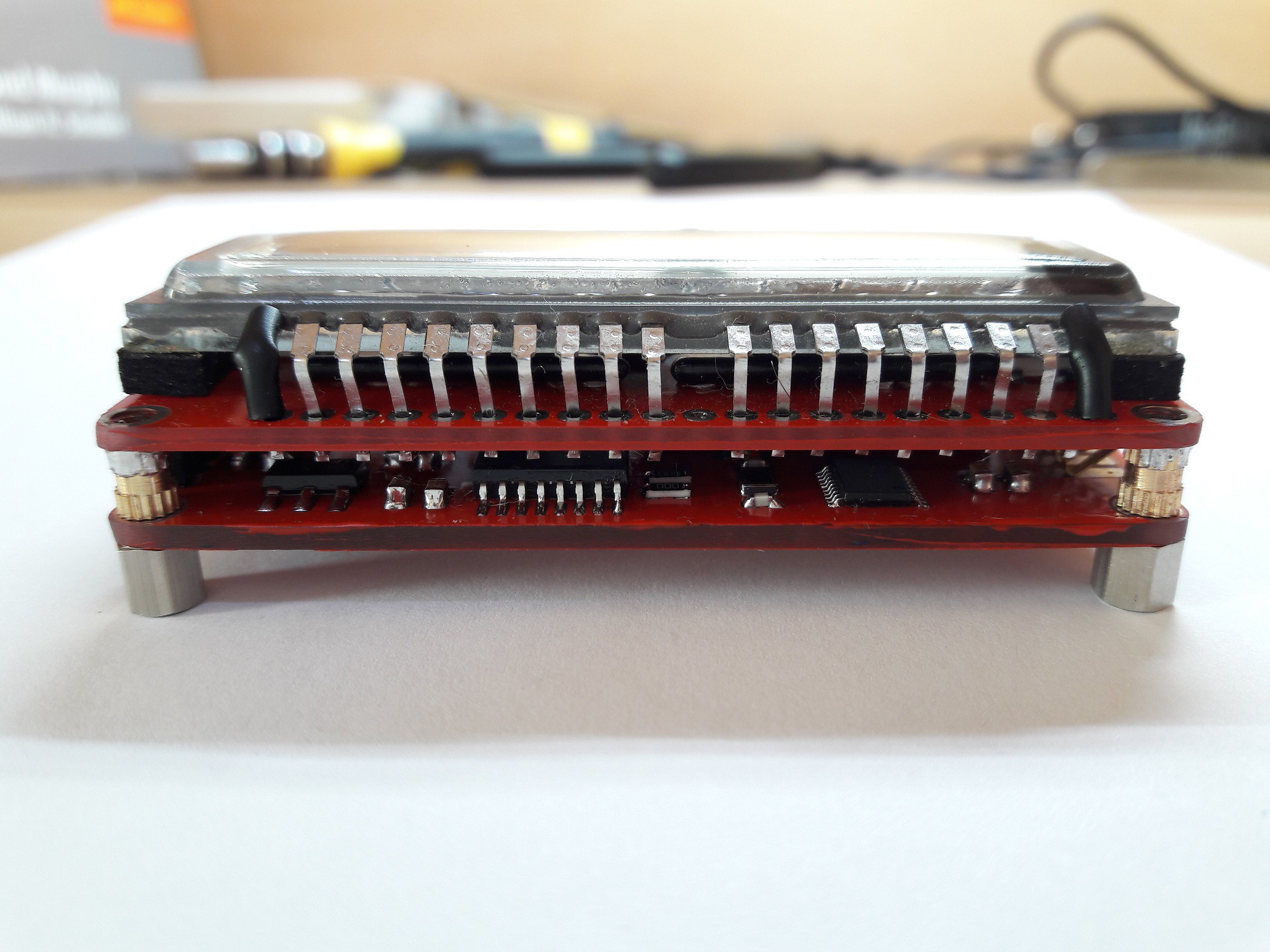
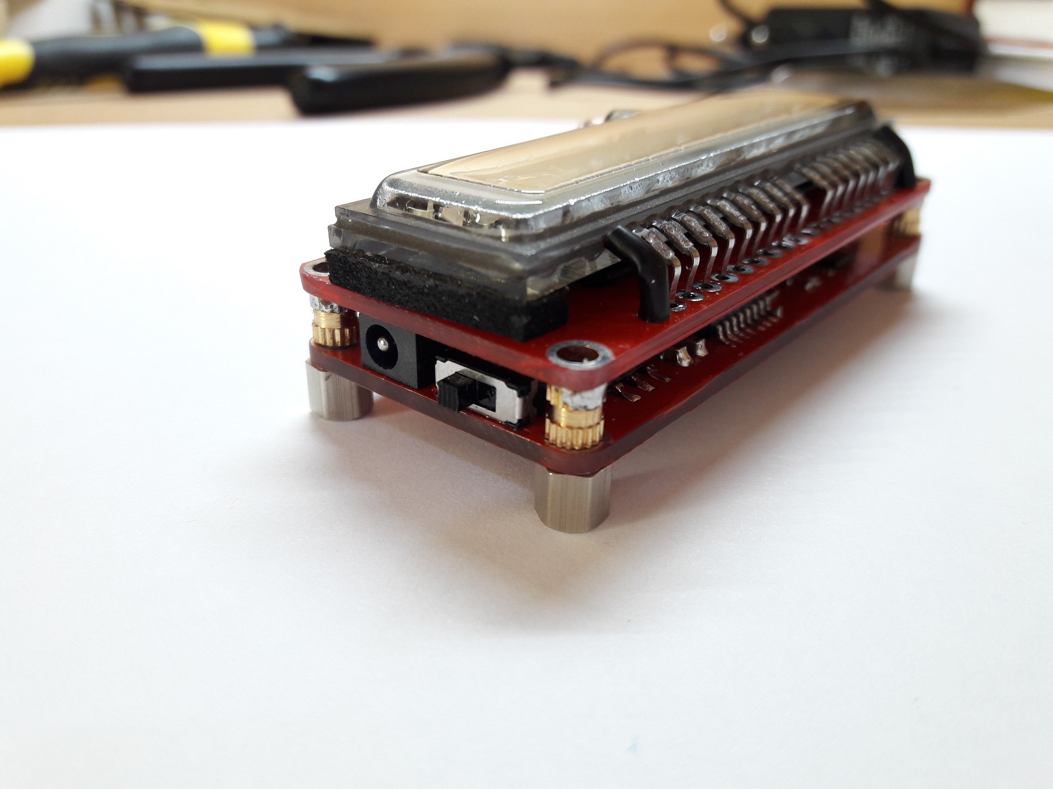
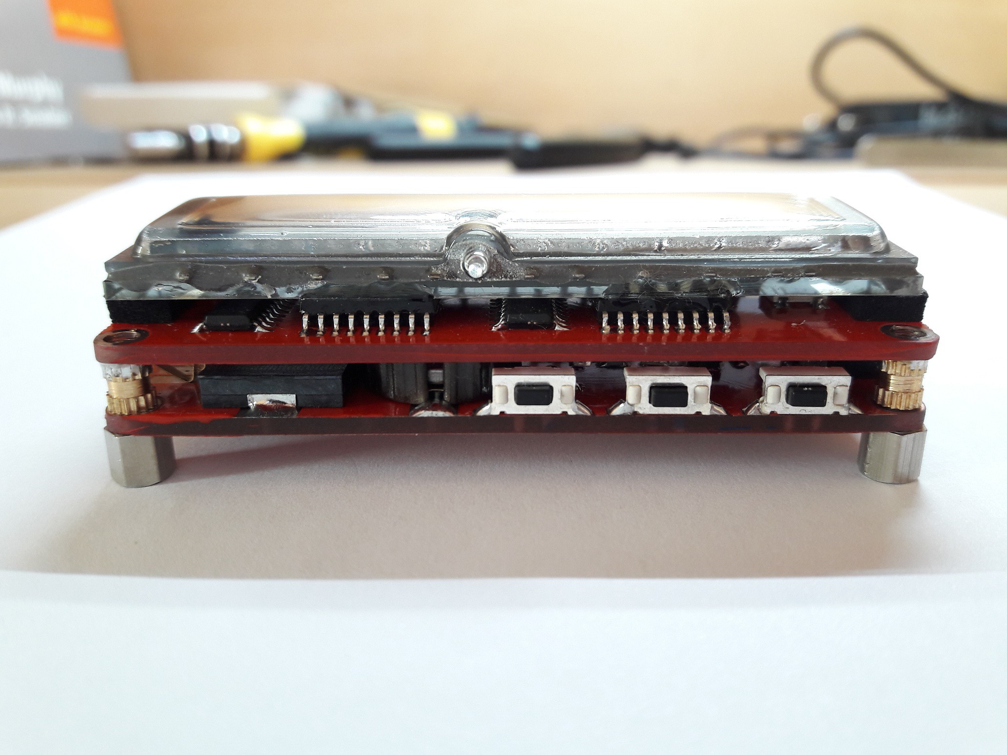
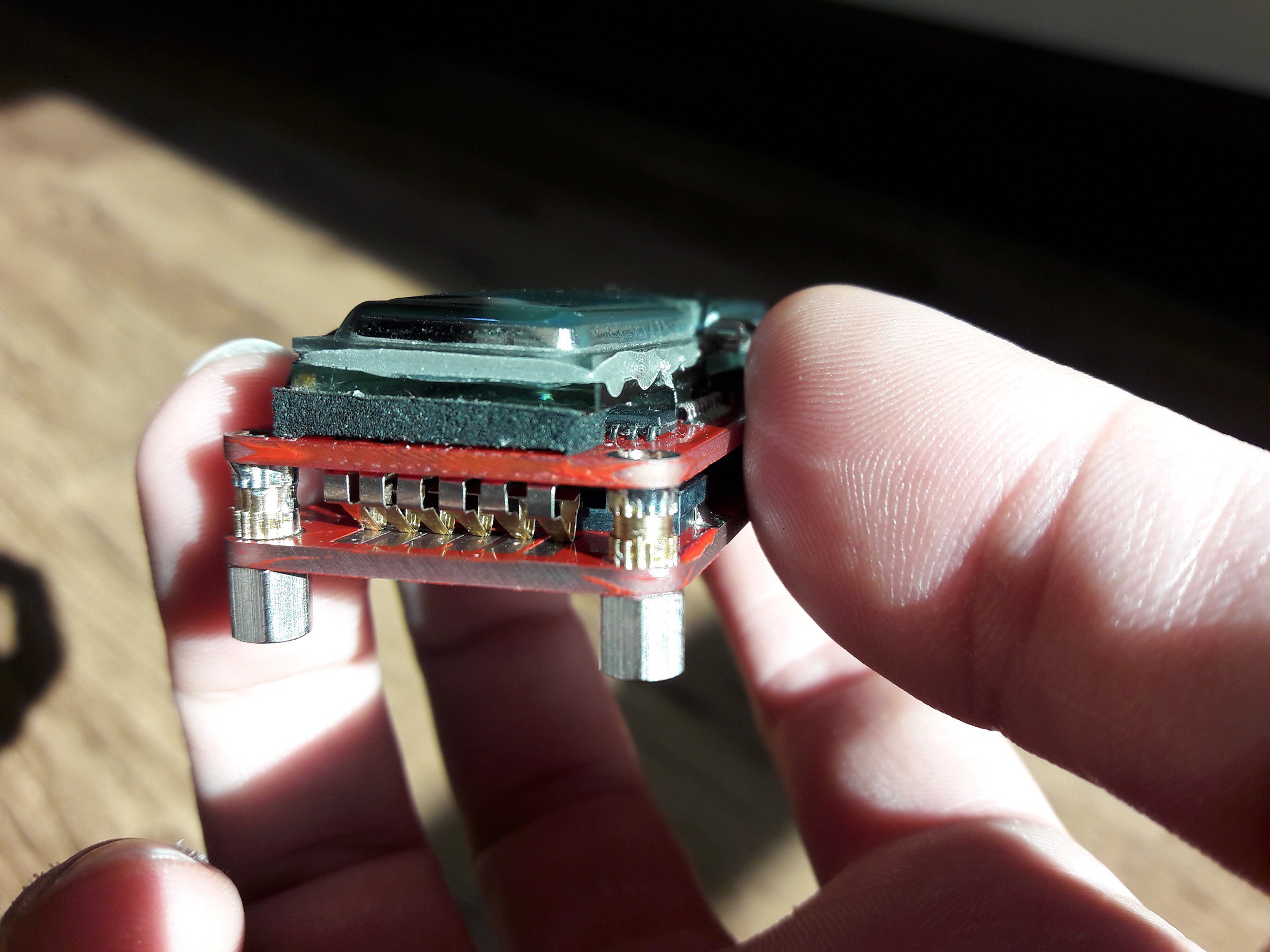
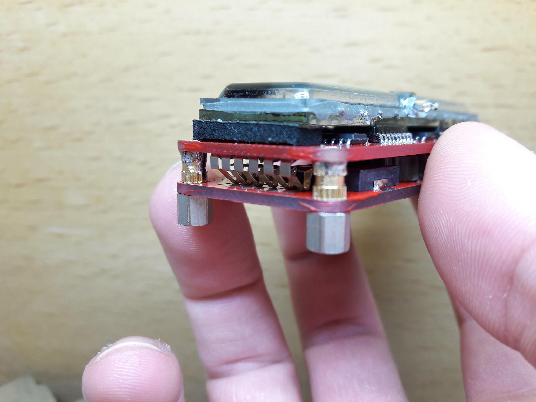
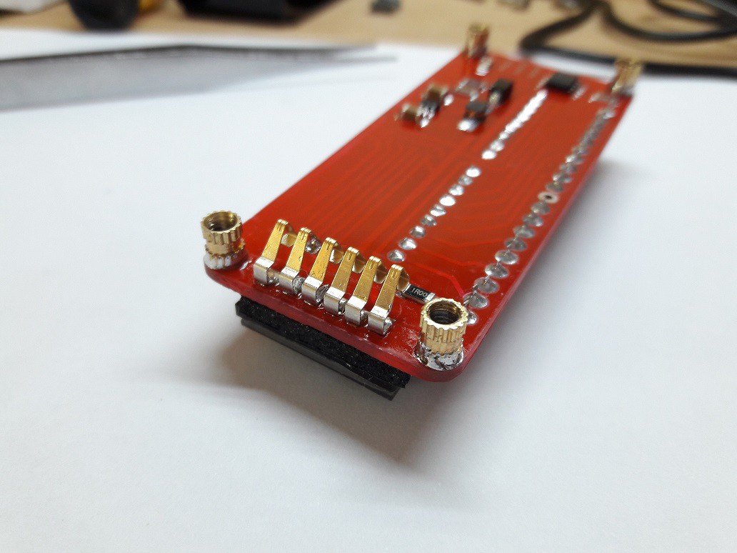
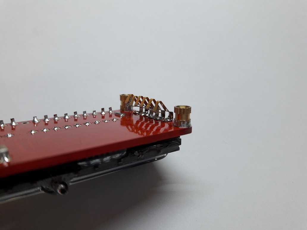
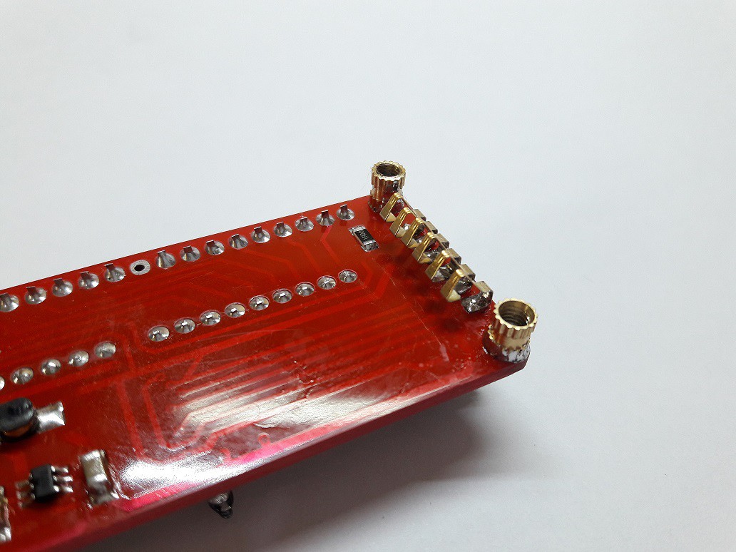
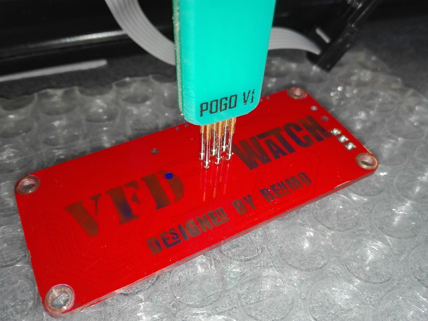
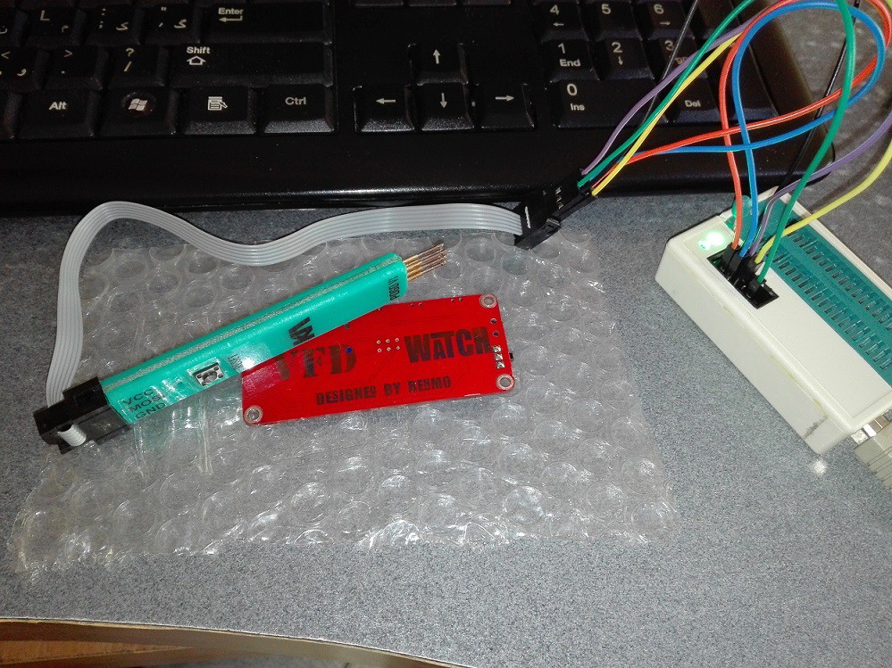
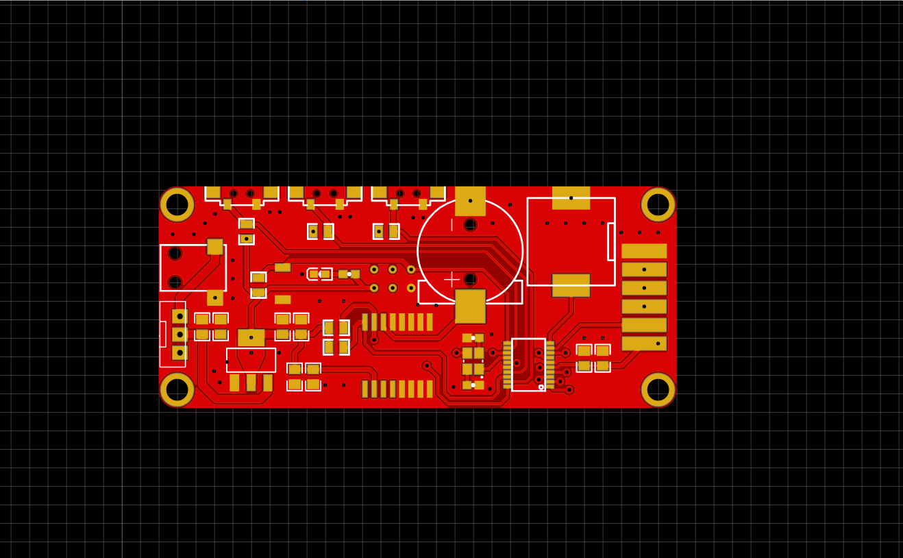
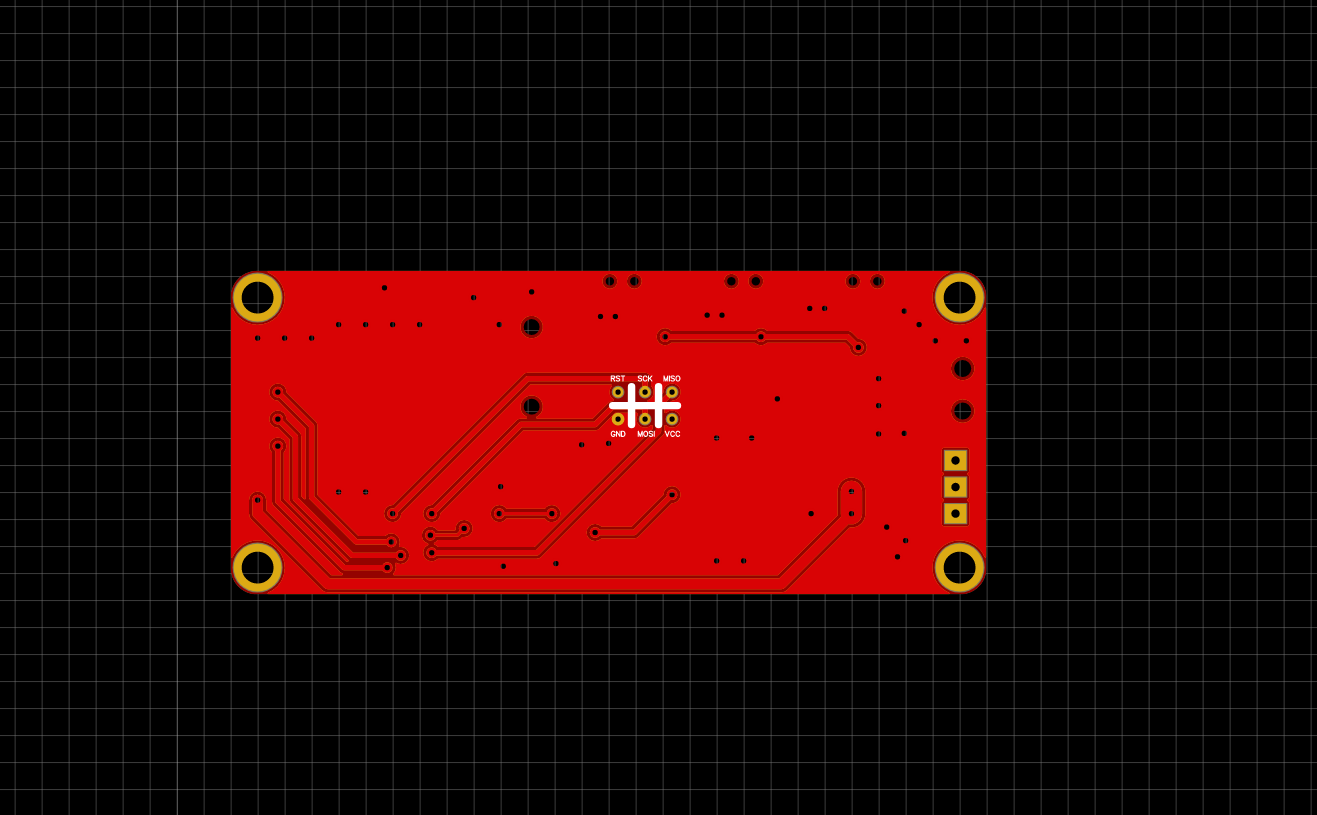
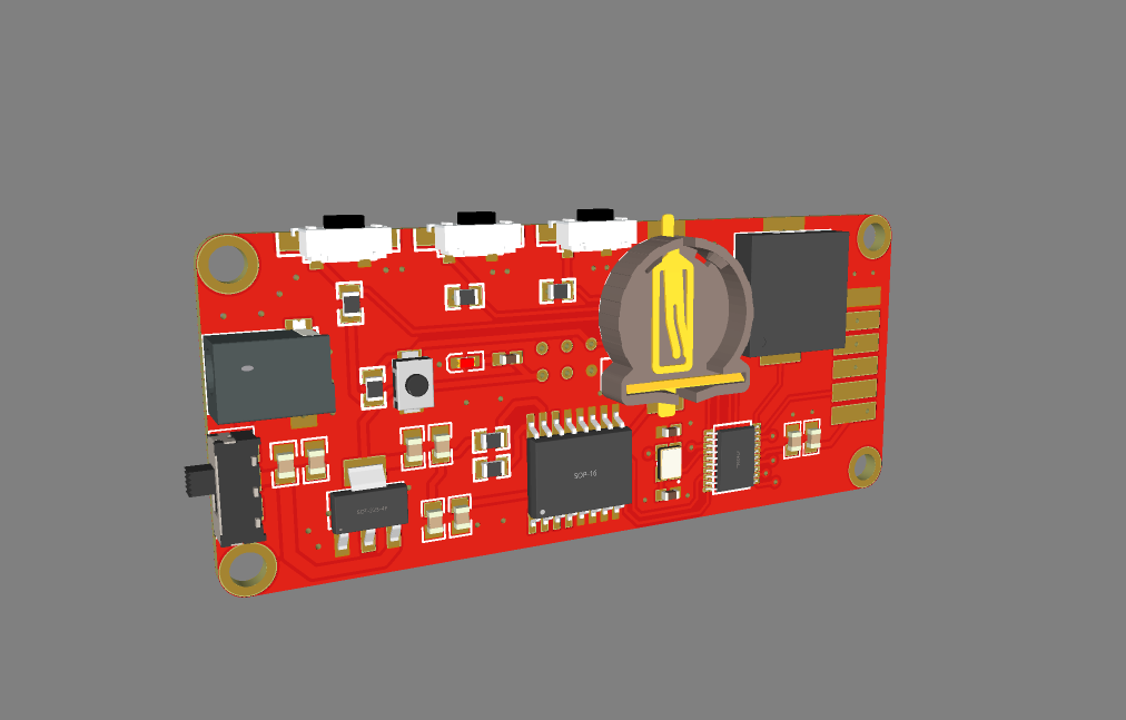
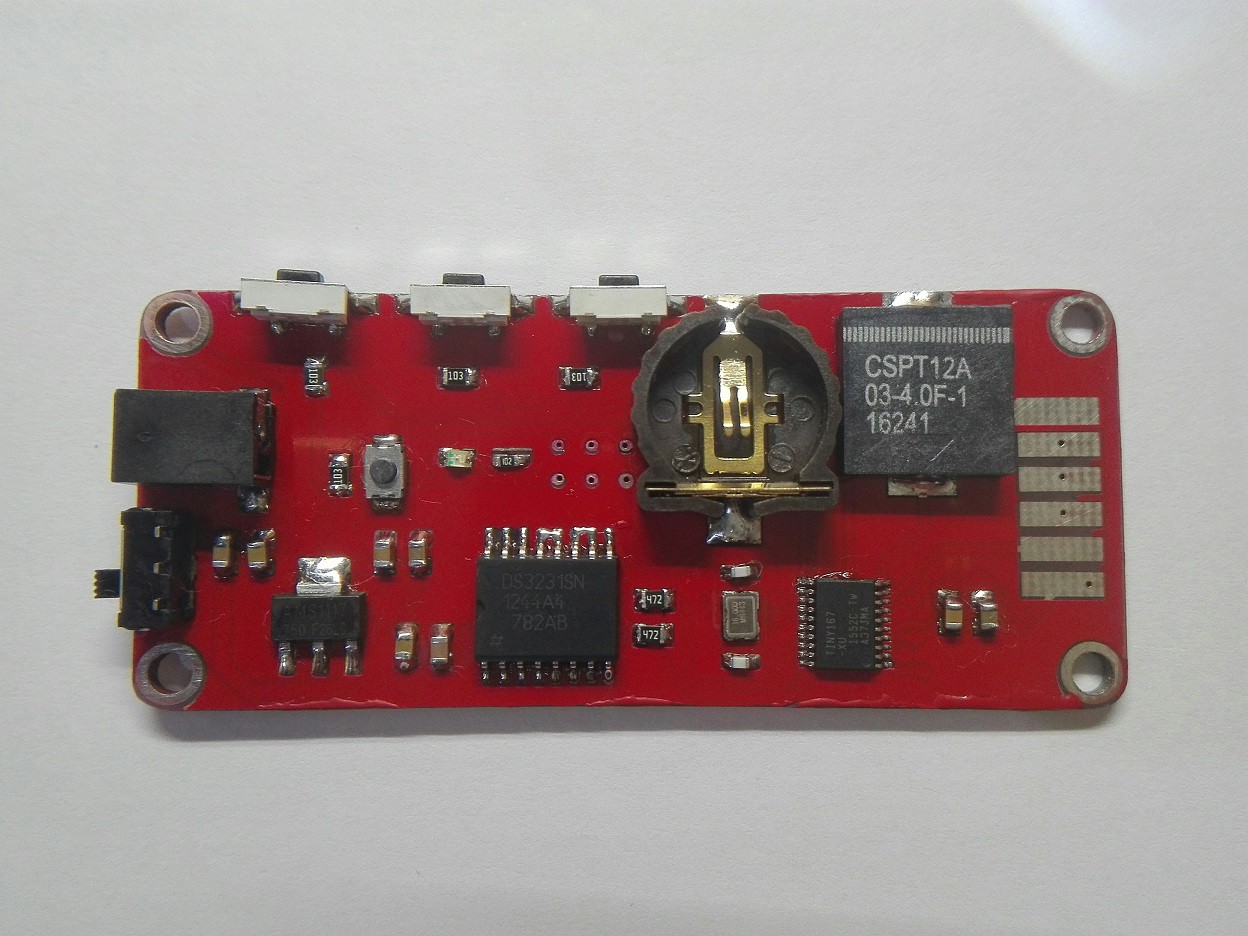
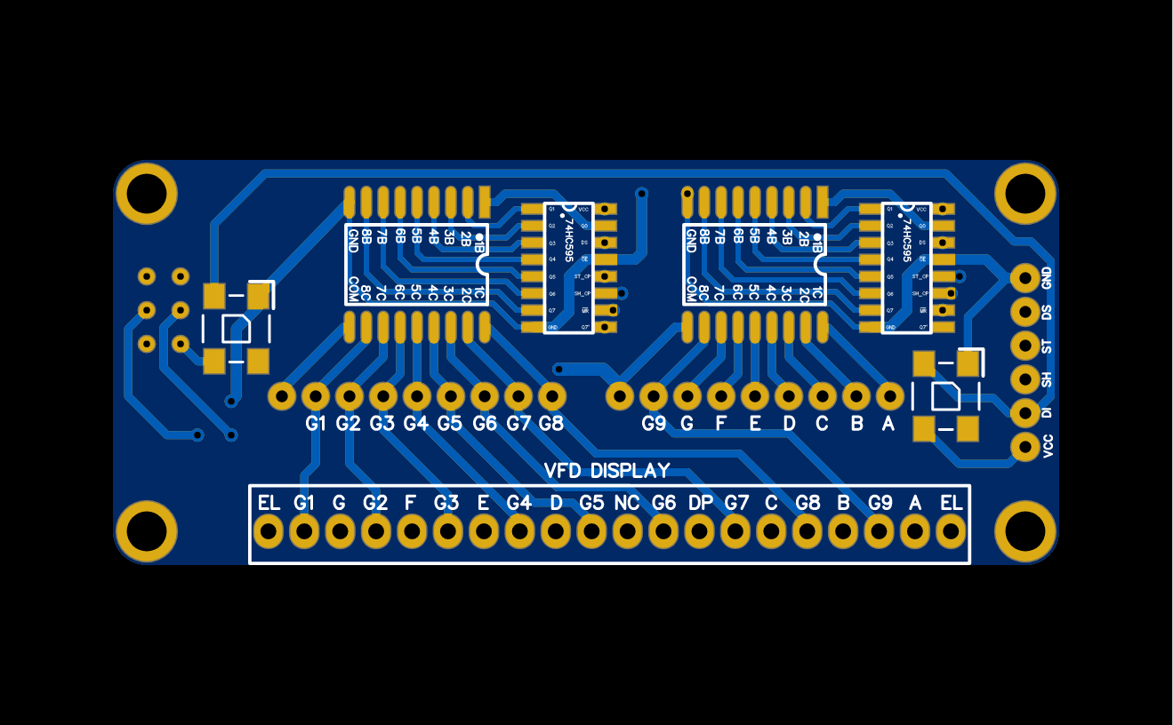
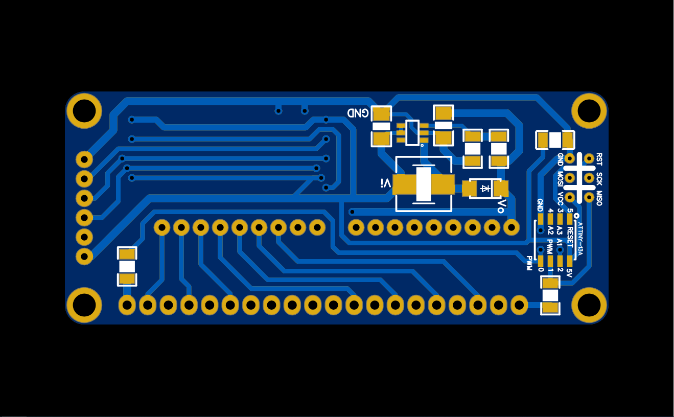
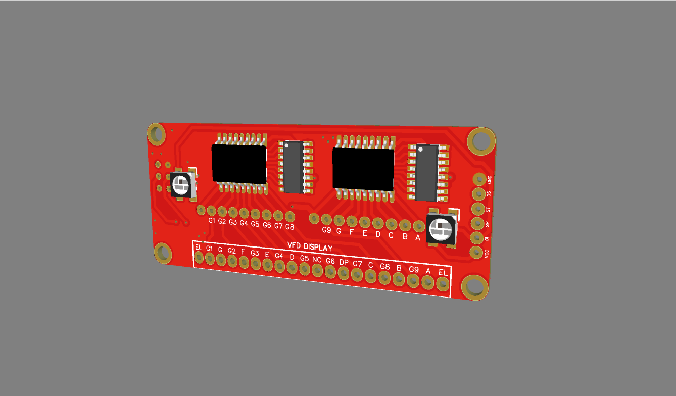
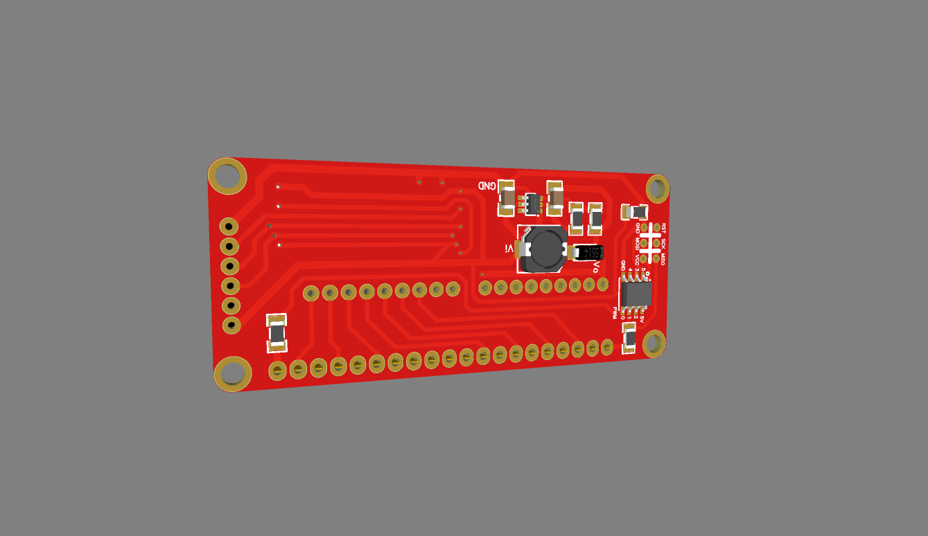
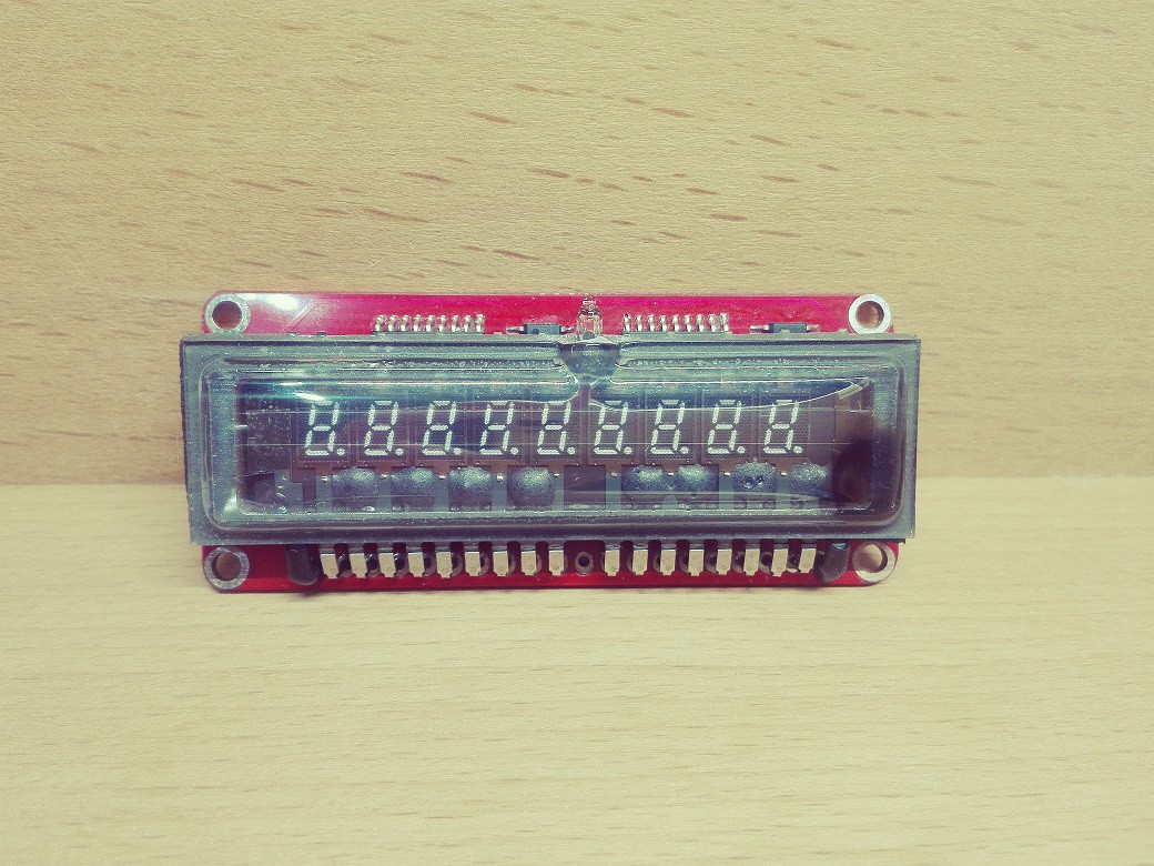
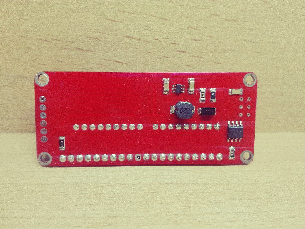
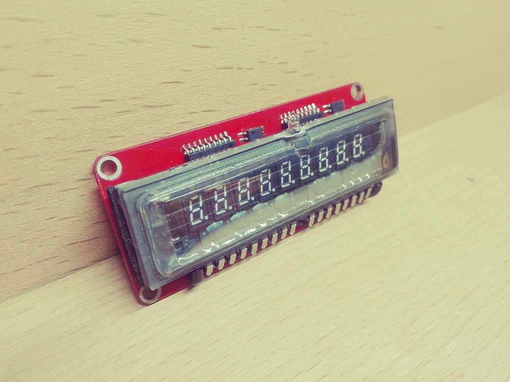
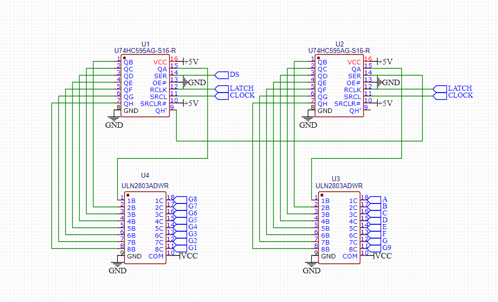
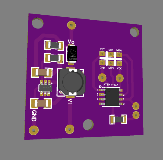
This is a VFD based watch and consist two major parts. First part is VFD breakout board it has parts to provide VFD required 28v dc voltage and 5v ac voltage. also the ULN2803 and 74HC595 ICs allow to control whole VFD with 3 pins. Second part is VFD controller board it has a RTC , microcontroller , buzzer and all other parts that complement the first part and form a WATCH...

VFD_DigiPro_V4.ino.pro.hex

upload the hex file to your ATTiny167 microcontroller

hex - 31.47 kB - 01/02/2021 at 11:24

Download

cover.DXF

laser cut cover

AutoCAD DXF - 33.09 kB - 01/02/2021 at 09:21

Download

pcbdoc - 367.00 kB - 12/28/2020 at 20:52

Download

Adobe Portable Document Format - 74.27 kB - 12/28/2020 at 20:52

Preview
Download

VFD breakout board-SMD.pcbdoc

VFD breakout board

pcbdoc - 309.00 kB - 12/24/2020 at 18:10

Download

View all 7 files

  • 1 × MT3608 DC-DC boost converter IC
  • 1 × 22uh inductor
  • 1 × SS34 Discrete Semiconductors / Diodes and Rectifiers
  • 1 × 2.2k 1206 resistor
  • 1 × 100K 1206 resistor

View all 27 components

  • Cover

    Ben Mo01/02/2021 at 09:16 0 comments

    I've designed and made a cover for VFD watch...

  • Parts come together

    Ben Mo12/31/2020 at 09:30 0 comments

  • Breakout Board Connector

    Ben Mo12/31/2020 at 08:25 0 comments

    Unfortunately i couldn't find a suitable connector for my purpose...So i decided to make it.

    I ordered some Nokia 3110 battery connector to extract their flexible pins.These pins have the exact height that i need.

    Also, I soldered M3 brass insert nuts as on-board spacer to avoid using extra screws when i'll assemble the parts

  • Programming Time

    Ben Mo12/31/2020 at 07:43 0 comments

  • VFD Controller Board

    Ben Mo12/28/2020 at 20:51 0 comments

    This is the controller board that has a DS3231 RTC chip , an Attiny167 microcontroller , a Buzzer and some other component...

  • VFD breakout board

    Ben Mo12/24/2020 at 18:06 0 comments

    I've designed this board for my VFD. it consists of a boost converter based on MT3608 , AC voltage provider with ATTiny13 microcontroller , ULN2803 and 74HC595 ICs to control all grids and segments with 3 pins and also has two ws2812b RGB led as backlight especially used in alarm clock feature.

  • VFD controling method

    Ben Mo12/24/2020 at 16:19 0 comments

    I used combination of ULN2803 and 74HC595 to control all VFD just using 3 pins.

  • MT3608 & ATTiny13 test PCB

    Ben Mo12/24/2020 at 15:57 0 comments

    Testing boost voltage circuit with fixed output voltage also program and test Attiny13 to provide a 5v ac voltage for VFD filament.

  • Filament AC voltage

    Ben Mo12/24/2020 at 15:51 0 comments

    For filament we can use DC or AC voltage but AC has superiority over DC. If the filament is driven with a DC voltage there will be a voltage gradient across its length. This means the end of the display with the more positive filament voltage will have less of a differential to the anodes, and thus will be dimmer than the negative end of the filament due to the potential gradient effect.

    http://insanity4004.blogspot.com/2017/03/p170-dh-vacuum-flourescent-display.html

    https://www.qsl.net/m0ayf/VFD-Regen.html

    to producing AC voltage i decided to use a microcontroller, in this case i choose an Attiny13 .

    for achieving a 5v 60hz ac voltage i programmed two pins of Attiny13 as output and switching them on/off respectively with a 8 milliseconds delay.

    void setup() {
    
      pinMode(0, OUTPUT);
      pinMode(1, OUTPUT);
    
    }
    
    void loop() {
      digitalWrite(0, HIGH);
      digitalWrite(1, LOW);
      delay(8);
      digitalWrite(0, LOW);
      digitalWrite(1, HIGH);
      delay(8);
    }

  • MT3608 circuit test pcb

    Ben Mo12/24/2020 at 14:22 0 comments

    It works fine and boost 5v up to 28v

View all 12 project logs

Enjoy this project?

Share

Discussions

Vlad V wrote 01/28/2022 at 18:26 point

Im going to make my own out of an Triumph-Adler 80c
it uses the same display, but i have the whole calculator including the power supply so i'll just modify that. I hope to use a teensy microconroler to control it.

  Are you sure? yes | no

Paul Andrews wrote 05/24/2021 at 18:47 point

I'm just developing my own VFD board and the MT3608 looks like an interesting alternative to the design I came up with on webench. What was the spec of the 22uH inductor you used?

  Are you sure? yes | no

Ben Mo wrote 05/25/2021 at 03:45 point

your works are great and i excited to see your new design.
I've used CD54 and CD32 for 22uH inductor and both work great.

  Are you sure? yes | no

Mitsuru Yamada wrote 01/02/2021 at 12:30 point

Nice project ! In the 1970s, my home calculator was a VFD with a beautiful green display.

  Are you sure? yes | no

Ben Mo wrote 01/02/2021 at 14:02 point

Thank you dear @Mitsuru Yamada 
"old is gold"...  i'm agree with you these displays are so beautiful

  Are you sure? yes | no

Ben Mo wrote 12/31/2020 at 07:32 point

Thanks dear @Mike Szczys 
The controller board has an AMS1117-5v regulator that feeds whole the device.a 9v/1a dc adapter plugs into dc jack and supplies the input voltage of AMS1117.

  Are you sure? yes | no

Mike Szczys wrote 12/30/2020 at 23:15 point

I'm quite interested to see this one come together. What power source will feed the boost converters for the VFD?

  Are you sure? yes | no

Similar Projects

Does this project spark your interest?

Become a member to follow this project and never miss any updates