 Michael Zhang
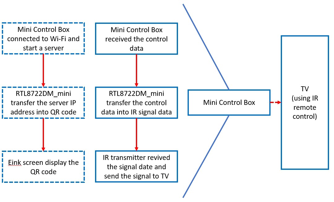
The block diagram comes first before starting the project.
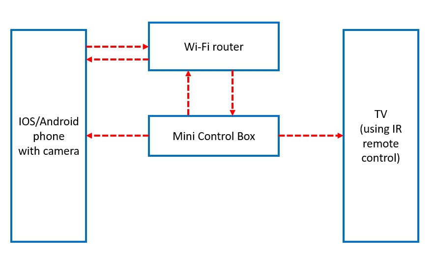
The whole system is shown above. This is a contactless system all data is transferred by wireless. Phone and mini control box required to connect the same WiFi. There is an E-ink screen on the box that used to display the QR code of the server IP after connected with WiFi. The phone then scans the QR and uses the link to visit HTML UI to control the TV.
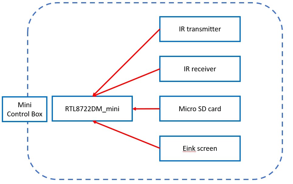
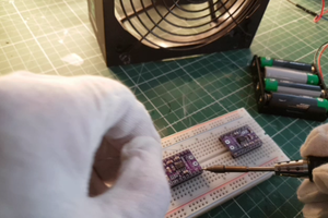
Below is the hardware of the box.
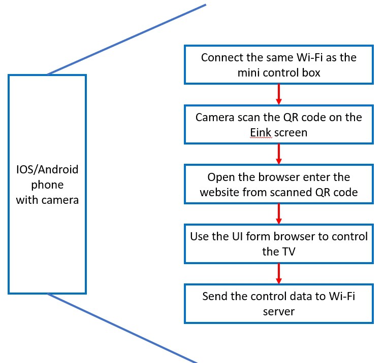
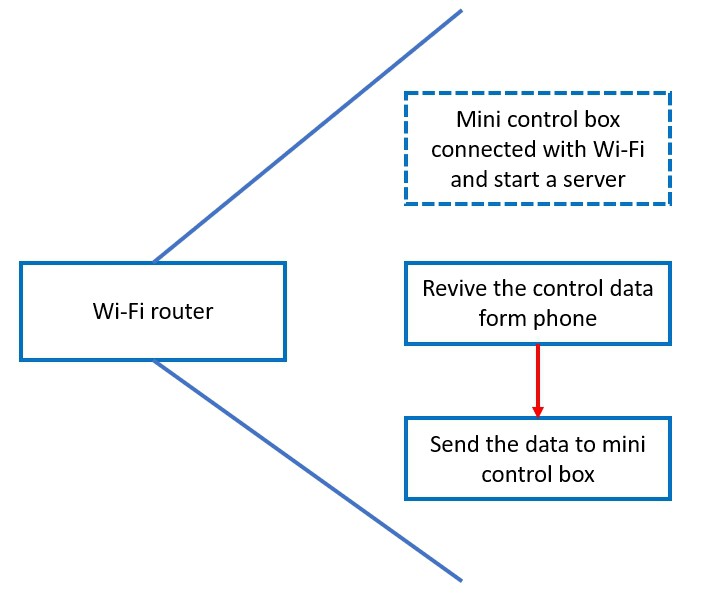
The following pictures are the process of the system. The dotted box is the pre-request of the process.
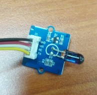
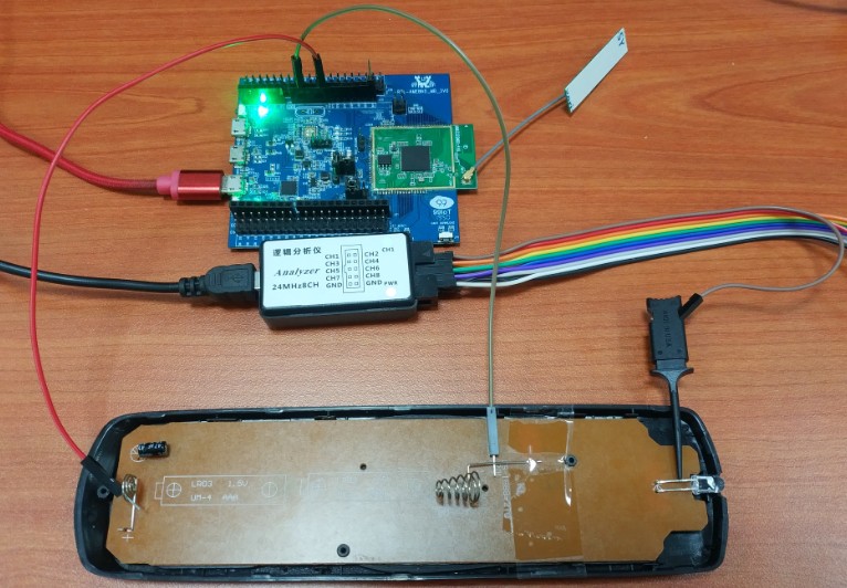
The first part is to get the signal from the target TV controller.
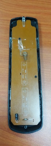
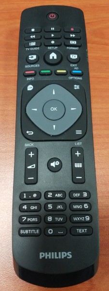
the remote controller has a very simple circuit. We can easily get the IR signal from the IR sensor (the LED) positive PIN with power the controller by 3 volts.
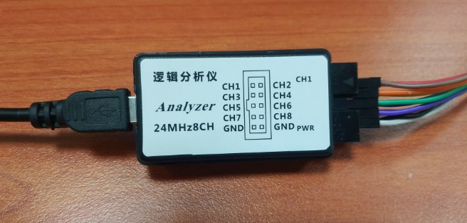
the measure the signal, I use the logic analyzer. It is simply a connection with USB to PC to monitor the signal.
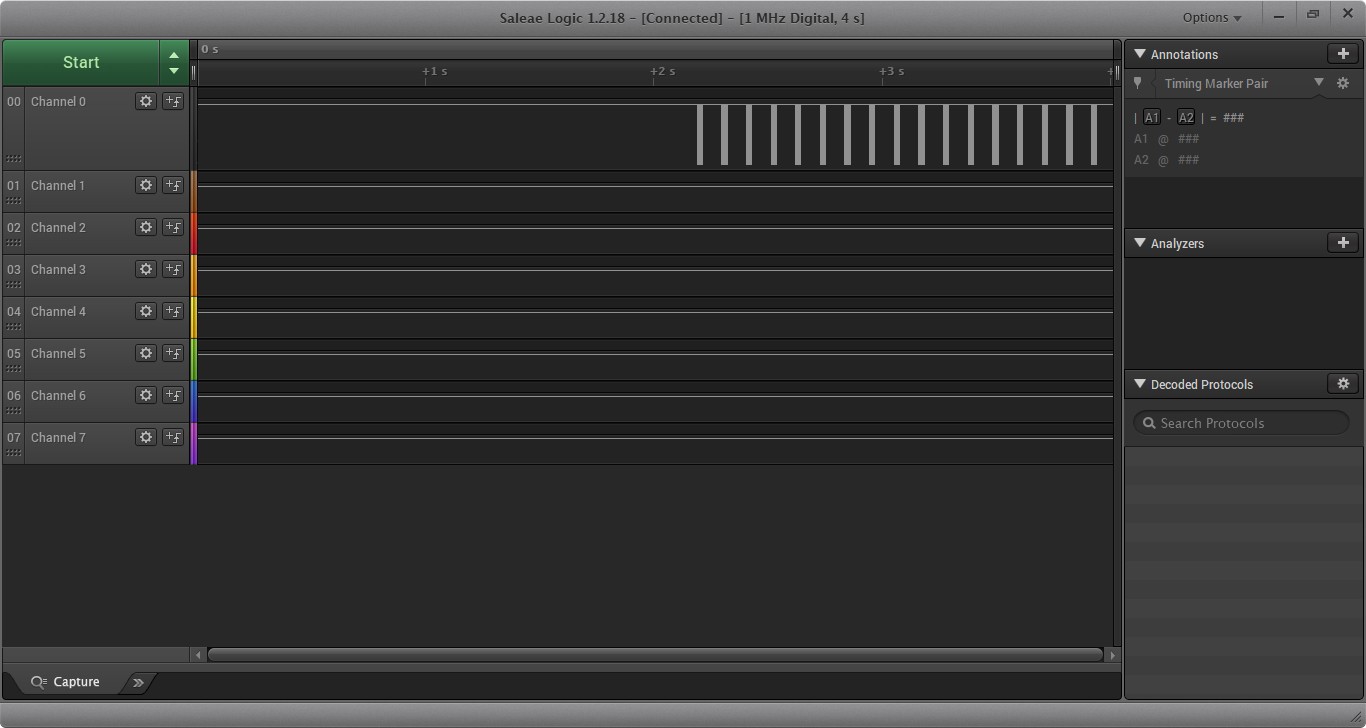
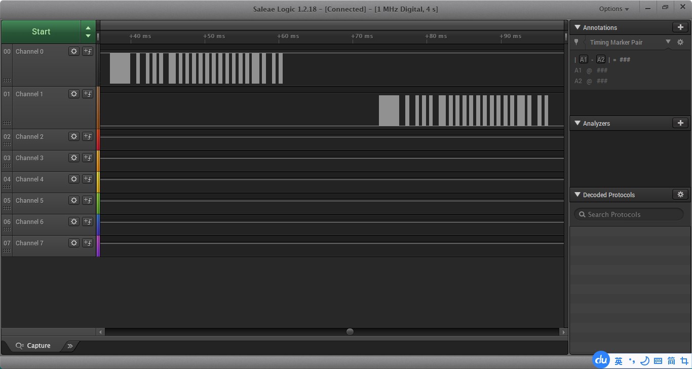
above it the power button from my measurement. each group of the signal represents a press of the POWER button. In this case, I just hold the button.
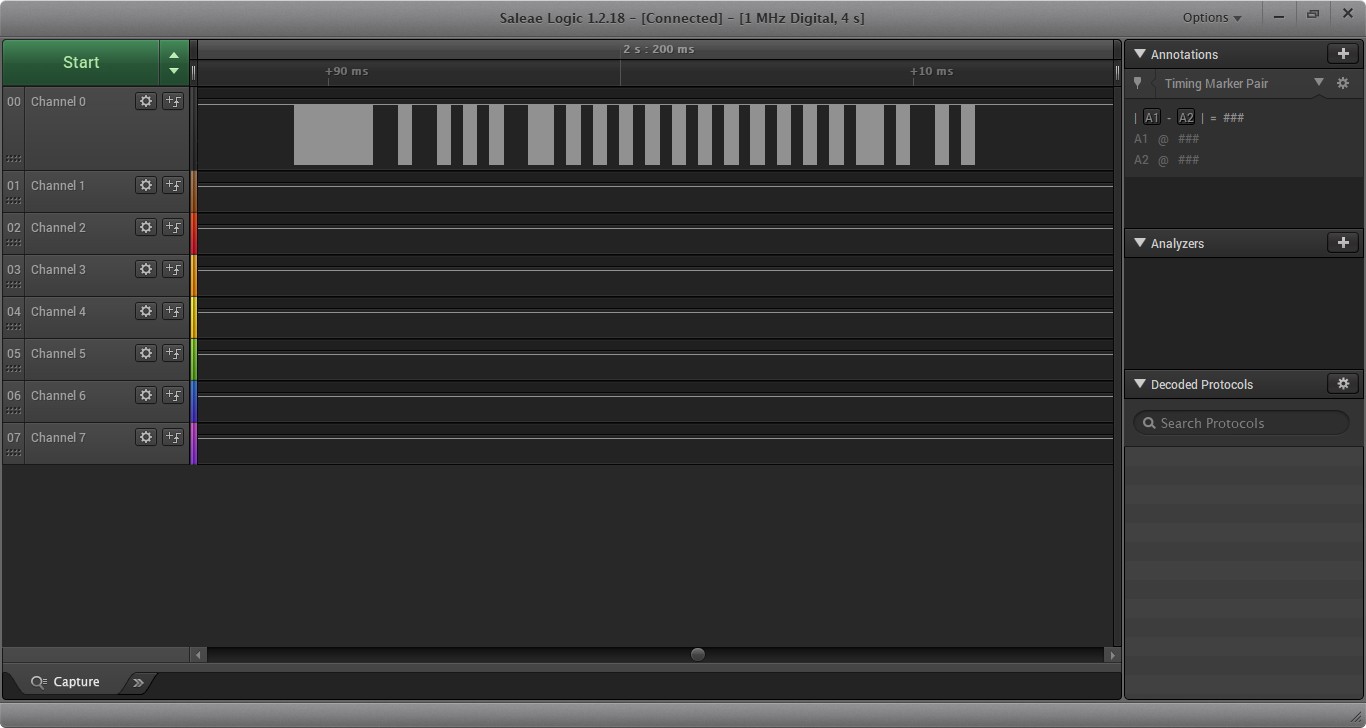
Zoom in, we will see the clear shape of signals. This is the KEY to control TV. Record the period of the peeks.
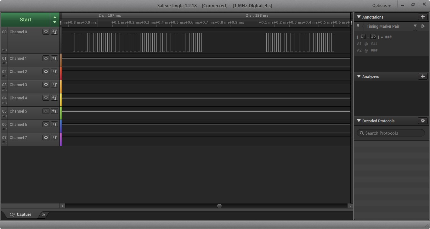
Zoom in more, I will see the signal and get the carrier frequency.
let us chose the IR transmitter and simulate the signal. my reference is https://www.amebaiot.com/en/amebad-arduino-irdevice/
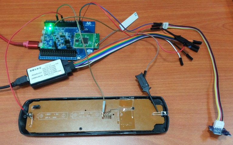
Above are my hardware connections.
Above channel 0 is the real TV signal, channel 1 is my simulated signal. There is no difference if it is active high or low. Because the IR signal is a kind of light, the receiver only gets light or dark. In my case, it is fine.
By https://www.amebaiot.com/en/amebad-arduino-irdevice/, we can simply edit the "irRawSignal" to store all data and let the IR transmitter send them.
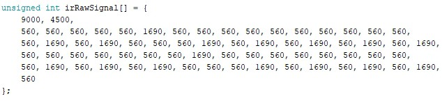
Each pair of the number is a "high peak" and "low peak" of the signal. So if I want to send 5 signals(power on/off, vol +, vol -, ch +, and ch -), there has to be 5 this kind of array. Also, there is 1 more data that needs to be stored, "#define CARRIER_FREQ 38000". the different brand has a different use of IR, which leads to a different frequency.
The next step is to store and read data from a microSD card.
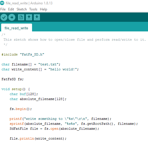
My major codes refer to https://www.amebaiot.com/en/amebad-arduino-audio-fatfssdio/. Basically, I just want to store all data into 5 text files and let the file system help to read from the MicroSD card into the board. Then use all reader data to processed the IR signal.
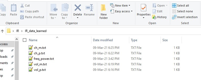
Above are my files, and I have put the "CARRIER_FREQ" stored at the first of the power data file.
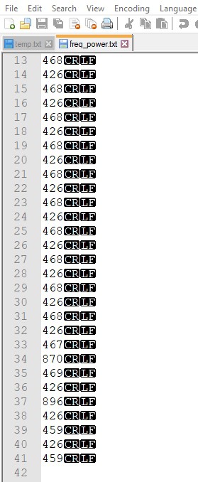
Above is what is inside the file. We should care about "the end of line" ("CRLF"). This considers 1 character when handling the data by referring Ascii Table.
By referring to the above example, it is quite easy to get all data.
In the future, we just need to change or update the 5 files in the SD card, then the system will perfectly match with all brands of TV/IR system.
Now is the real fun part. WiFi webserver part.
Refer to the demo https://www.amebaiot.com/en/amebad-arduino-ameba-web-server/ . it is very easy to make a server, thanks to the example, saved a lot of time.
Next stage, import the HTML for control design.
Well, it should be whatever HTML file I have, I just put it in the SD card and the system should be able to load the HTML design and give me the UI. But I am not able to write an HTML reader by fatfs. So I just hard copy, put each line of my HTML design into the Arduino demo code. just like the demo here, https://www.amebaiot.com/en/amebad-arduino-ameba-web-server/
So we have signal, control, and server. How is the cell phone able to control the system. Or easy to say how does the phone able to find the server? The QR code indeed. ...
Read more »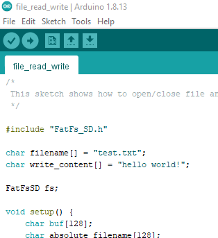


 Debinix
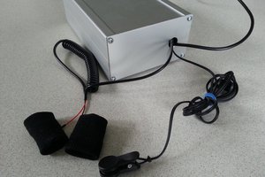
 Andy Castille