Close
0%
0%

Solder Fume Extraction Station Deluxe - from scrap

Inhaling the solder fumes is terrible for the health. Maybe some old parts from my old PCs could supply some details for this project.

Similar projects worth following
It turns out I had a non-functional computer power supply where I had salvaged the chassis and PSU fan. These 12-volt fans are usually both quiet, powerful enough, and reliable.

Initial wish list for my DIY solder fume extractor:

- Use scrap PC parts if possible.
- HEPA and active carbon filter behind the fan.
- Aim for a portable, small tabletop unit.
- Powered by built-in 18650 cells or via USB-C PD wall adapter.
- Open source code and created circuit boards on GitHub.
- Built-in charger for Lithium cells.
- On/Off control by foot pedal.
- Speed control by a potentiometer on the unit.
- Low noise - but you get what you have.
- Use Arduino IDE for code and a cheap microcontroller.
- Maintain a low-cost profile.

Use cases

I initially identified four use cases.

- Truly portable - Run the fume extractor continuously for 8-10 hours with the built-in battery pack before re-charging.

- Wall outlet powered - Run the unit from either a USB power bank or a USB wall adapter.

- Detach the electronic unit, and use it to charge lithium cells - I create multiple uses of the core unit and do not waste unnecessary resources for only a single-use case.

- Use it as a power bank with the built-in microcontroller - Use the detached unit with a microcontroller in other Arduino projects to keep this from becoming scrap.


Project objective

This project will lead us to some new design ideas. Thus, don't expect me to choose the most straightforward solution or use some off-the-shelf ready-made modules. We aim to be semi-professional but still hope this will be an explorative and enjoyable hobby-built fume extractor.

  • 1 × Decommissioned PSU fan PSU 140 mm fan from a Corsair supply, rated for heavy-duty use around 12V@0.7A.

  • POC: Fan PWM control circuit and code

    Debinix01/15/2023 at 16:20 0 comments

    ## Project notes 2023-01-15 (POC: Fan PWM control circuit and code)

    Finally, all POC parts have arrived, Christmas is behind us, and I got some time to continue with the project. I have been distracted by a small Christmas project. The Talking ESP32 Clock is described in detail as an Instructable. Please, have a look and support me in the contest by loving it.;-)

    Initially, I was using the ESP8266 (mainly for cost savings). However, I have gravitated more to an ESP32 as the brain in the project due to its capabilities.
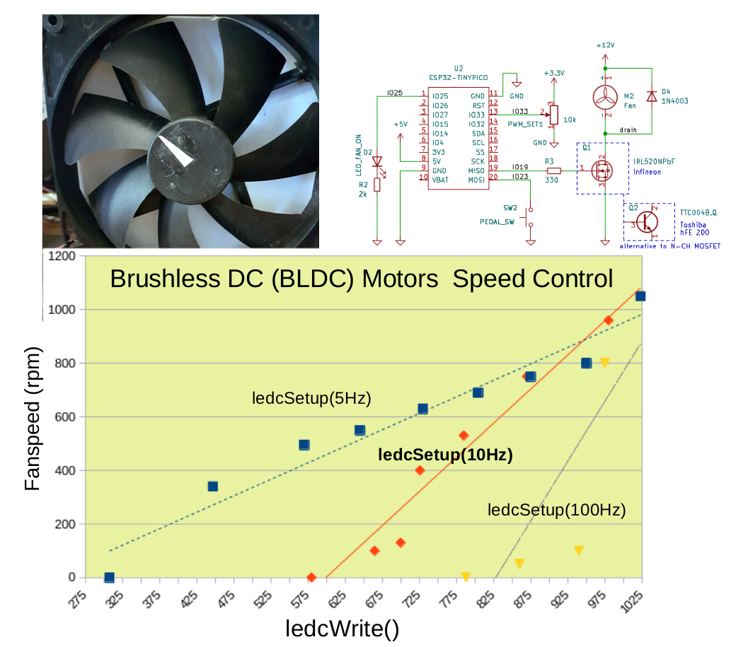
    DC motors are more challenging to control with PWM than fading a LED. One objective is to have a wide range of control over the fan's speed. However, one quickly realizes it is a compromise. Due to the motor's inertia, a high PWM frequency results in a narrow band of control, as shown in the graph.

    Already at 100 Hz, the motor does not respond well when changing the duty cycle. On the other end, i.e., at low frequency, the available control range is increased but at the expense of the fan speed stability. About 10 Hz in the setup PWM methods was a good compromise for this fan. To measure the rotational speed, I used the mobile app RPM Meter - Strobe Light on my Android phone.

    It is preferable to use an n-channel MOSFET (logic level) over an NPN bipolar transistor since it draws less current and has no problems with dissipated power. However, I tried a BJT from Toshiba (TTC04B), and it works equally well, with the only exception of the mentioned slight drawbacks.
    Find the Arduino PWM sketch for the POC on GitHub and the POC PWM schematics.

  • A new Dark Theme for Arduino IDE 1.8.x

    Debinix11/20/2022 at 22:29 0 comments

    ## Project notes 2022-11-20 (A new Dark Theme for Arduino IDE 1.8.x)

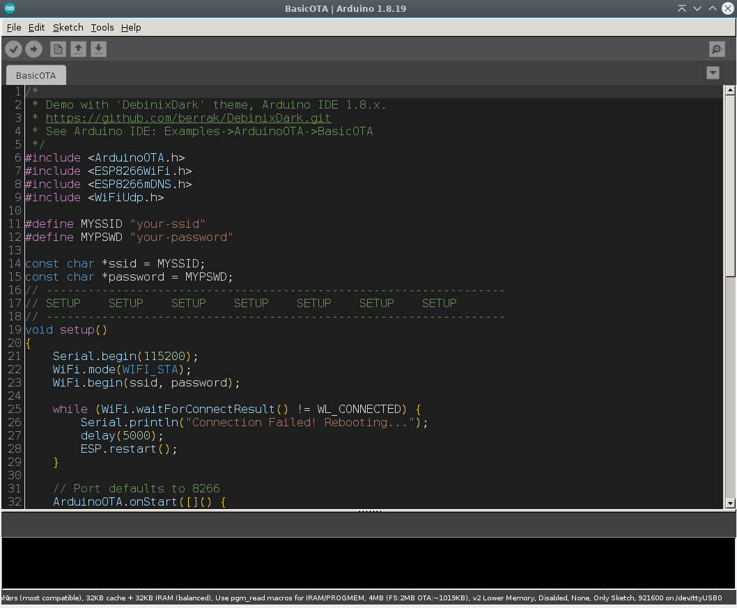
    I'm waiting for some components to tie up loose ends with the initial POC I did a month ago. To save my eyes, I need to do something about the bright theme of Arduino IDE (1.8.x). Now, when I had some free time decided to tackle the problem. A few older dark variants exist, but I was not too fond of their color combinations. 

    The best one was from the end of 2018, by Jeff Thompson. The groundwork looked very promising. I like Visual Studio Code's C++ Dark UI theme and use it as inspiration. All editor element in the Arduino IDE 1.8.x is not customizable, but in the end, I was rather happy after just one day of work. 

    The only primary wish I could not get to work is a better-looking font than the system-appropriate monospaced variant. Try the new DebinixDark theme; it's an effortless install. Enjoy.

  • Elegant OTA updates for ESP8266 and ESP32

    Debinix11/17/2022 at 19:17 0 comments

    ## Project notes 2022-11-17 (Elegant OTA updates for ESP8266 and ESP32)

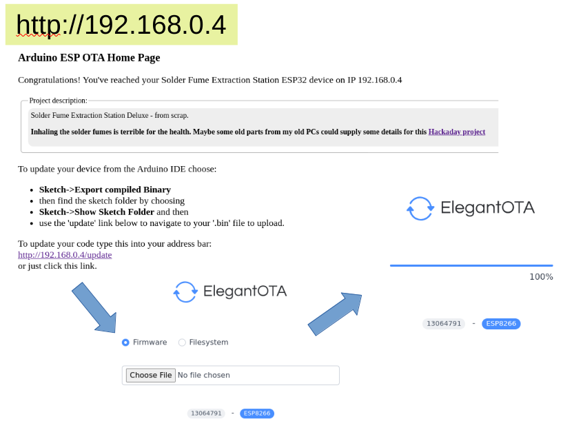
    I reviewed the project's early phases and started drawing a proper POC breadboard-built fan controller schematic. I also verified that OTA updates work flawlessly for the potential microcontroller candidate. Regardless if it will be the ESP32 or the ESP8266.

    There was not much work for me to adapt the code to fit the project. Thanks to the useful Arduino libraries ESPAsyncWebServer, AsyncElegantOTA, and a helpful server landing page by Ralph S Bacon

    The OTA example files are in the Project GitHub extra folder.

  • Telemetry - remote real time ESP8266 data logging

    Debinix11/14/2022 at 16:44 0 comments

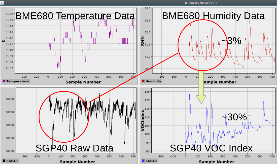
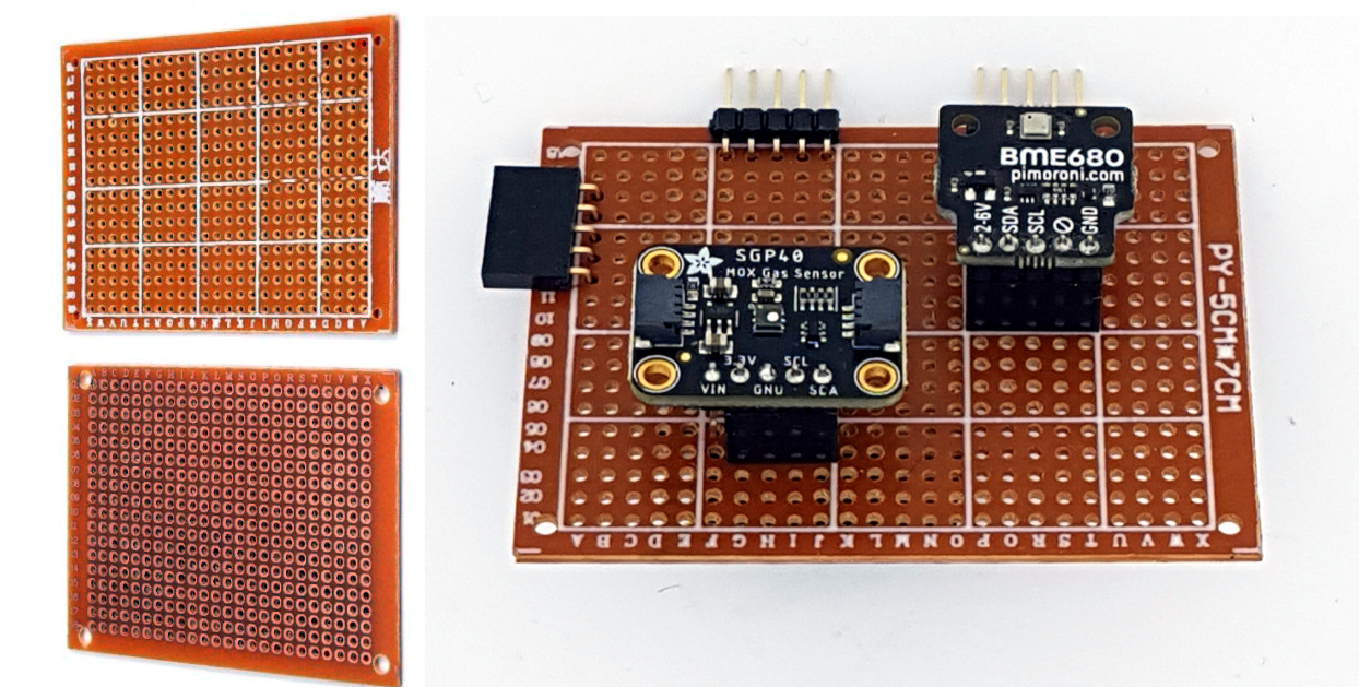
    The air quality sensor SGP40 from Sinsirion and Bosch BME680 temperature, pressure, humidity, and air quality sensor BME680 will be the sniffers for evaluating the fume extractor capabilities to capture nasty solder fume particles. Data is sent as UDP with the ESP8266 via a WiFi access point. The Telemetry Viewer picks up the received packets and plots them in real time. Find the Java-based Telemetry Viewer here. The Arduino code to send a CSV string is straightforward. 

    udp.beginPacketMulticast(broadcast, port, WiFi.localIP());
    udp.write(text);
    udp.endPacket();

    Telemetry adds valuable data insights, which are easy to spot in the graphical visualization of the data. The temperature and humidity are fed to the SGP40 sensor to improve accuracy. Interestingly one quickly realizes that slight noise or variations in the humidity data have a massive effect on the algorithm's VOC index calculations. The same peaks, but inverted, are seen in the SGP40 raw data. I need to investigate more about what is going on here.

  • Larger 1.8" display and working SD-log file

    Debinix11/13/2022 at 15:56 0 comments

    ## Project notes 2022-11-13 (Larger 1.8" display and working SD-log file)

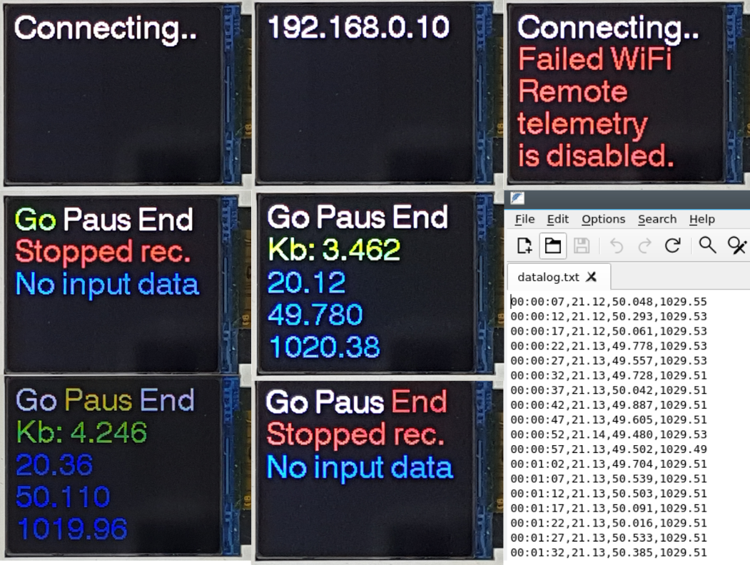
    I promised to look at a slightly larger display a week ago. The larger 1.8" display allows us to add more data on the screen and, in addition, display various non-menu related information. There is a larger display, like the popular 2.8", 320x240 resolution with ILI9341, and with an SD-card slot. It's not unlikely that the final TinyDataLogger will use that in the end. However, for now, 1.8" is beneficial not to add more feature creep in the specification for the project. The intention was to measure and log simple data, such as an analog battery discharge voltage, or use an I2C breakout sensor for air quality experiments.

    There are a few reasons our display will grow with time.

     
    * Configuration: The data sources, calibration, and similar activities. Without a local display menu, it has to be done remotely in a *headless* mode via a web interface, AT commands, or similar. Of course, the WiFi connection has to work for this solution.
    * It's expected that during development, it usually becomes clear that some basic assumptions are not valid anymore. Thus we need the added flexibility.

    Is anything wrong with starting small and gradually maturing the project as we proceed? Unless we require some significant changes, it can be beneficial for two reasons.

    * It tends to reduce the complexity of the prototype stage, and the project does not need to struggle to evaluate way too many scenarios
    * A functional prototype can relatively quickly be realized and thus provide valuable feedback for the continuation of the project.
    As one of the menu displays shows below, I will shortly look into how to accomplish wireless remote data logging, i.e., telemetry.

  • SSD1306 and ST7735 Menu Display

    Debinix11/07/2022 at 20:14 0 comments

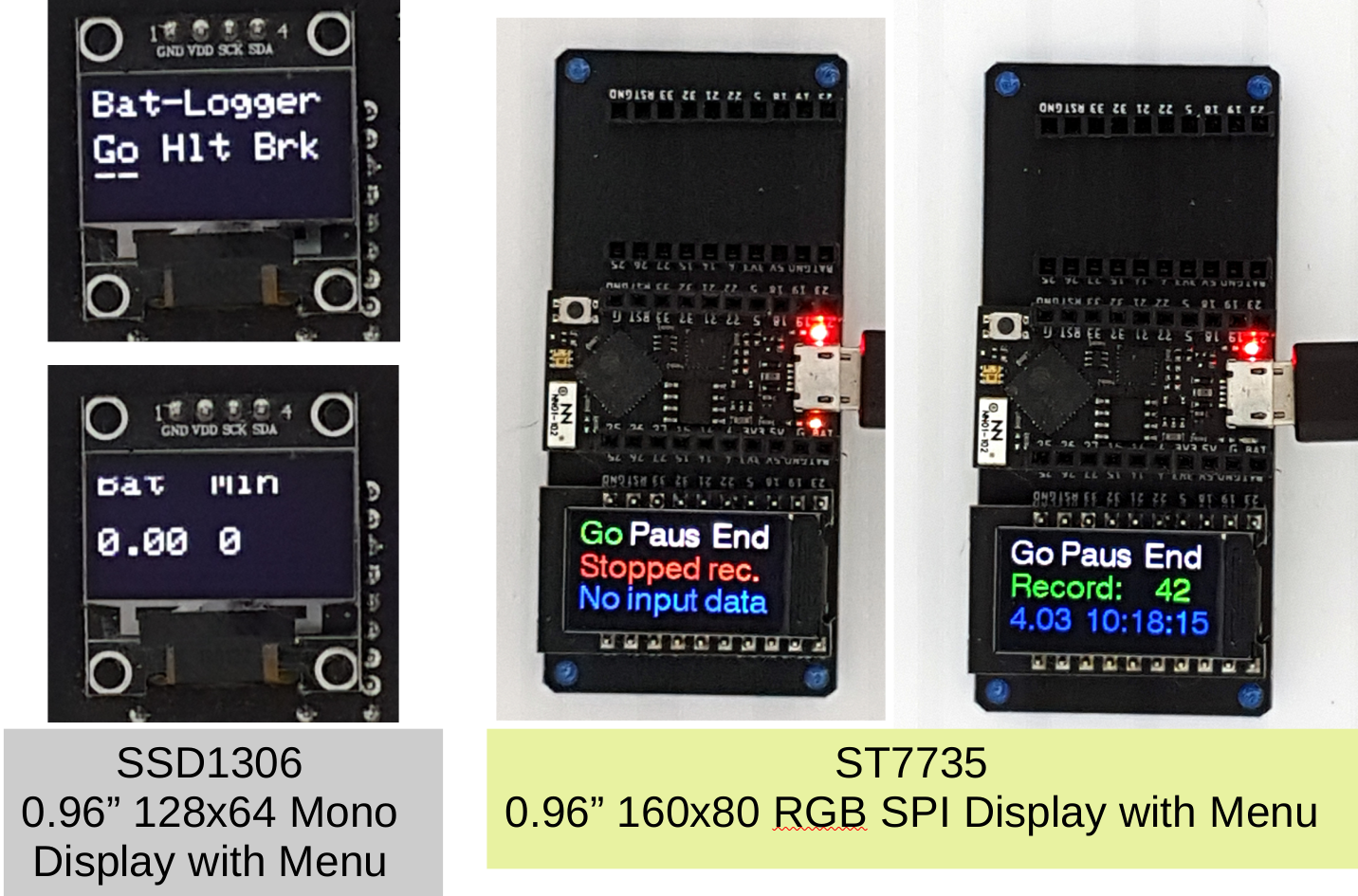
    ## Project notes 2022-11-07 (Mono I2C Display, RGB SPI display, and more)

    I started this project with a very minimalistic approach, one single button to navigate the menu system, and a tiny SSD1306 mono display. I still think the single button will work for this logger, but I decided to look closer at larger displays with new capabilities. This way, the final logger will have some expandability for any new built-in features. 

    The experimental change from I2C-bus to SPI makes DuPont wires a rat nest and unnecessarily degrades signal integrity. The small I2C displays are so forgiving and work almost in every situation. 

    The SPI displays drivers, and the display itself can be pretty picky to get to work nicely together. The preferred Arduino library is Bodmer's TFT_eSPI. There are a few pros and cons to this change.

    * Color display does look better.
    * The menu can use text colors to emphasize the actual state.
    * Less essential to have the RGB (Dotstar) LED to indicate the menu state, although it was great during code development.
    * ST7735 LCD TinyPICO Display will cost more.
    * The current consumption is higher than with the mono SSD1306 display.

    I will look shortly at a slightly larger 1.8" (128x160) OLED display with an integrated SD-card reader. That would be an asset for the logger.

  • Air quality?

    Debinix11/05/2022 at 21:50 0 comments

    ## Project notes 2022-11-05 (Air quality prototyping)

    The development of the code for the logging board has continued. It was fun having the flashing LEDs indicate the actual menu state, which is very useful. Still, it is not practical to tie up so many GPIO ports on the controller for this function.

     However, I was not ready to completely abandon its practical use. I found a better solution using a multicolor, digitally controlled Dotstar diod. I was delighted when the Unexpected Makers ESP32 TinyPICO's had them and included a practical library. Therefore, I have decided to replace the ESP8266 D1-mini with the ESP32 in the project. There are several advantages to doing so.

    - The ADC resolution improves from 10-bits to 12-bits.
    - Numerous ESP32 API functions will help improve the accuracy of the logger.
    - The physical size is smaller with ESP32 TinyPICO. They can be purchased, for example, at Pimoroni and Adafruit.
    - The ESP32 has the memory and speed to add code and new functionality as the project progresses.
    - That may not be true for the initial (too small) display, but we will see. Of course, the project specification still needs to be defined.

    I have to redo the calibration of the new implementation, which is why I'm prototyping. The cost is higher than the ESP8266, but it's worth the extra money. I claim that the solder fume extractor absorbs all the bad stuff; thus, I need to prove it. 

    I have invested in Sinsirion's SGP40 air quality sensor, and I had a BME680 temperature/humidity sensor lying around. The latter sensor will improve the air-quality data. The latest pictured FR-2 prototype board helps generates test measurement data for the SD card.

  • The TinyDataLogger code is born

    Debinix11/02/2022 at 15:06 0 comments

    ## Project notes 2022-11-02 (The TinyDataLogger code is born)

    Finally, the code is slowly coming together for logging battery charge and discharge values. The code consists of the following main function blocks.

    - The menu finite state machine (FSM).
    - NTP-based date/time retrieval.
    - ADC input and calibration.
    - The code that handles the single switch works with short and long presses to control the menu.
    - The I2C display code for either a small 0.96" OLED or a 2x16 LCD. Modify the code to adapt other I2C displays.
    - The SD-writer implementation.

    In the upper half of the FSM is the three choices in the menu, i.e., Start Logging (Go), Paus (Cnt), and Finished (Hlt). The OLED display shows the measured battery value and a time counter in the lower part of the image. 

    I used four color LEDs during the development to get a complementary visual indication for the correct state changes and the usual serial output in the Arduino IDE.


    Implementing and testing the finite state machine for the menu and achieving a robust short/long single switch without bounces consumed most of my time. I will create a separate GitHub repository for the 'TinyDataLogger' since it may have a broader audience interested in trying this out.

  • Logger calibration and code development

    Debinix10/30/2022 at 19:16 0 comments

    ## Project notes 2022-10-30 (Logger calibration and code development)

    The Tiny Logger hack quickly becomes a project on its own. First, the code compensates for the measured offsets between ESP8266 ADC-reading (10-bits) and the measured voltages. Then, the voltage divider factors were applied, and in the end, it came out what you can expect with this level of parts and instrument available to me. A quick summary is as follows:

    - In the low voltage battery range, the relative error is < 1%, except for the very lowest voltages (i.e., 2.5V), which increased to 2.5%.
    - In absolute values, it corresponds to < 30 mV, except for the last point (60mV).
    - The relative error is < 1% at the lower end of the scale and increases almost linearly to ~2% for the high voltage pack case.
    - In absolute values, it corresponds to 50 mV and up to 200 mV at the highest voltages.

    One has to be satisfied with the results, considering these inexpensive parts, the short time spent, and not digging deeper into these inaccuracies.
    For the code itself, I'm adding a tiny menu to be able to start, halt, and break the logging to the SD card. What remains is to add date- time stamps to the log and to complete the SD-write part. A GitHub repository is halfway ready to go public with all coming fume extractor code, including various utilities - thus, this is what I will do in the coming days.

  • Build a battery voltage logger

    Debinix10/28/2022 at 20:17 0 comments

    ## Project notes 2022-10-28 (Build a voltage logger!)

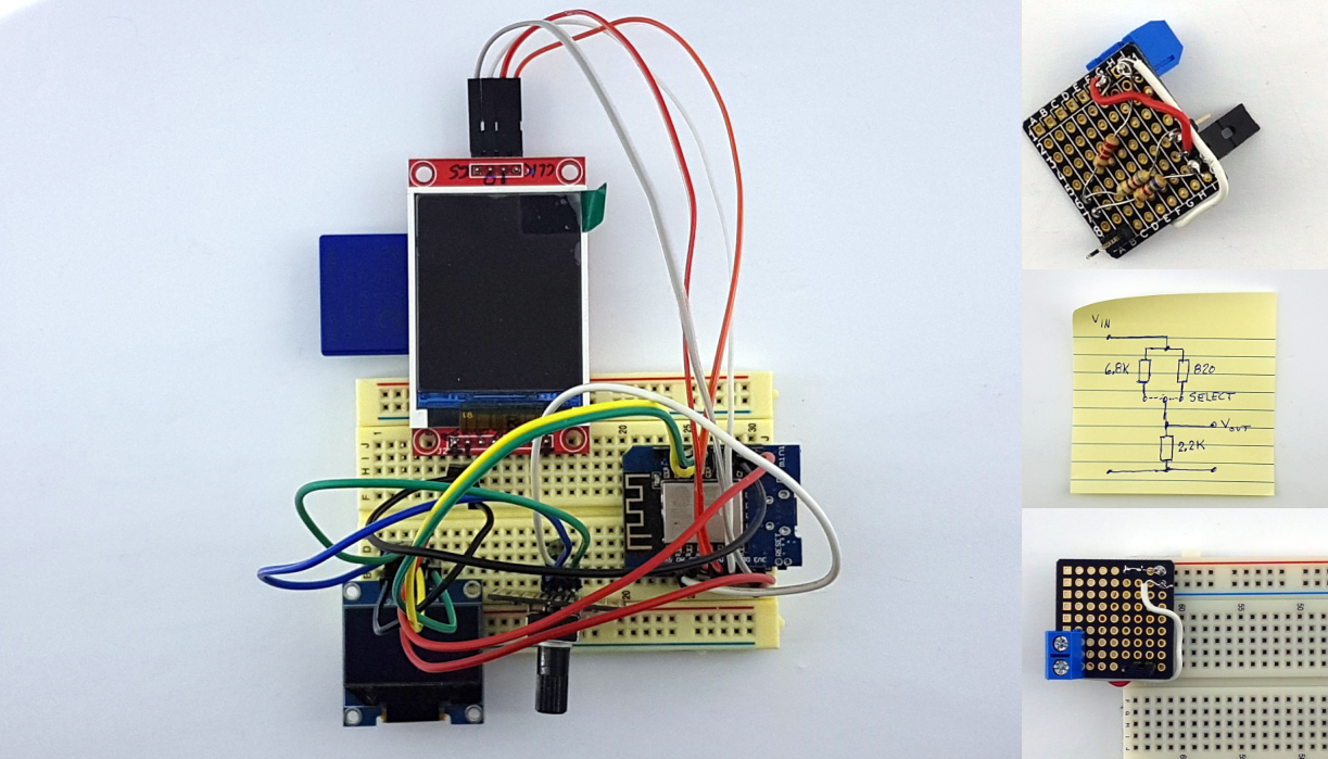
    I need a data logger to track charge- and discharge characteristics during the project, and I just realized I don't own one. So let's build one quickly and write some code in Arduino IDE. We need these parts:

    - ESP8266 D1-mini to read the analog voltage (DAC) and be the brain of the breadboard logger.
    - SD card reader. Many SPI displays have these as standard. I found that I had one, but only with the old large SD card format.
    - I need some display to monitor the logger process.

    3S-lithium is commonly charged up to 12.6V (3 x 4.2V) and the microcontroller ADC only handles up to 3.3V. For cells in parallel, the maximum voltage is 4.2V, and this is not optimal for the ADC available 10-bits. So the simple voltage divider was rapidly born. With a jumper, it can reduce the input voltage to either 75% or 25%. That should cover our needs. Purchase these small and very useful mini-boards at Tindie if you are curious.

    I will soon set up a GitHub software repository for the project and all other helper programs that may be added, like this logger code.

View all 13 project logs

Enjoy this project?

Share

Discussions

Similar Projects

Does this project spark your interest?

Become a member to follow this project and never miss any updates