Close
0%
0%

Tachycardio

An arcade heartrate racing game

Public Chat
Similar projects worth following
As I only have the chassis for this project at the moment, and it is my only experience using CAD for 3D printing, I would love any and all feedback on it!

An interactive artwork for an exhibit scheduled to happen in the next year:
Your circulatory system is one with the pupabot, and so is everyone else's. Each beat of your heart is supplying it with the oxygen it needs to get ahead of the rest. Jump around, give yourself anxiety, do a line- whatever it takes.

license: CC Attribution to Yulia Skorina


Premise

'Tachycardio' is a larger-scale, higher fidelity iteration of a previous biometric robot project 'Two products of a heartbeat'. The handmade chassis of 'Two Products' limited its walking ability. With biometric capabilities out of the way, 'Tachycardio' is an exercise in the articulation of a robot. 

Purpose

Tachycardio is being developed for a show by Elektrolab in Brisbane due to be completed sometime before September. The show is conceptualised as an ecclectic arcade, Tachycardio being placed among other interactive art pieces. 

Concept

Users race a crawling, wiggling pupa-larva-robot with their heart rates across a surface. There is a random chance that a large, crab-like robot controlled by all the player's heart beats emerges mid-game sweeping the racing surface. The game temporarily switches to a cooperative mode as the players have to attempt to align their heart beats. 

The concept is very similar to my previous project in that the goal is to ask the audience to identify with their heart beat as a life giving process they have little direct control over, and subsequently highlighting our dependence on the biological and the subconscious. In Tachycardio, asking the user to attempt to control their heart rate, accelerating it potentially to an uncomfortable extent, makes them super aware of their heart and its limitations, perhaps at the cost of emphasis on the subconscious. 

I'm hoping a competitive/cooperative premise will engage the audience more. The power of visualising biometrics is demonstrated throughout interactive art. 
Sean Montgomery uses interactive biometrics frequently in projects such as Hivemind (that explores subconscious communication of brainwaves between individuals) and Emergence (which creates a visual link between electronics and the biological body).
The power of organic machines in a fine art setting is demonstrated in the portfolio of Michael Candy, who anthropomorphises and mystifies robots. See: Little sunfish, Cryptid, Azimuth.

Robot: Pupabot

Design

Aesthetic

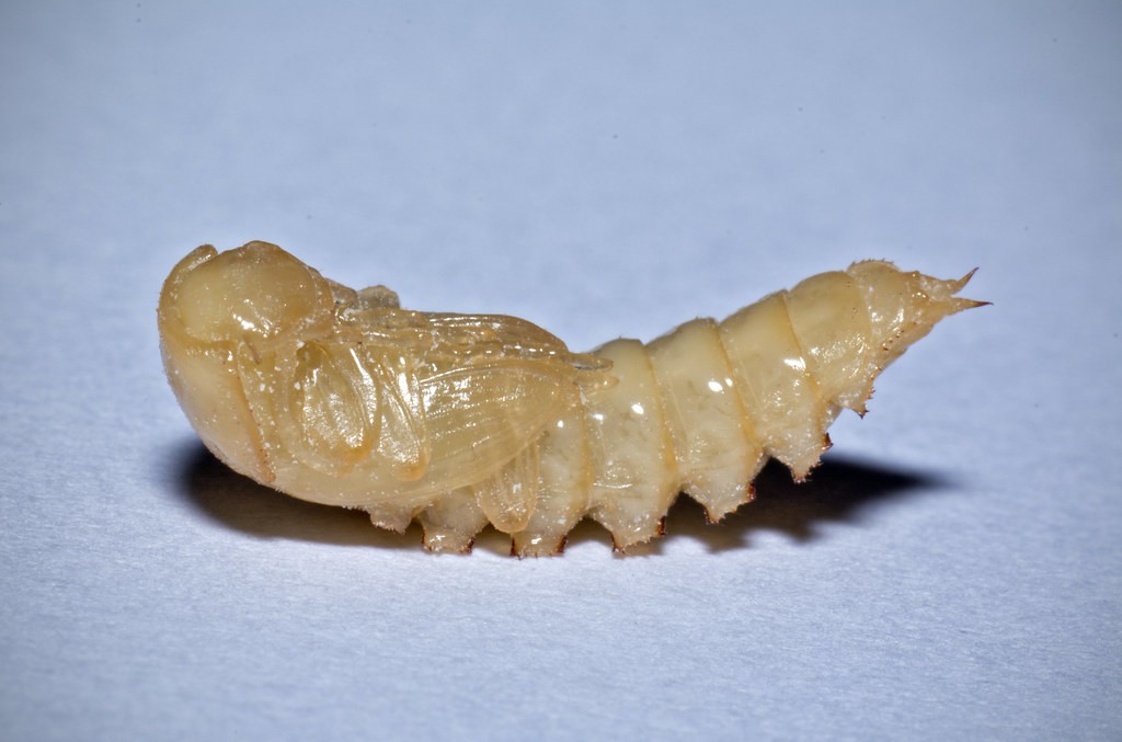
The robot combines some features of sea fleas / mole crabs and a darkling beetle pupa which I've handled lots through my mealworm farming adventures. The tail will be covered in sand-coloured suede and the eyes will glow bright white. 


Technical

The gait of the robot is inspired by Slant Concepts' Crawling Robot,  After investigating a dozen modes of robot locomotion, I chose this gait because it is simple and stable while still being dynamic and organic. Other gaits rely on a considered centre of mass or were not sufficiently dynamic.  The arms of the Pupabot are inspired by hexapod designs, but specifically I looked to Jason Leung's Quadraped Robot

The print-in-place tail is inspired by the many flexi-toy designs on Thingiverse.com, such as this lizard.

Fabrication

Cad

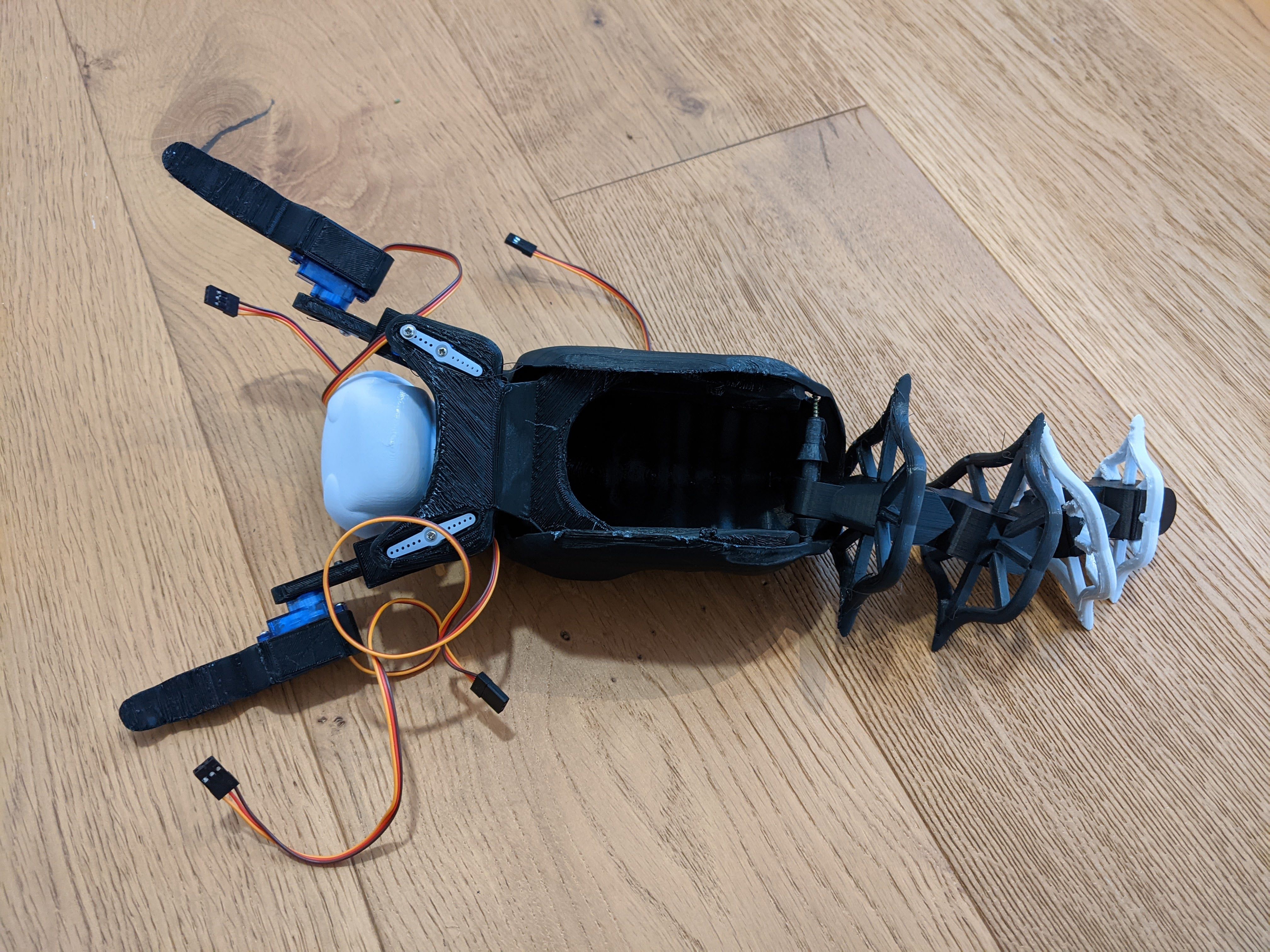
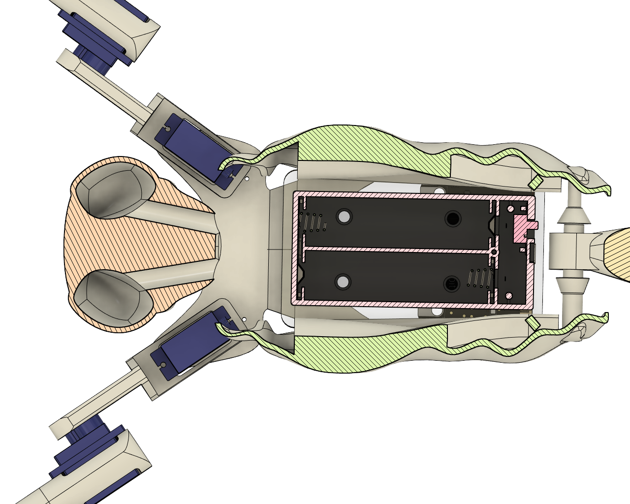
The shell houses two acrylic plates supporting the power supply and Microbit. The plates sit on rails and are stopped at the end. I suspect after prototyping I might have to pitch the tails down toward the stoppers, but the shell might also be in a tilted position due to the gait anyway, 
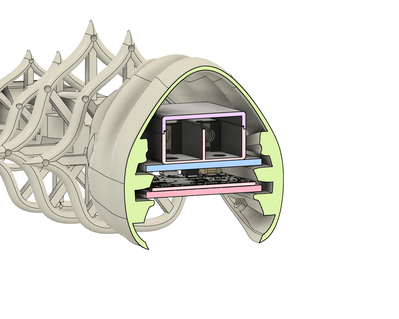
Another view of the shell cavity.
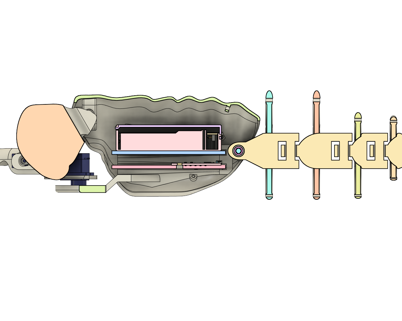
7.5mm tunnels for 5mm LEDS to be inserted into the eyes from the inside. The eyes are a thin-walled cavity so that they pass through but diffuse light while the head is solid (depending on infill). 
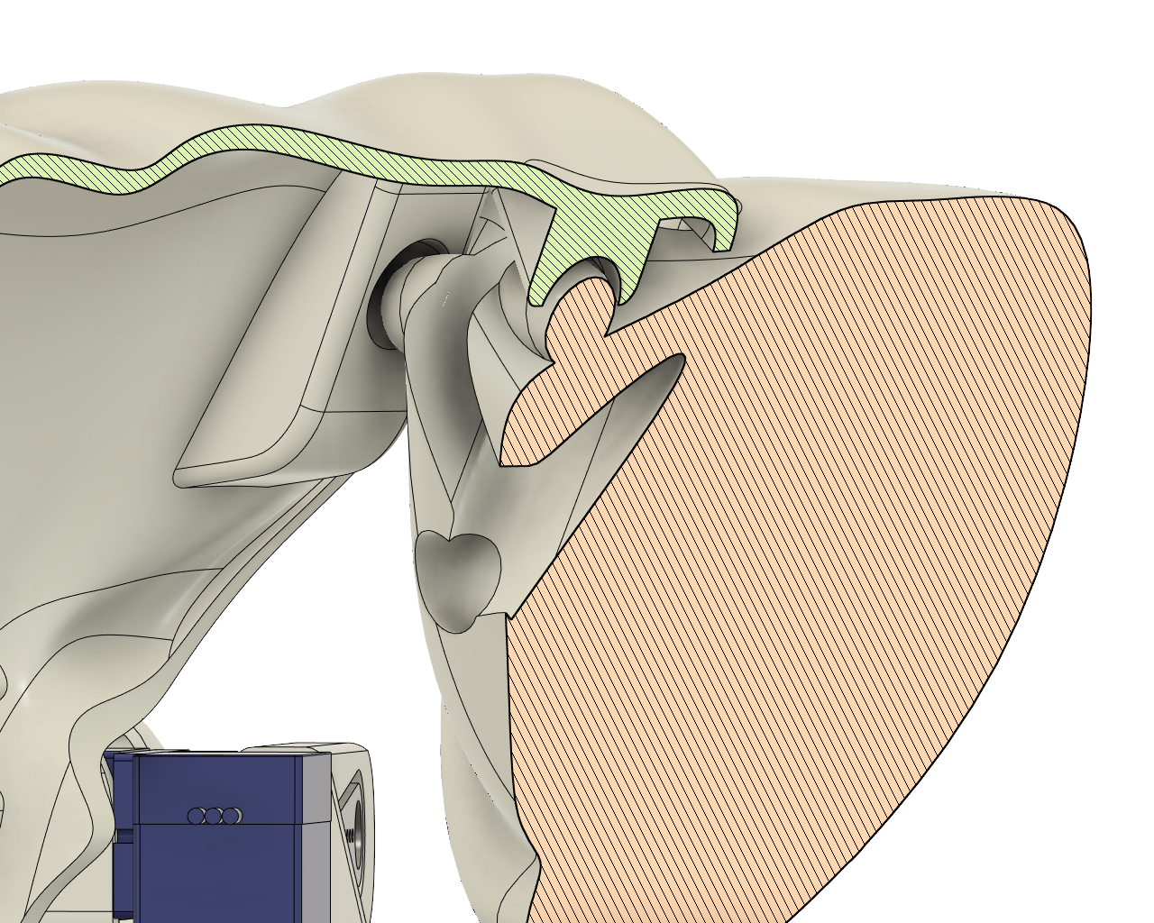
The head is held in place by (hopefully) flexible prongs that compress with a pinch.
The Print-in-place tail chain is attached to the shell via a separately printed axel. It took extra time to figure this one out and I am not entirely sure that it will work. I will have to find out through physical prototyping. 

First the inside components of the axil are inserted into the hole of the tail chain. Then caps are inserted into the inside components of the axil through the outside. 
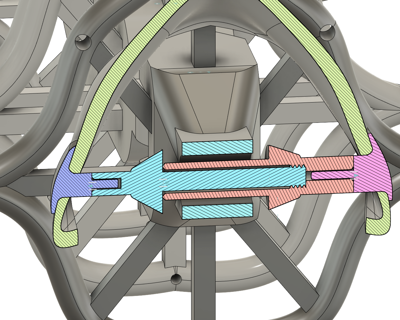
Comes apart like this:...

Read more »

Pupabot_Chassis_Assembled.stl

Standard Tesselated Geometry - 18.76 MB - 04/21/2021 at 12:39

Download

Pupabot_Chassis_Seperate1.stl

Part 1/2 The gcode for this one was too big Infill 15%, 2mm layer height, 65% overhang tree supports touching build plate, everything else default CURA settings for UM2+

Standard Tesselated Geometry - 7.04 MB - 04/21/2021 at 12:38

Download

Pupabot_Chassis_Seperate2.stl

Part 2/2

Standard Tesselated Geometry - 2.82 MB - 04/21/2021 at 12:38

Download

UM2_Pupabot_Chassis_Seperate2.gcode

Part 2/2 The gcode for part 1/2 was too big, see STL description. For um2+

gcode - 22.28 MB - 04/21/2021 at 12:39

Download

pupabot_acrylicplates_3mm.ai

postscript - 319.94 kB - 04/21/2021 at 12:38

Download

  • 2 × BBC Micro:bit All other processors would definitely do a better job
  • 4 × 9g stepper microservo motor
  • 1 × Pulse sensor
  • 2 × 5mm led of choice
  • 1 × PLA chassis

  • First and Second draft print

    meatqueen08/30/2021 at 09:59 0 comments

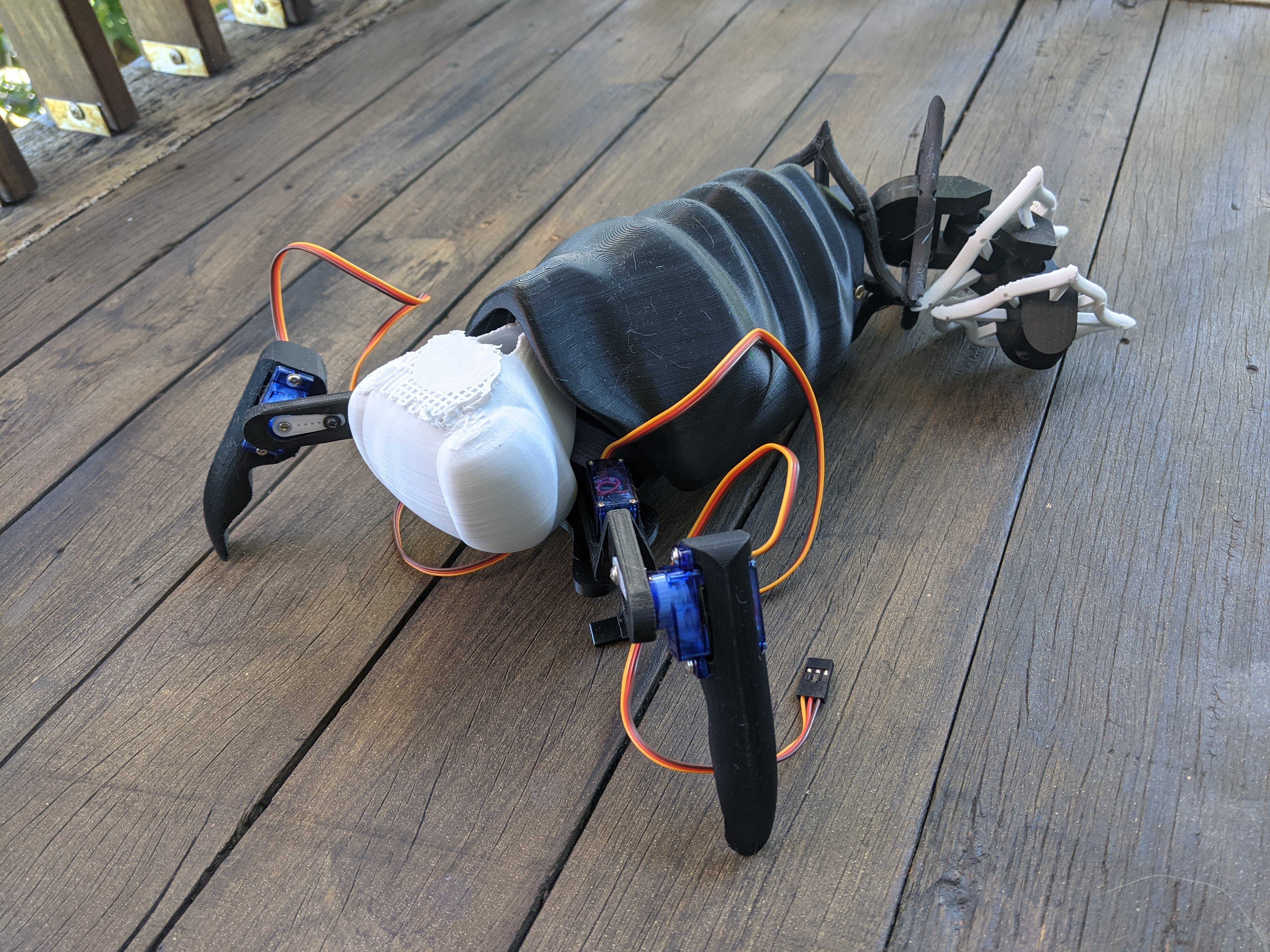
    First draft in black. Some issues:

    • The head fittings were too round and slipped easily out of the sockets.
    • The servo arm holes printed poorly and filled in.
    • The last two tail frames were not probooleaned correctly and did not fit over the vertebrae.
    • The tail screw covers were too fine and snapped. 

    In the second draft (white), they were adjusted:

    • The head fittings are now cones rather than hemispheres, and are futher apart so that the pressure that's keeping them in there is higher. This helped, but now it is a bit tight. I will continue to iterate. 
    • The walls of the eyes were thinned to allow more light through them, but PLA is still pretty opaque. I will have to do a test with internal LEDs. They are at minimum thickness at this stage and if they are still opaque, I will consider removing them altogether and sculpting them out of thermoplastic instead which is semi-transluscent. 
    • The tail frames were cut correctly and now fit over the tail. 

    The third draft (yet to print), has had these changes:

    • The recesses for the servo arms have been made deeper.
    • The tail screw caps are thicker and longer
    • the cavity of the head fitting is now set deeper and is more concave to allow the fittings to move more freely within the cavity, but not fall out. 

    When my model is completely functional I will post a new file. 

View project log

  • 1
    Printing the Chassis

    Both STL files are sized for an Ultimaker 2+

    pupabot_seperated_part1.stl is large, I will try to print it with 2mm layer height, 15% infill and 65% overhang tree supports. All other settings are default Cura settings. 
    pupabot_seperated_part1.stl is smaller, 1mm layer height, 20% infill and 50% overhang tree supports. All other settings default. 

    pupabot_assembled.stl is simply for illustrative purposes and should not be printed. 

  • 2
    Putting together the Chassis

    As I haven't yet printed the model, a demonstration of how it comes apart and is put together is above. When I print it and finalise the model I will also attach photos. 

    1. The tail frames and the tail chain are printed separately to make printing more efficient. Slide the frames onto the chain and glue them on. Integrity is not super important for the tail. 
    2. Fitting the axel in the tail is a 2-step process: first fit one half of the axel through the end vertebrae, screw the other half of the axel on. Then line up the fitted axel and end vert with the inside of the holes in the chassis. Slide the axel caps into the chassis holes from the outside, into the axel. The larger axel half fits the cylindrical cap and the smaller axel half fits the prism cap. 
    3. Fit a suede cone over the tail and attach the fabric to the frames by threading a needle through the holes along the perimeter of the tail
    4. Tie the ends of the suede cone to the loops on the inside of the shell. 
    5. Insert LEDs and wire into the eye holes in the back of the head piece. 
    6. The acrylic plates supporting the battery and the microbit (and all of the connections) should be inserted before connecting the head.
    7. The head needs a bit of a squeeze to take out/put in. The flatter surface is 'Up' so it is printed upside down. 
    8. The legs are held together by servos. The second joint should be assembled first, fitting the claw behind the servo body screws. The servo should be facing the inside of the body. Fit the forearm piece over the servo head with the side that has a gap for the shorter servo arm. Fit servo arm over it and screw it on. Once again it should be facing the centre-line of the body. 
    9. Fit the second servo into the other side of the forearm piece. The screws should be facing upwards. The arm piece should be fitted behind the servo. Then fit the second servo head through the hole in the shell, screwing a double servo arm on the other side once again. 
    10. Repeat on other side. 

View all instructions

Enjoy this project?

Share

Discussions

falvernook wrote 05/31/2023 at 11:10 point

There has been a great deal of value to me in my involvement with the project. Would like to share it with the Tierbestattung Balingen team so they can also read it and implement something new.

  Are you sure? yes | no

Dave wrote 04/28/2021 at 10:41 point

This is hilarious - I love the concept. As a clinician, I'm wary of commercial "biofeedback" devices because they are all designed to only train my clients to better activate parasympathetic tone. That's only one side of the coin: the goal is not to be never be stressed, it's to be appropriately sympathetic at the right time. I guess medical device companies, and other clinicians, are wary of devices teaching people how to amp themselves up because it's a personal judgement call as to whether or not you're appropriate stressed for a given situation. Athletes and coaches describe this as the inverse-U arousal curve, but IDK if they use any devices to actually calibrate sympathetic stimulation.  Either way, this looks like it would be a laugh.

  Are you sure? yes | no

meatqueen wrote 05/17/2021 at 07:44 point

Hello Dave! Thanks for your interest :).
Oh yes I've heard of this! I am aware that there are ways to measure sympathetic and parasympathetic tones. A friend of mine showed me some expensive bit of software that can discern it from just a pulse sensor and he uses it to support his hypnotherapy. 

  Are you sure? yes | no

Dave wrote 05/19/2021 at 21:23 point

That is cool. Love it

  Are you sure? yes | no

Dejan Ristic wrote 04/21/2021 at 15:03 point

Nice creepy crawly! That's some intricate CAD-work. Will the tail be motorized as well? Or just the claws?

  Are you sure? yes | no

meatqueen wrote 04/22/2021 at 01:21 point

Thanks Dejan!
I thought about motorozing the tail too, but decided against it due to the limitations of the Micro:bit. For the moment it waggles due to the gait. In the future when I use a more powerful microprocessor, I can see how it could be motorized with a pulley thread running through the thread holes along the tail, connected to a servo. 

  Are you sure? yes | no

Similar Projects

Does this project spark your interest?

Become a member to follow this project and never miss any updates