Close
0%
0%

Volumetric Display using Acoustically Trapped Ball

This project uses a phased arrray of ultrasonic transducers to levitate and move a 1mm foam ball to draw in mid-air using the POV effect.

Similar projects worth following
This project is built around "Rethink Displays" - it's a real 3D image floating in mid-air! It doesn't require the user to wear any special glasses and it's full color viewable from any angle.

By using phased arrays of ultrasonic transducers, it is possible to levitate a small 1mm foam ball and move it around at speeds greater than 1m/s. By moving the ball very quickly and leveraging the persistance of vision effect (with a 10Hz update rate), this project can draw images in mid-air in a volume of 100x100x140mm. RGB LEDs are used to illuminate the foam ball at various points in its path to create multi-color images. 4 FPGAs are used to convert a position into the phased signals needed to drive the transducers. The FPGA can also rotate, translate and scale the images. You can even create animations (e.g. an animation of a butterfly flapping its wings.) Kicad schematics and PCB layouts, FPGA code and simulator code are provided as well.

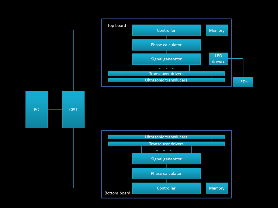
This project shows that it is possible to create floating 3D images.  Imagine being able to see life-sized (albeit small) models of the item you were buying or a CAD model you were building, or even possibly the face of a loved one in full color 3D, without the need for cumbersome glasses creating simulated 3D glasses.  This technology also allows a user to feel objects with their fingers and to hear sound localized to parts of the image - so not only can you see the face of a loved one, you could also touch and hear them.

All the build files, including source code, schematic and layout files and FPGA code can be found here: https://github.com/danfoisy/vdatp

This project is based on a Nature Journal paper: http://sro.sussex.ac.uk/id/eprint/86930/  

Licences:

Qt: LGPLv3 

KiCad: GNU General Public License version 3

KiCad Libraries: CC-BY-SA 4.0

Quartus 18.1 Lite: proprietary Intel license

  • The design

    Dan Foisy06/09/2021 at 00:47 0 comments

    The design consists of 2 identical boards, each with 100 transducers. 

     Each board also has a controller and memory, and something to calculate and generate the phase signals for each transducer.  A Raspberry Pi is used to control the two boards. The transducers I sourced are 10mm in diameter and rated to 40V.  To drive each transducer, I used a MOSFET driver configured as a full H-bridge to essentially double the power the university group had used, figuring that I’d be able to move the bead that much faster (which actually turned out not to be the case). To generate the transducer signals, I decided to use an FPGA.  This was partly because I needed a lot of I/O pins – more than 100 on each board – and also because I wanted to be able to calculate and change the individual signal phases at a rate of 40kHz, something that seemed to be a stretch to do on a micro.  I had hoped to find an FPGA in a TQFP package with enough I/O and gates to be able to run all 100 transducers on each board but such a thing didn’t exist.  It was simpler just to stick 2 FPGAs on each board and have them each run 50 transducers.I also added EEPROMs for each FPGA to store images.

    On one of the boards, I put a Raspberry Pi W as the main controller.  The PI sends SPI commands to all the FPGAs simultaneously.  To keep the FPGAs synchronized, one of the FPGAs generates a 40kHz synchronization pulse that all the other FPGAs listen to.  Because I was a little paranoid about all the EMI I might be generating, I decided to use RS485 differential signalling to send the SPI and sync signals from one board to the other.

    To illuminate the foam ball, I use 4 3W RGB LEDs at each corner of the ultrasonic array.  Each color is driven by dedicated LED drivers – the drivers can be PWMed to change the relative brightness of each color.

    Lastly, there are 4 DC/DC converters – one to step the 24V input voltage down to drive the transducers, two separate 3V and 1.2V converters to drive the FPGA and associated logic, and one 5V converter to power the Pi

  • The simulator

    Dan Foisy06/09/2021 at 00:41 0 comments

    Once I had a rough handle on the physics, I built a simulation of the system to see if it was even possible to do what I wanted.  The simulator calculates the phases for each of the transducers and then determines the pressure wave magnitude for every voxel in the 3D volume – each voxel in this case is 1mm^3 and the total simulation volume is 100x100x145 mm. 

    Since the calculation of the pressure wave involves calculating and summing the signals from each of the 200 transducers, it would take many seconds to run the math on the CPU.  To make the process a little less aggravating, I dusted off my CUDA skills and wrote some GPU kernals to do the math – this is such a highly parallel problem, the GPU is able to process all the math in under 10ms.   I then learned enough OpenGL to be able to draw the voxels on the screen fast enough to get some decent animations.  I probably would have been able to do all the math in an OpenGL vertex shader fragment rather than using both CUDA and OpenGL – live and learn.

    The simulator also helped me figure out how to move the particle along a pre-programmed path.  Initially I thought it would be faster for the particle to never slow down and so I made each right angle corner slightly rounded but it turned out to be faster to bring the particle to a stop at each right angle and then change direction. If the shape didn’t have angles greater than 90 degrees, it probably would be faster to never stop it.


    Here I’m showing how the resulting waveforms interact with each other for two 10x10 arrays of transducers – the focus point is in the middle of the volume. You can see how the waves reinforce each other and create standing waves where a ball object might sit. You can also see that there’s not one single of high pressure but a series of them stacked on top of each, about 2mm apart.  However, the further you get from the focus area, the weaker the high pressure area is.

    This simulation looked about right to me – it showed all the standing waves as expected and it showed that it was possible to calculate the phases of the transducers to focus the sound and that it was possible to move the focus point.  With that validation I decided to build this thing

  • The How

    Dan Foisy06/09/2021 at 00:34 0 comments

    The first step to building this was to figure out how it worked – the paper was a great help here.  Each transducer needed to be fed a 40kHz wave form – but with a phase relative to the other transducers calculated to ensure that the high pressure areas converged at a specific point in 3D space.  Moreover, the signals from the downward-firing transducers had to be 180 degrees out of phase with the ones firing upwards.  

    The original Nature paper lists a formula that allows the calculation of the phase delay φT for each transducer given a focus point p:

    Where N represents the number of discrete phases, k the wave number (k=2 pi/ lambda), pt represents the position of the transducer and the function d calculates the Euclidean distance.  The function takes the focus point as an argument and for each transducer, calculates the distance from the focus point to the transducer, multiplies that by the so-called “wave-number” that converts the distance into a phase and then limits the resulting phase to an integer number from 0 to N-1.  Modulo adding N/2 to the result gives the phase for the downward firing transducers.

  • The Why

    Dan Foisy06/09/2021 at 00:14 0 comments

    About 5 years ago, I showed one of my kids a clip by Physics Girl (awesome channel BTW) of an ultrasonic levitator:

    He immediately wanted to build one so we bought the kit and we spent most of an afternoon  soldering it together.  He was pretty proud of himself and he decided to make a science fair project on Sound – he even went to the local science fair!   I highly recommend you watch the Physics Girl clip as she gives a great explanation of how it works but essentially there are two opposing sets of ultrasonic transducers emitting waves of 40 kHz ultrasound 180 degrees out of phase with each other.  That creates standing waves of low and high pressure where a light object can hang out.  The bowl shapes that the transducers sit in helps focus the sound.

    Fast forward about 4 years; I ran across an interesting paper in the journal Nature of a group at the university of Sussex who took this concept further, way further.  Essentially, they used a phased array of ultrasonic transducers to move a Styrofoam ball through the air so quickly, they were able to draw floating images in mid-air!   http://sro.sussex.ac.uk/id/eprint/86930/

    Of course, I had to build one!  What was even cooler was that not only was it possible to display 3D images, it was possible to also modulate the ultrasonic waves in such a way that you could feel the waves focused in 3D space - a 3D haptic device!  And you could further modulate the ultrasonic signals to interfere with each other in such a way that they could produce sound in the human audio range!  A display, a haptic device and a speaker, oh my!

View all 4 project logs

Enjoy this project?

Share

Discussions

Bart wrote 11/15/2021 at 12:02 point

Wow what a gem of a project, really amazing work!

  Are you sure? yes | no

metalbug wrote 07/03/2021 at 10:46 point

woow this is the prototype of a holographic display

  Are you sure? yes | no

Dan Foisy wrote 07/03/2021 at 14:30 point

thx!  not sure physics will let this go much further but who knows? 

  Are you sure? yes | no

alexwhittemore wrote 07/03/2021 at 00:51 point

absolutely colossal work! I’ve built this exact array twice for two different companies, and your simulation and onboard waveform calculation work in many ways outstrips either. 

  Are you sure? yes | no

Dan Foisy wrote 07/03/2021 at 14:31 point

oh cool - would love to hear more about the applications you built this for!

  Are you sure? yes | no

alexwhittemore wrote 07/03/2021 at 16:08 point

At uBeam, we built an array with basically the same topology (albeit much higher element count and power, using custom transducers for higher density). At Emerge, we built NEARLY the same array for projected haptic feedback (based around a Max10 instead of a cyclone).

  Are you sure? yes | no

Dan Foisy wrote 07/03/2021 at 20:22 point

Both applications sound awesome.  I've played around a little with haptics with the arrays I have and it's so surprising (to me at least) that there is a physical sensation.  I get a number of audible harmonics in my system, wonder if that might be a limiting factor in commercial applications.

  Are you sure? yes | no

alexwhittemore wrote 07/03/2021 at 20:42 point

I agree, it's a very odd sensation! Another cool sensation when you do have those audible elements is hearing the sound reflect off the back wall of the room, then blocking the focal point with your hand and hearing it disappear. Then moving your hand around, and hearing it disappear as the focal point aligns on the gaps between your fingers, and projects through unimpeded. 

The audible elements are mostly from modulating phase too rapidly without slewing. If you change a given element from 90* relative phase to 270 instantly, for example, the physical element can only react so fast and you get some mixing or something like that you can actually hear. The higher Q factor the device, the worse the issue. I bet you don't hear much noise when all the elements are in steady state, right?

  Are you sure? yes | no

Dan Foisy wrote 07/04/2021 at 00:46 point

I definitely can hear it when the focus point is changing - a circle sounds circular :) But there is definitely a high pitch whine that is present when both arrays are on and pointing at each other.  I would have to double-check if it's there when only one array is on and there aren't any close reflectors.  I suspect the number of ceramic caps on the board isn't helping either.

Have to try some more sound projection experiments!

  Are you sure? yes | no

alexwhittemore wrote 07/04/2021 at 00:59 point

Oh that's an interesting point, I hadn't thought about the opposing array, which may be contributing. Also, if you pump enough power density into a focal point, you can actually exceed the air's capacity for sound and cause nonlinearity that might create audible artifacts. I.e. if the sound amplitude is in excess of 14.7PSI, the negative stroke will clip at vacuum. That's like 194dB SPL though, and I'm not confident your arrays are actually big enough or focused enough to hit it. 

  Are you sure? yes | no

Dan Foisy wrote 07/05/2021 at 00:13 point

good to know!

  Are you sure? yes | no

peter jansen wrote 06/28/2021 at 18:47 point

This is awesome work!

  Are you sure? yes | no

Jan wrote 06/29/2021 at 09:32 point

+1!

  Are you sure? yes | no

Dan Foisy wrote 07/03/2021 at 14:31 point

thx!

  Are you sure? yes | no

Similar Projects

Does this project spark your interest?

Become a member to follow this project and never miss any updates