 RetroModder
Available in kits on Tindie | Etsy
Available pre-assembled on Tindie | Etsy
Link to Assembly Manual
Link to Compatible Motherboards
The GameCubePC can be built using either an mSTX form-factor motherboard or an Intel NUC7.
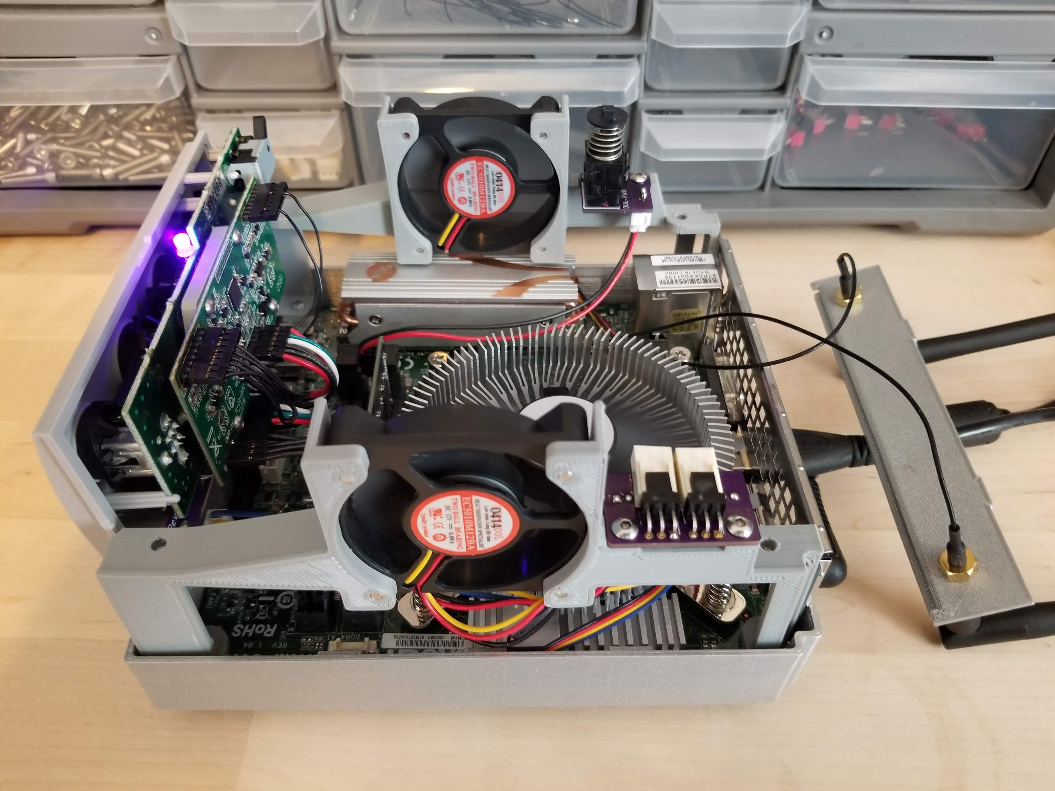
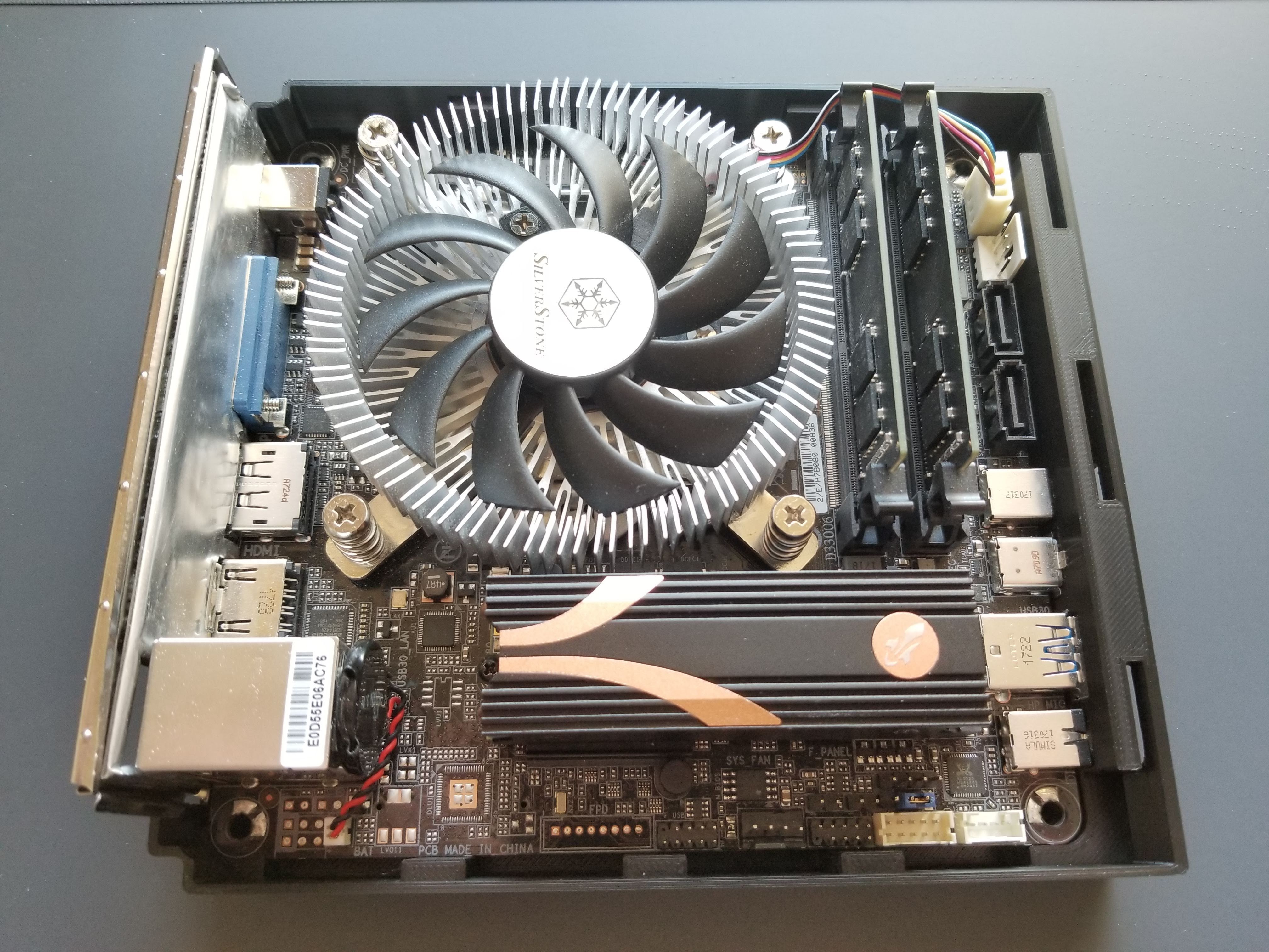
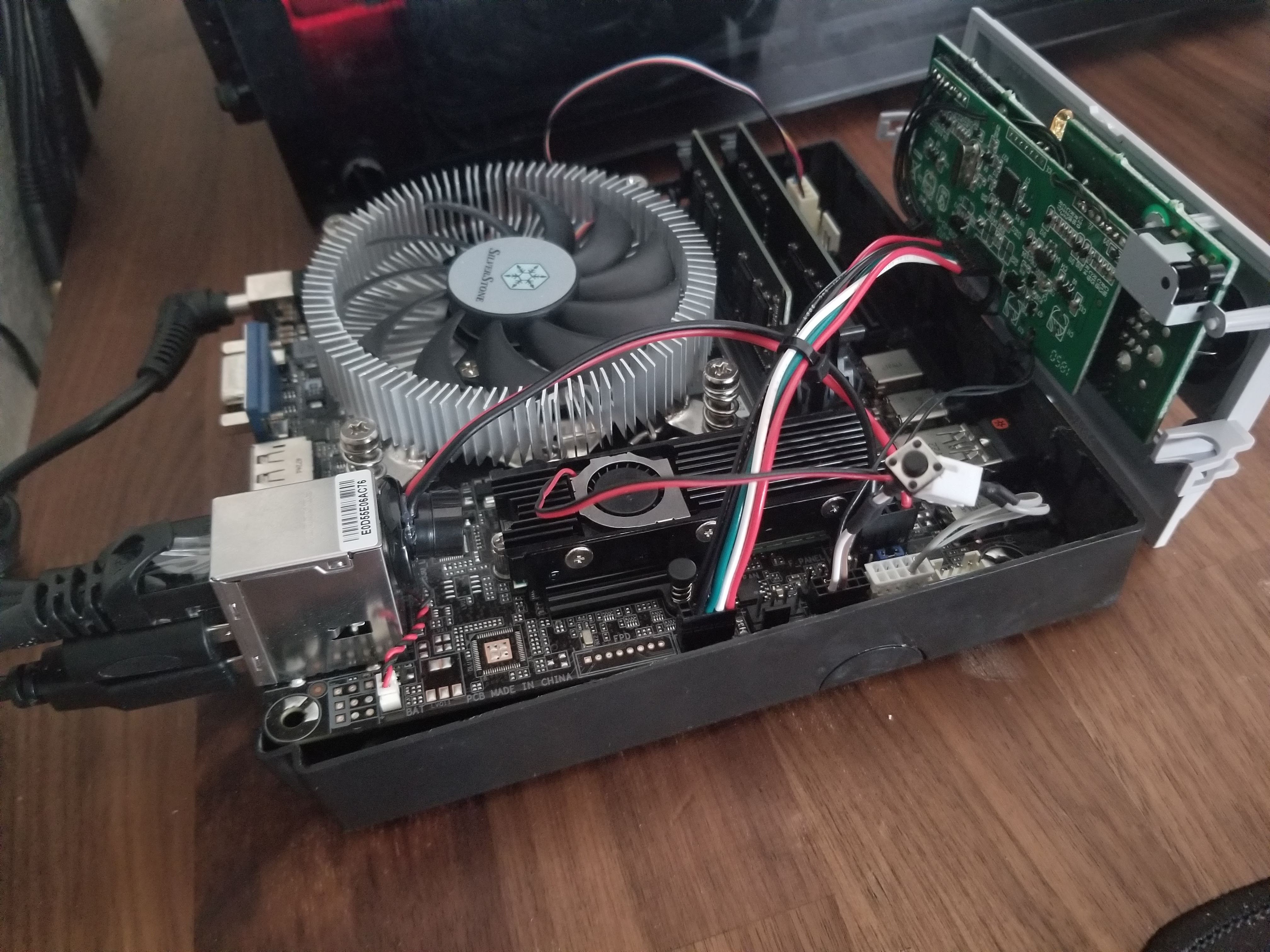
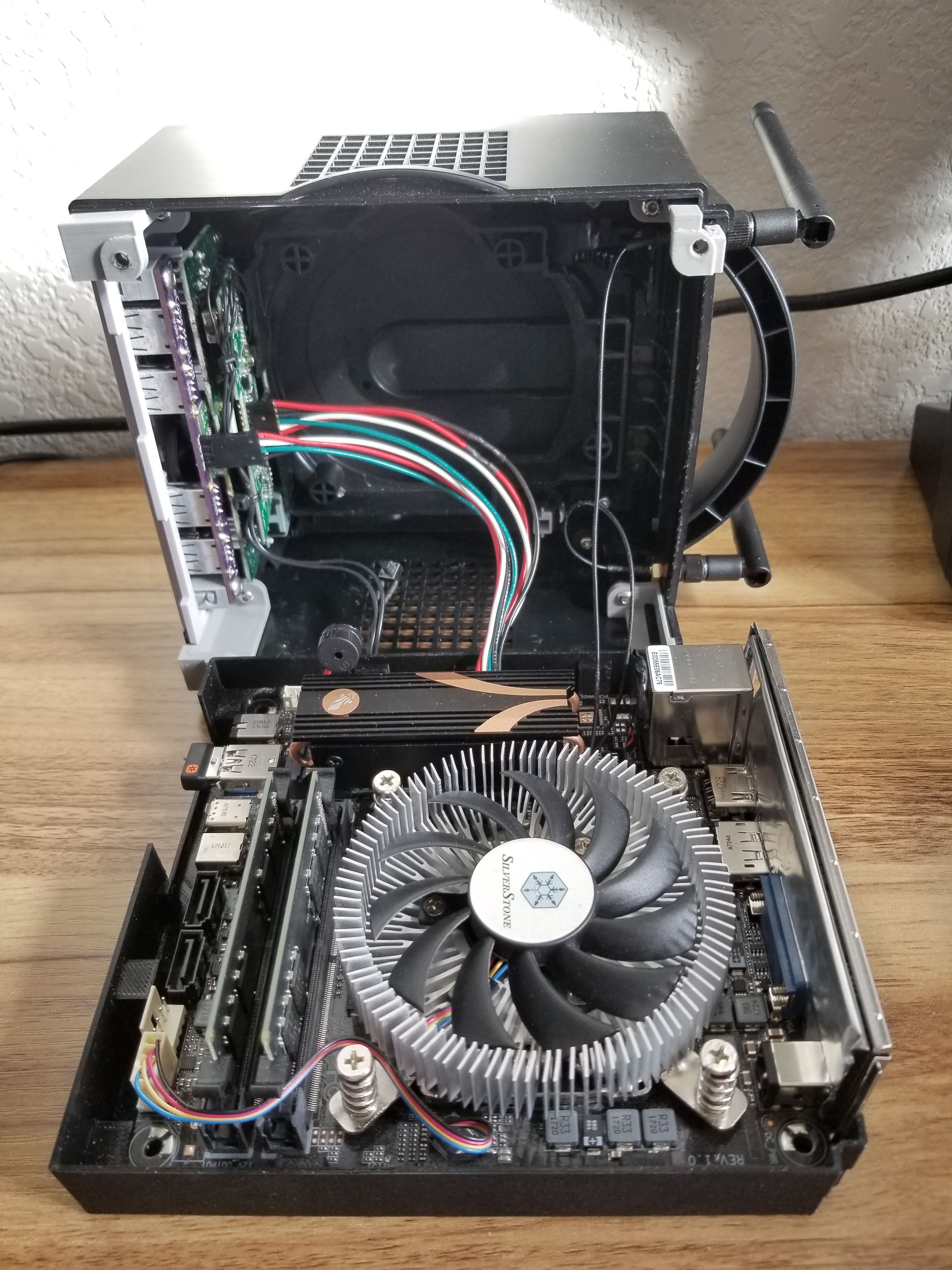
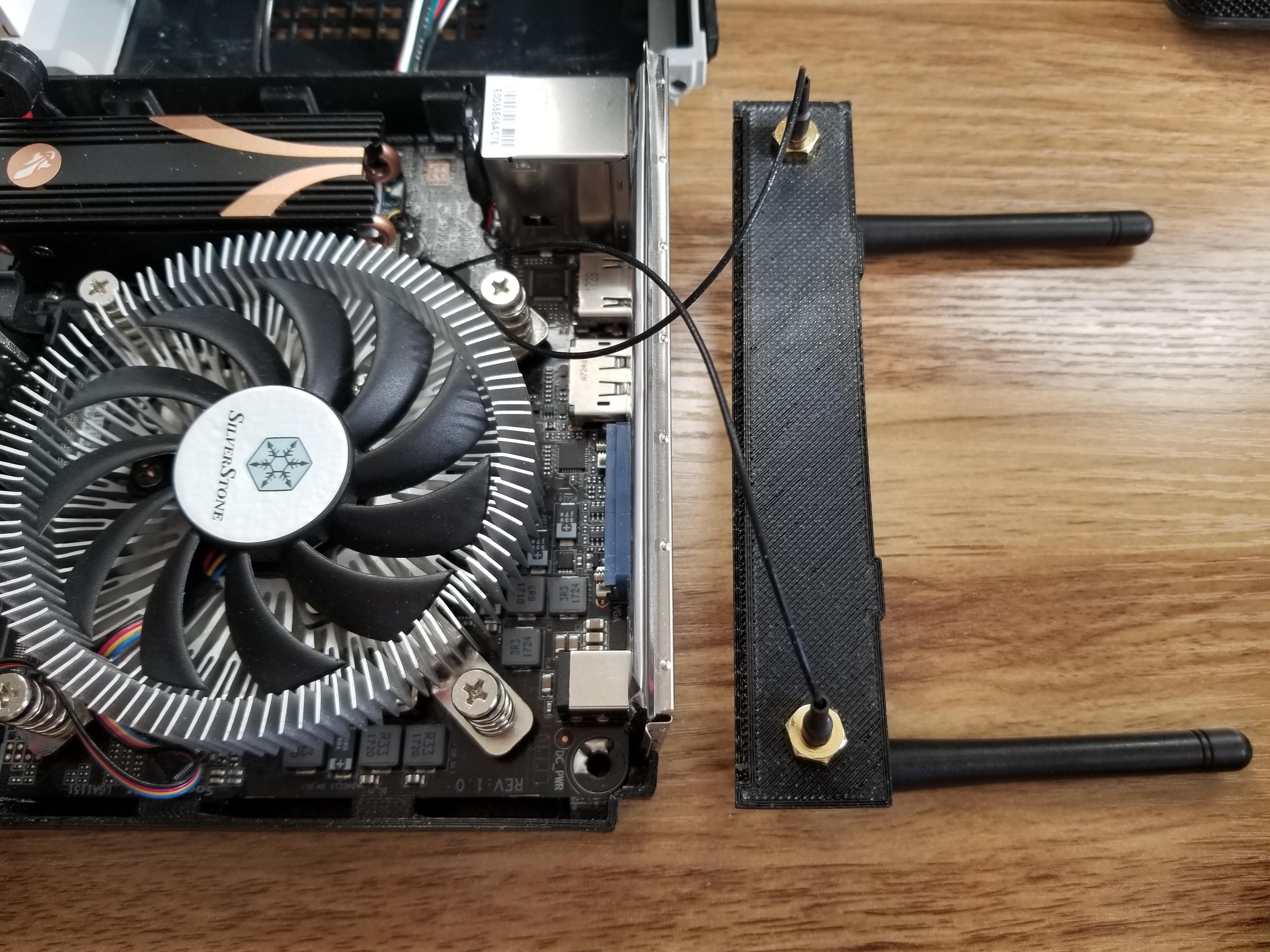
The mSTX version can support a variety of processors, 260-pin SO-DIMM RAM, and either NVMe or SATA storage depending on the M.2 port specifications. The computer is powered externally through a 19V DC barrel jack power supply. Video output is provided by on-board DisplayPort, HDMI, and VGA ports in the back, and audio input/output can be accessed through the 3.5mm jacks in the front. An optional M.2 WiFi/Bluetooth module can be added with the antennas mounted to a custom rear cover plate that sits above the rear I/O shield.
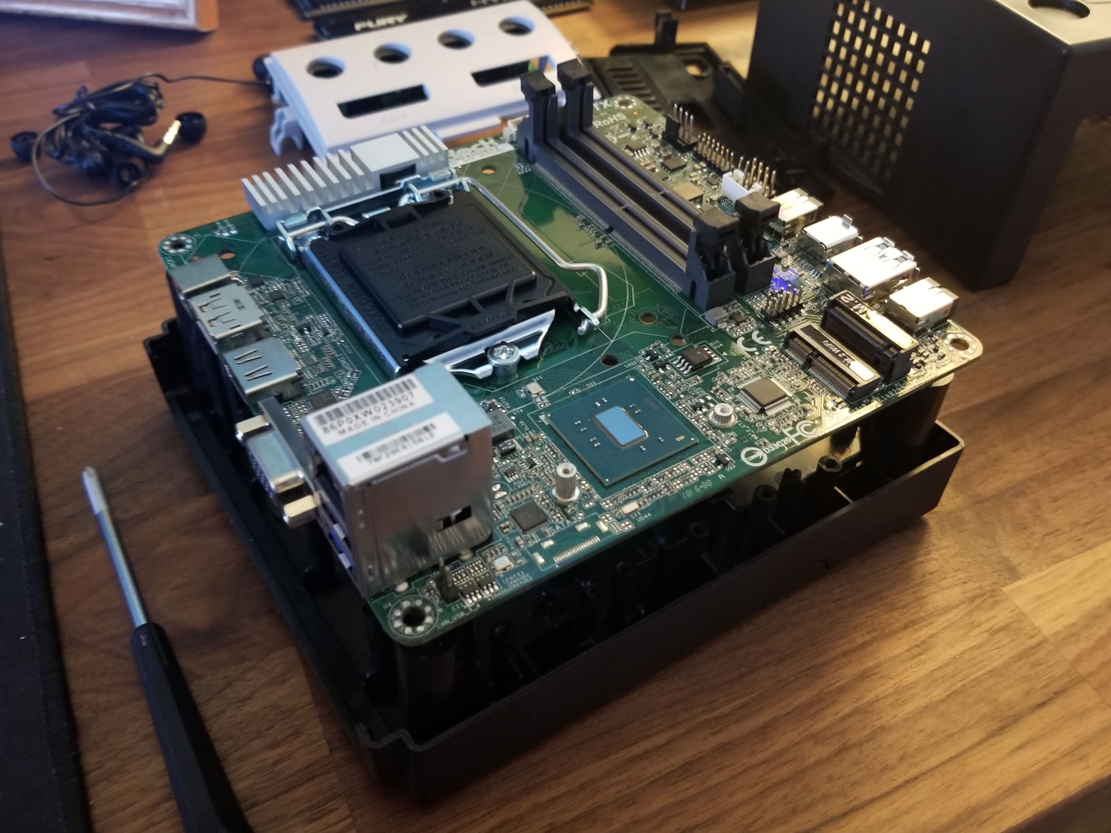
The NUC version is currently limited to the Intel NUC7 Mainstream Kit (NUC7i5BNK) which has a core i5-7260U dual-core processor and in a lot of ways, can out-perform the mSTX builds. Similarly it accepts 260-pin SO-DIMM laptop RAM and SATA storage through the M.2 port.
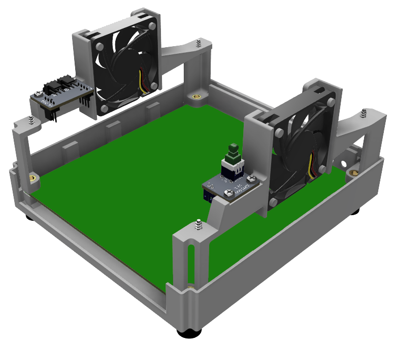
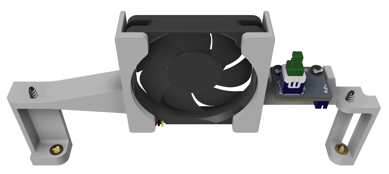
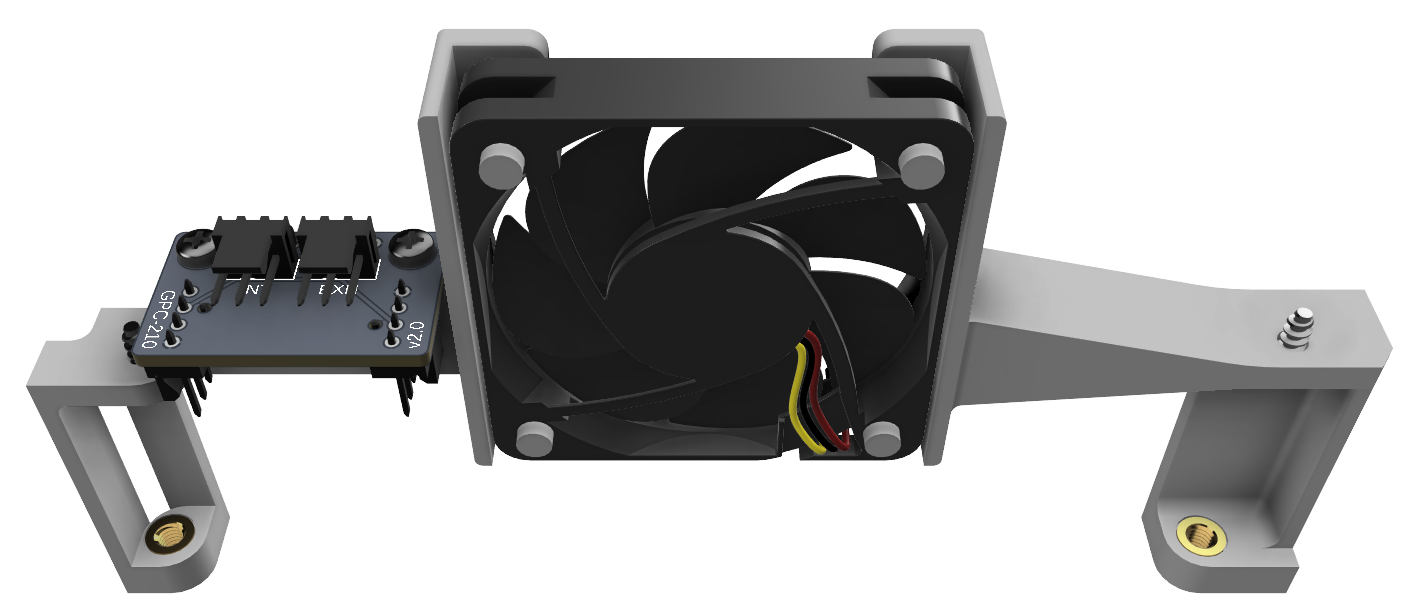
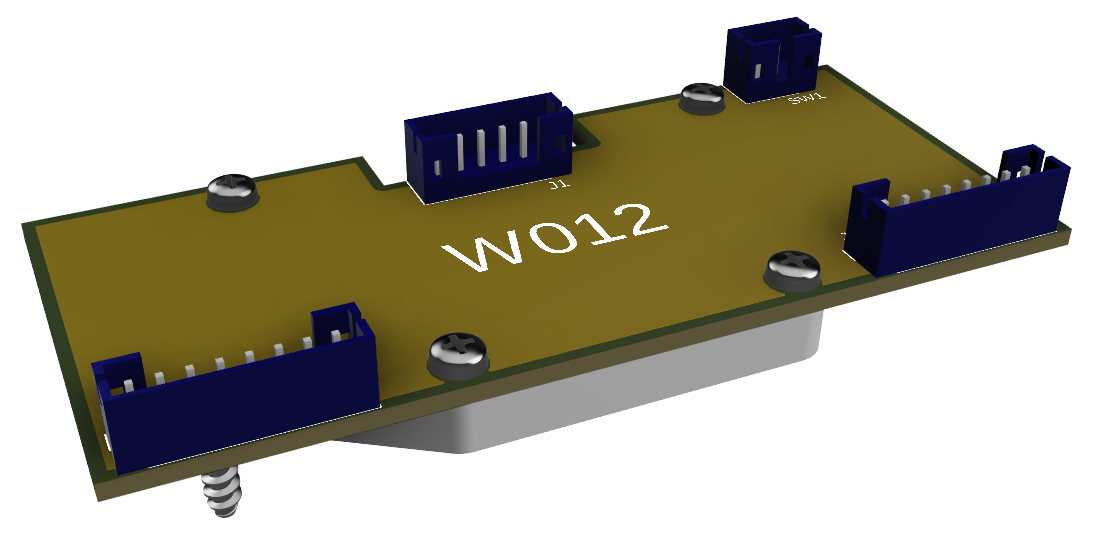
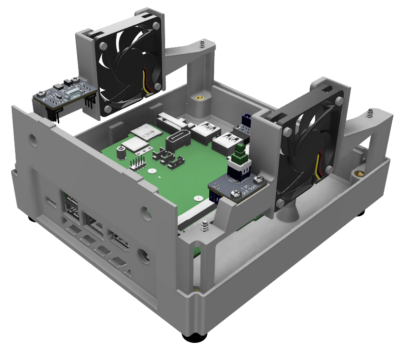
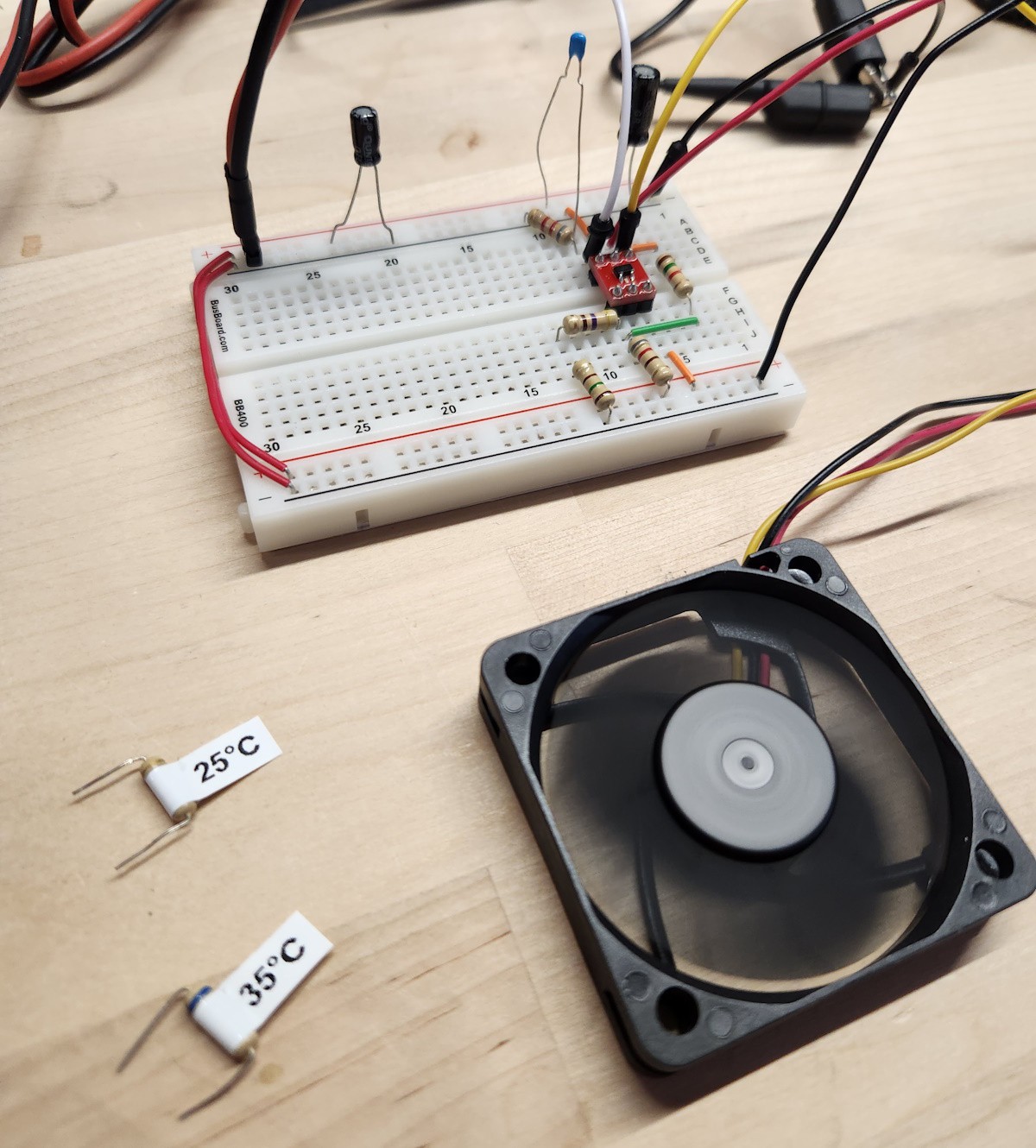
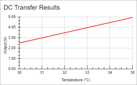
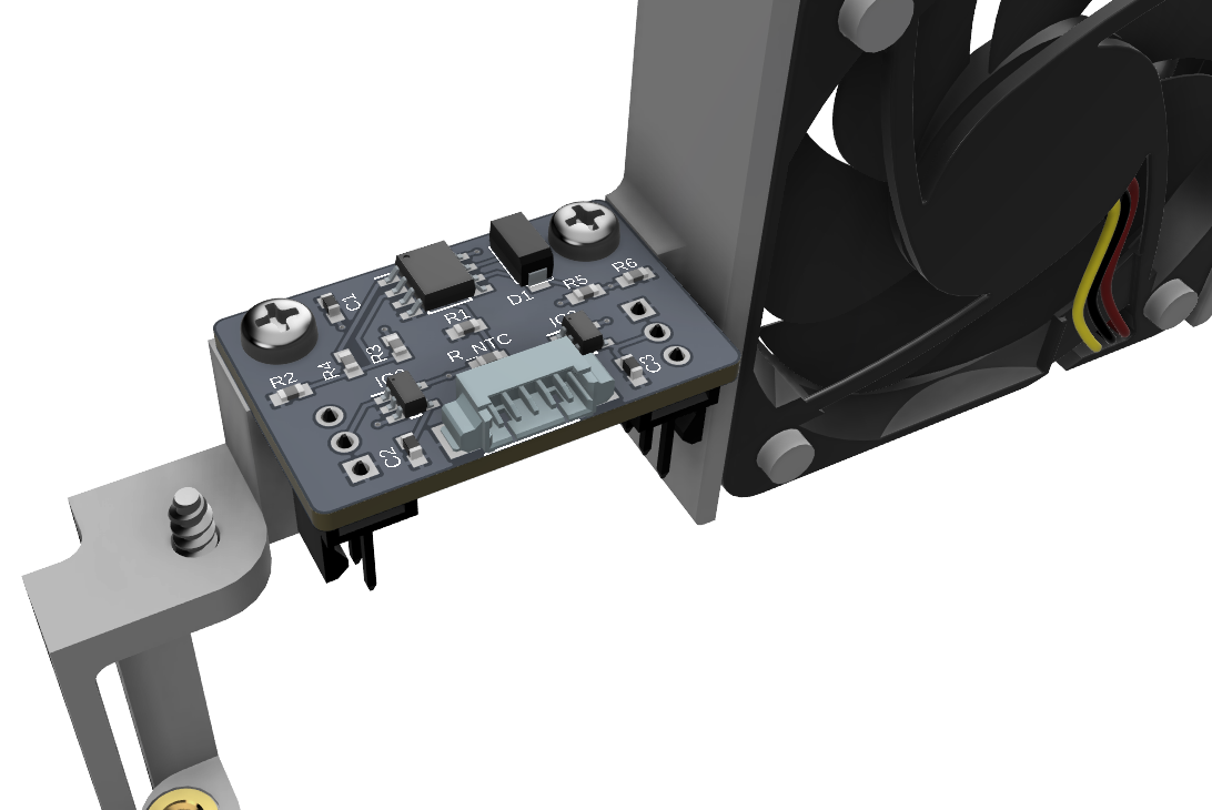
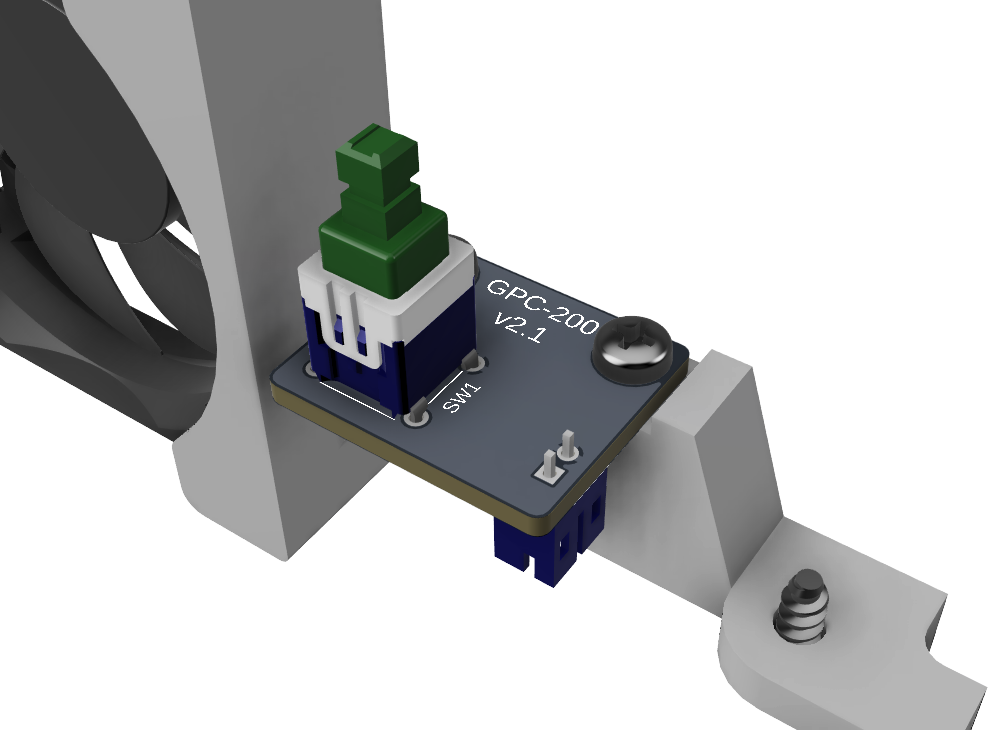
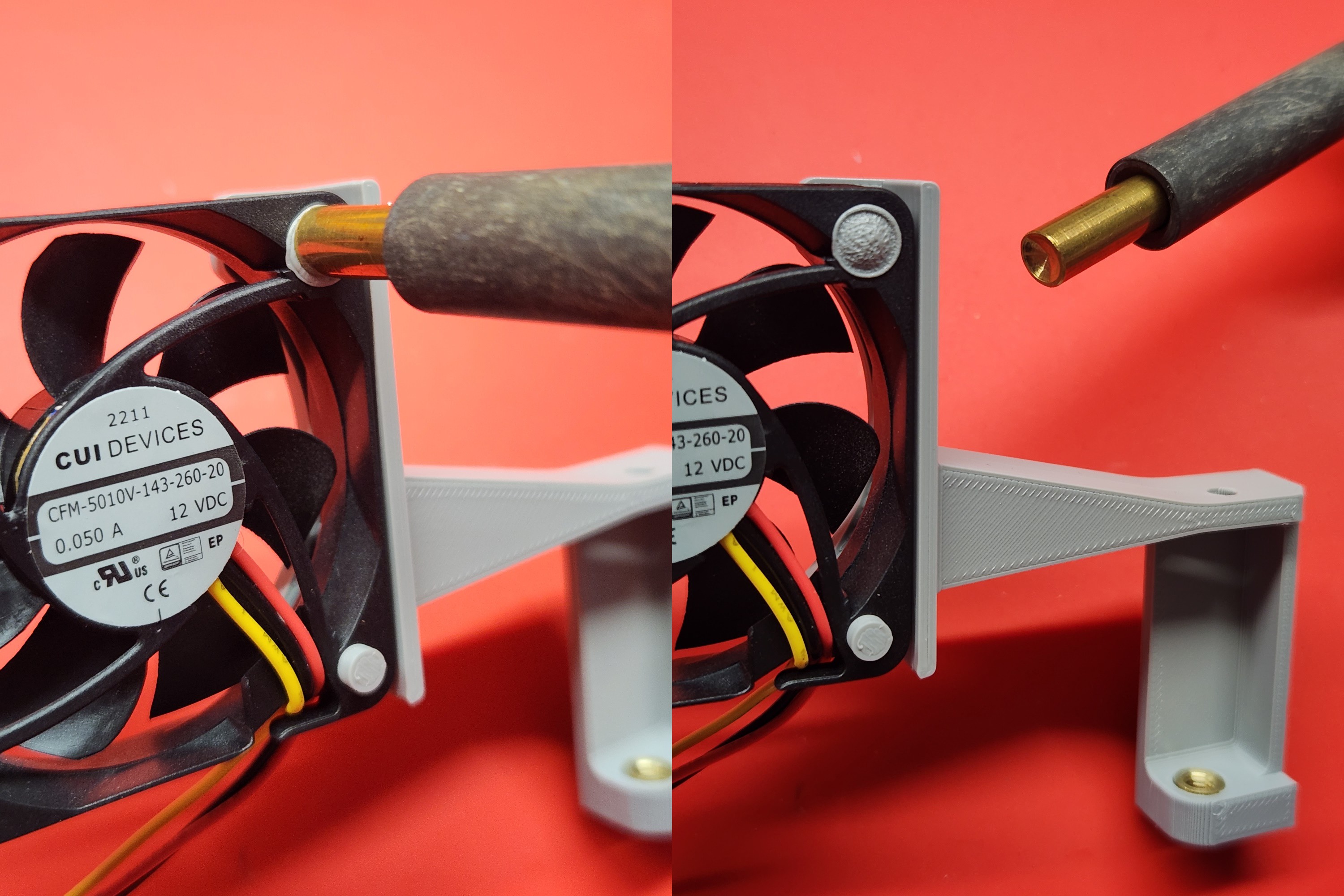
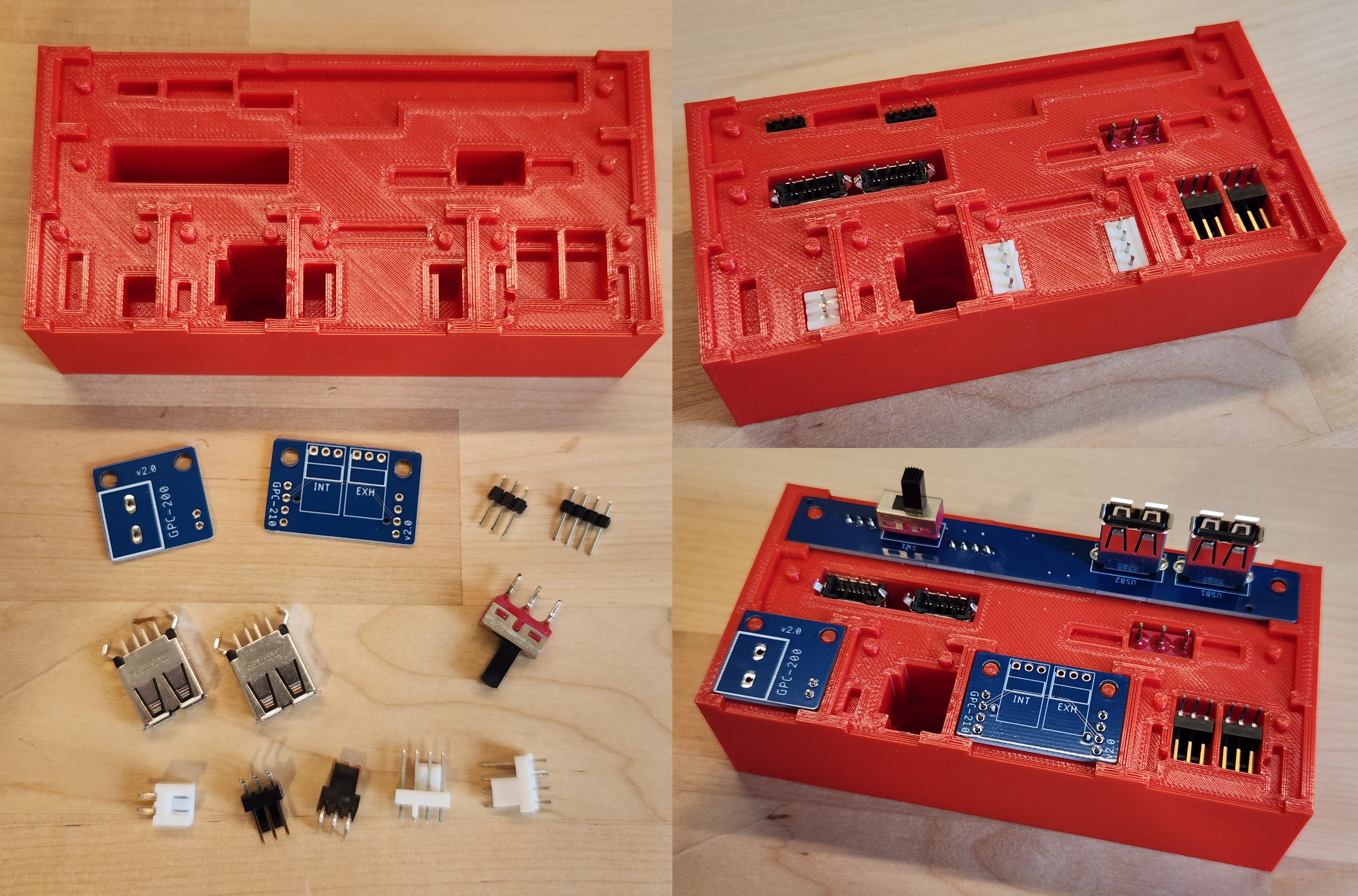
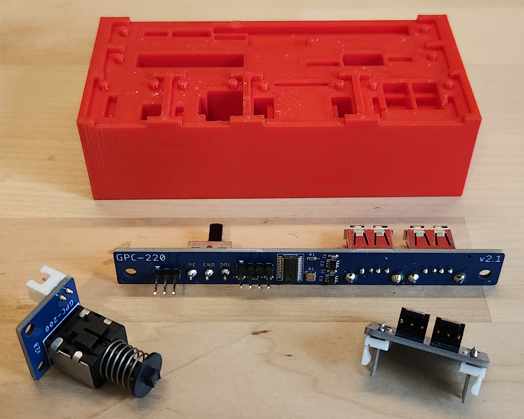
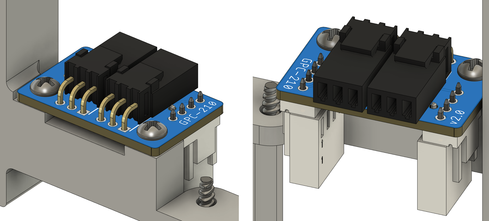
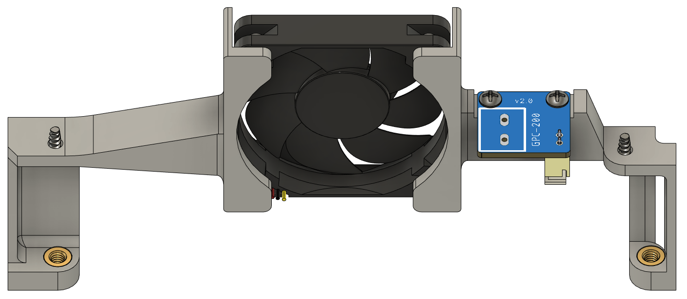
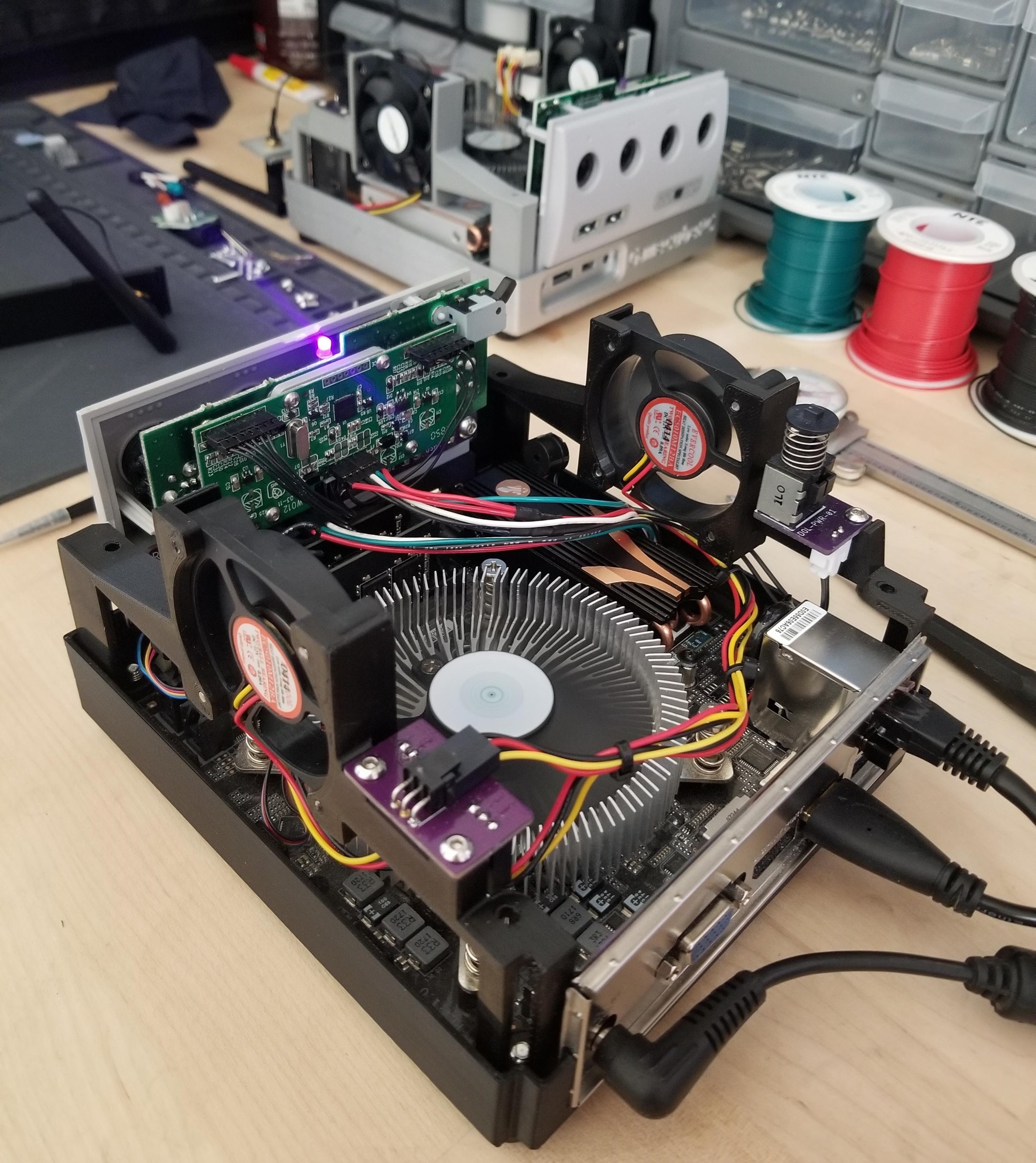
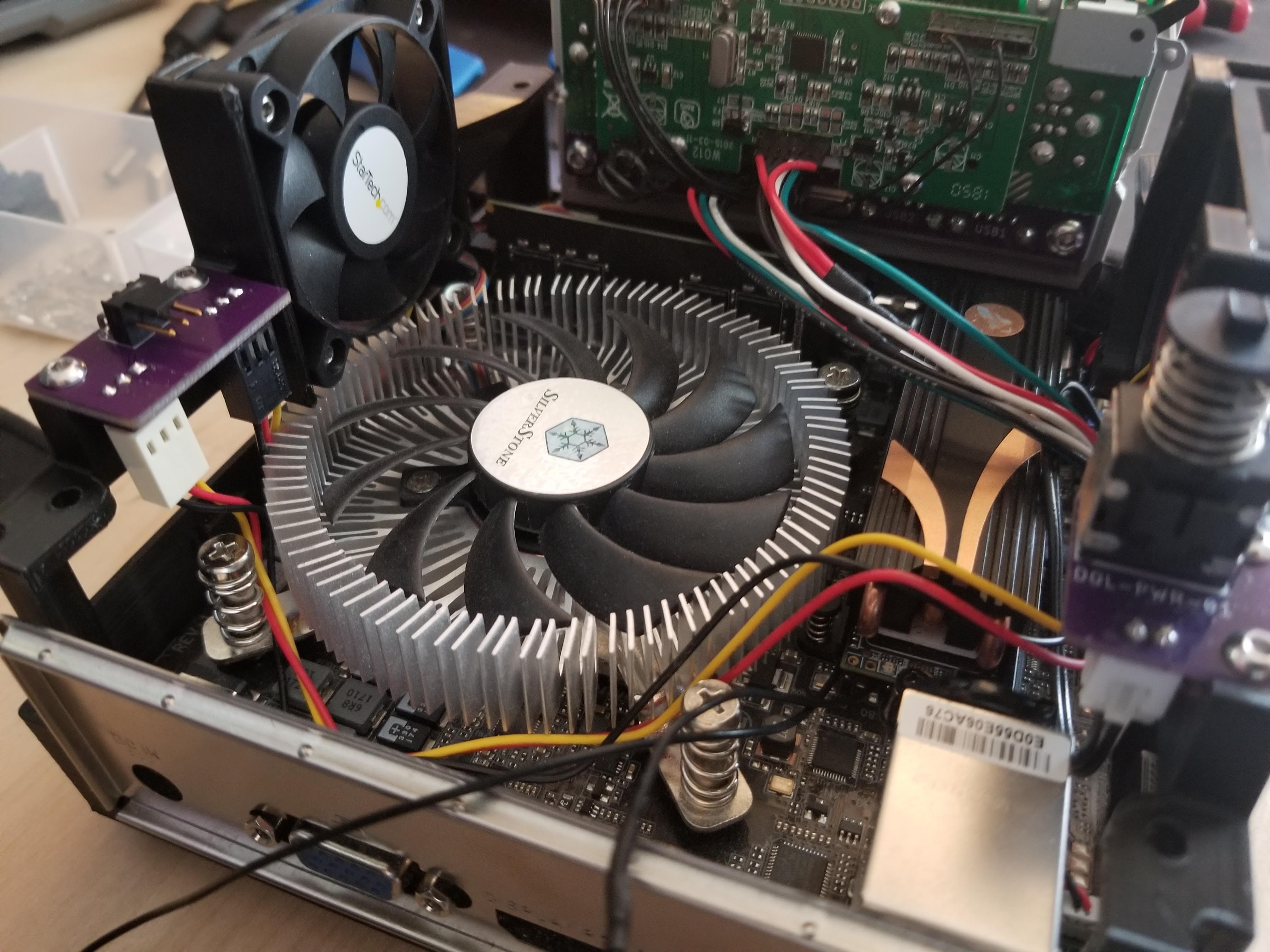
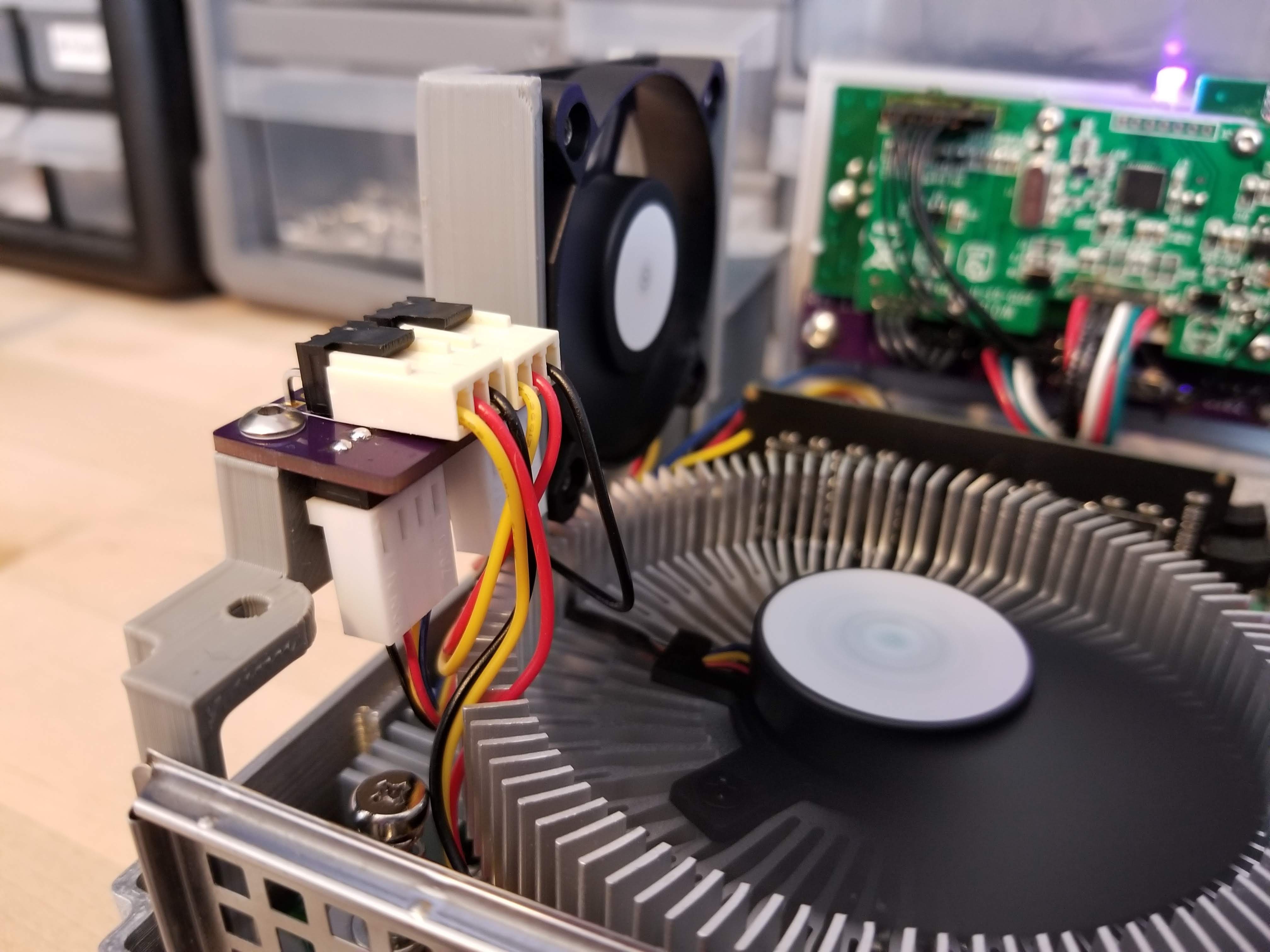
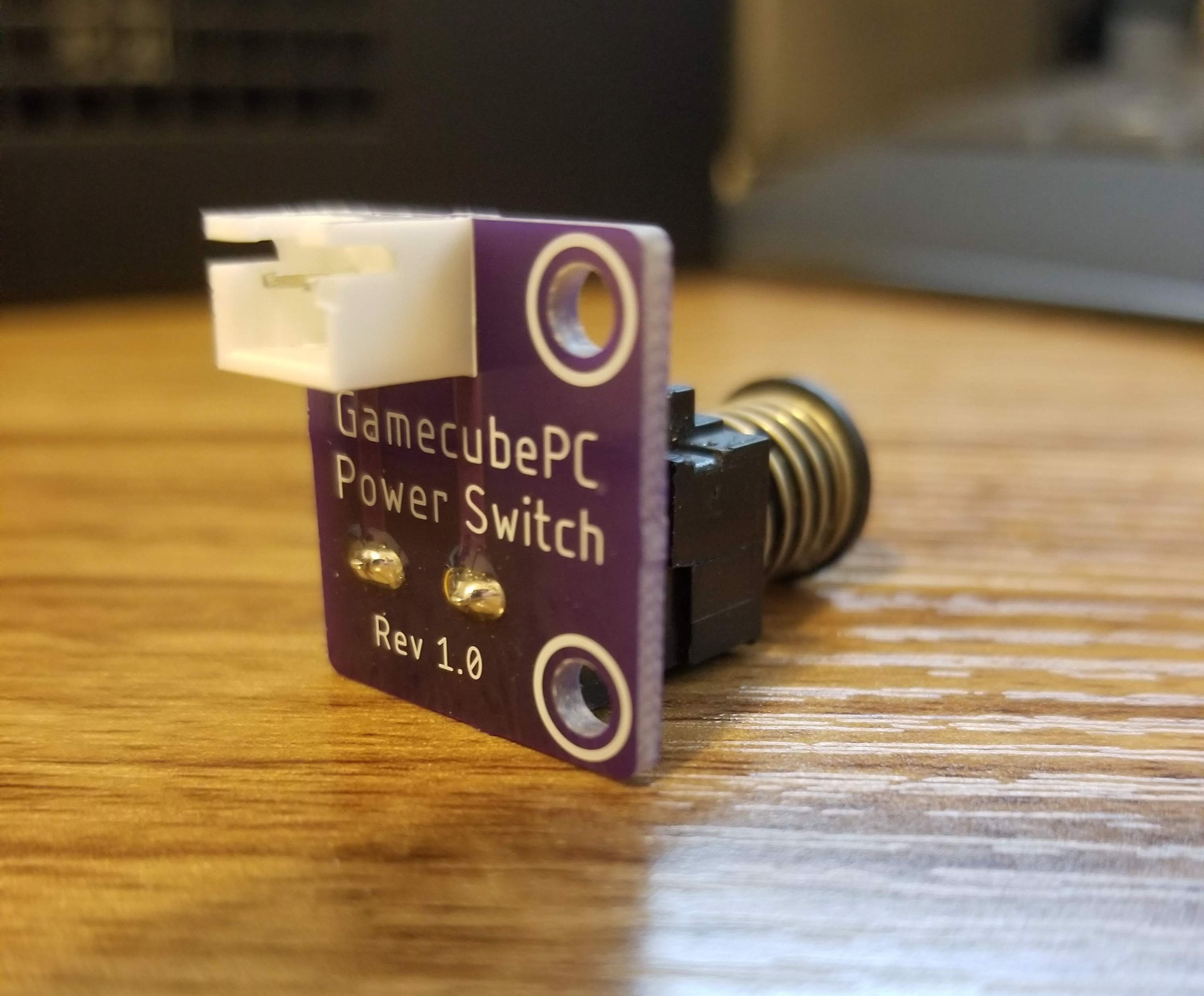
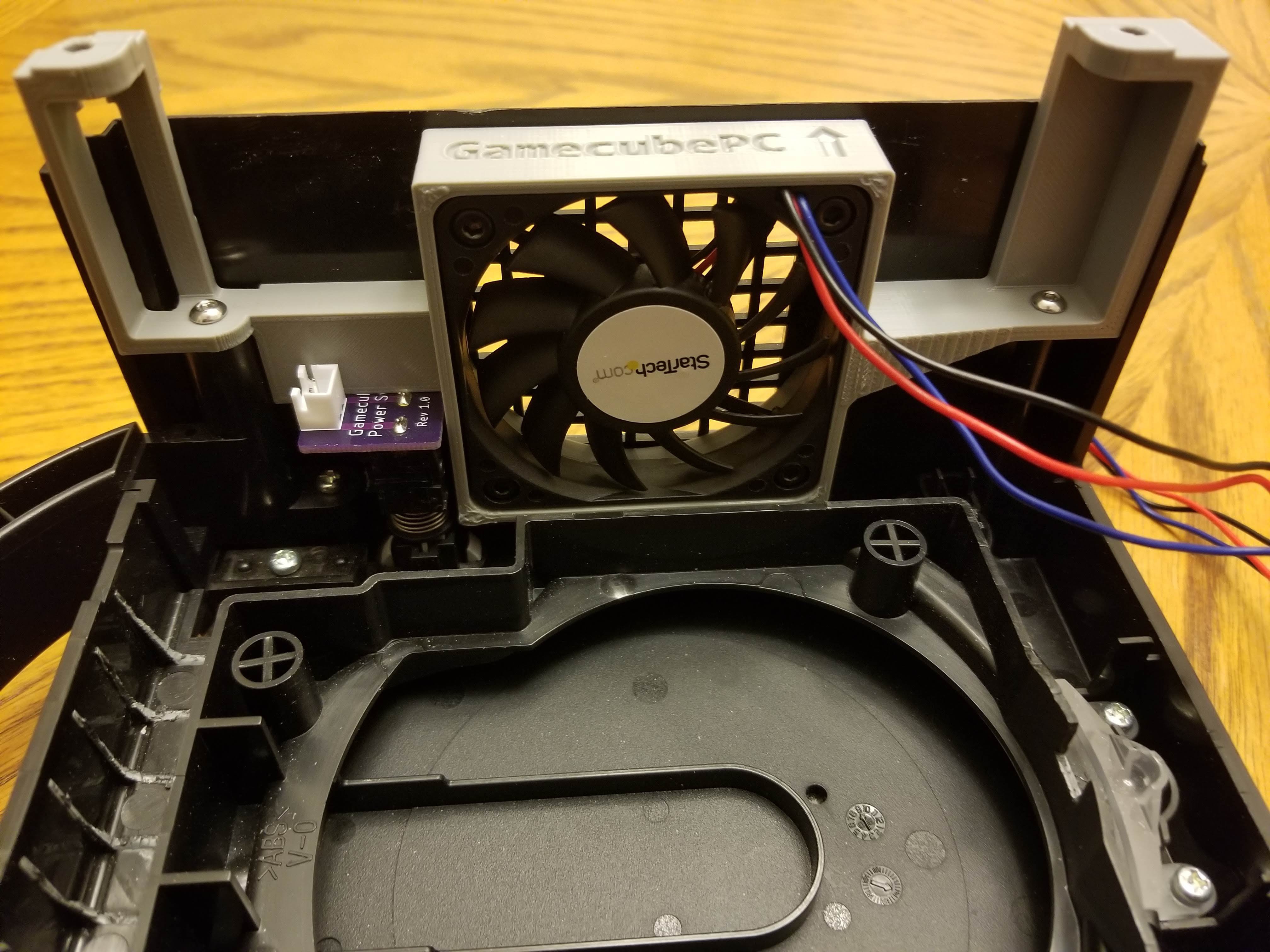
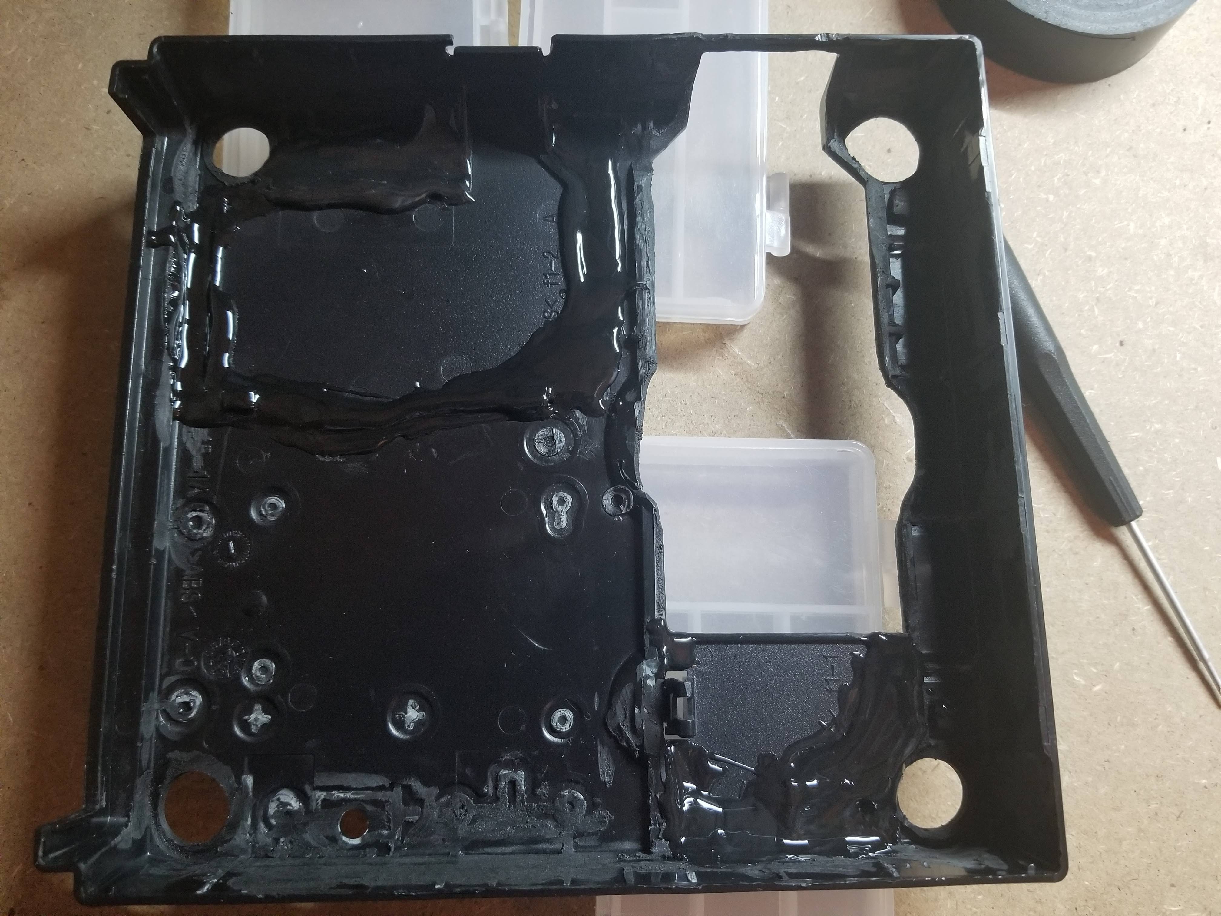
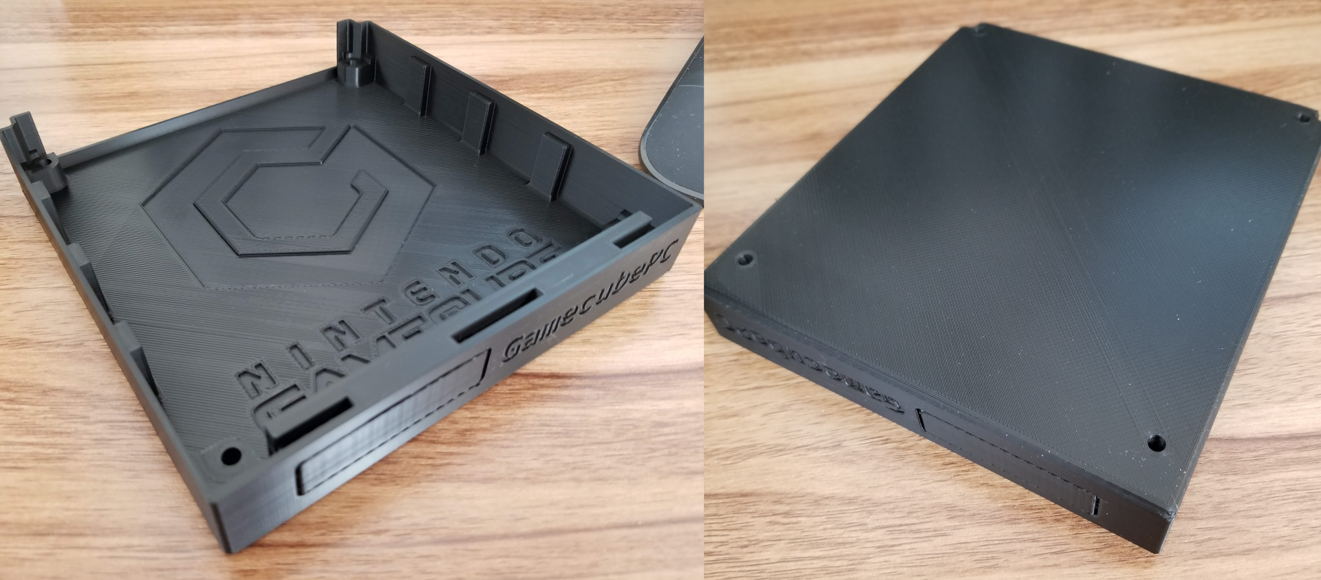
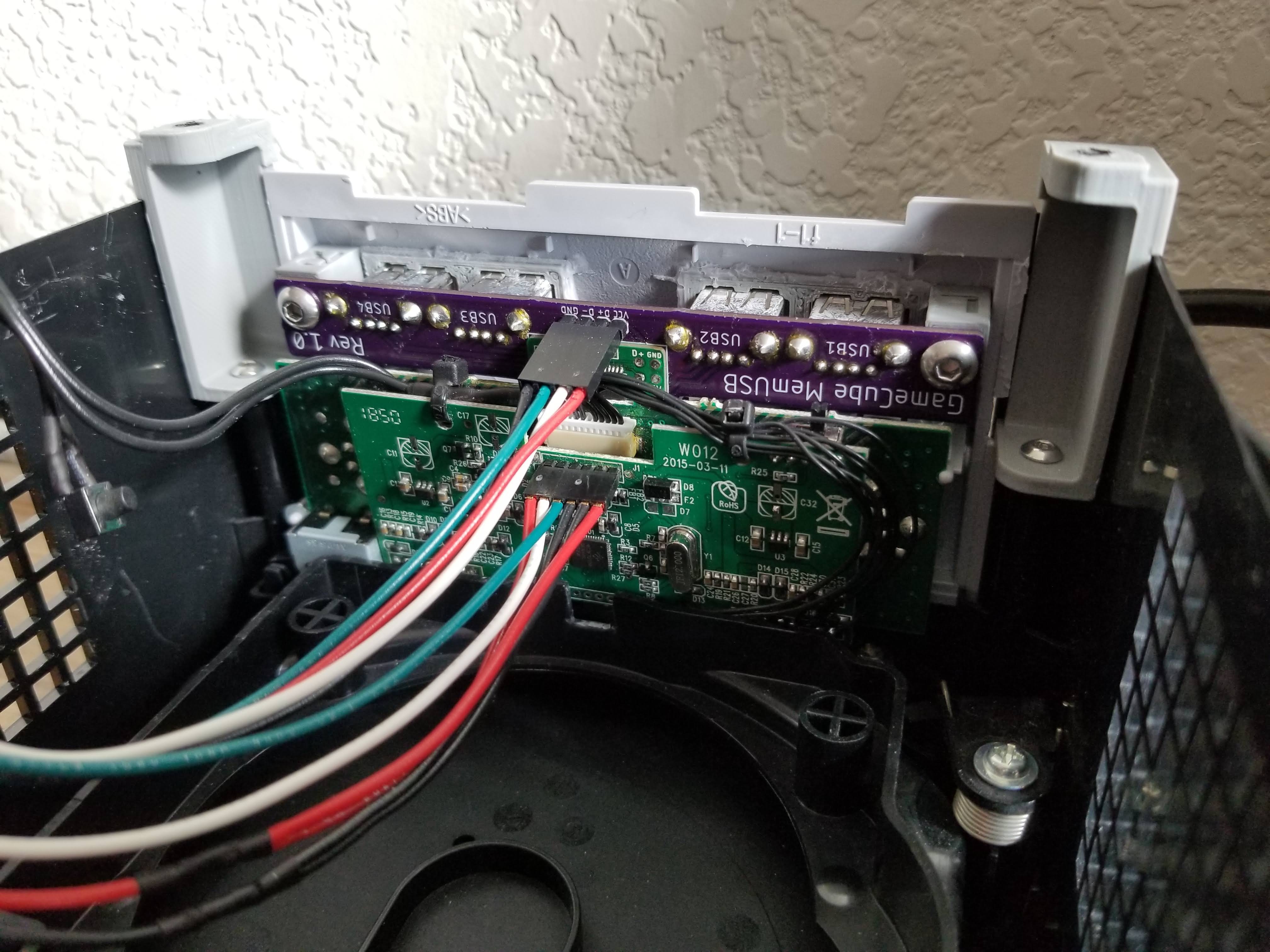
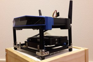
The 3D printed bottom shell has been designed to both match the footprint of the top shell as well as provide a shelf for the motherboard to rest on. In the mSTX version, the motherboard is held in place by the standoffs that adapt the bottom shell to the original top shell. These standoffs also provide mounting points for 50mm intake and exhaust fans through the original top shell’s side vents. The rear standoffs include shelves to mount two custom circuit boards. The intake-side PCB positions the original power switch right below the button in the top shell. For the mSTX version, the exhaust-side PCB provides a fan hub to distribute the PWM fan signal from the motherboard to the 50mm fans, as well as the CPU fan for motherboards that only have one CPU fan header. For the NUC7 version, the exhaust-side PCB provides power to the fans but also controls their speed based on the case's ambient air temp, with a minimum speed setpoint that the fans will never drop below.
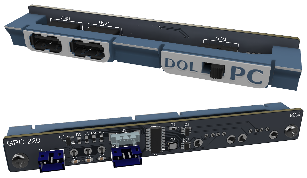
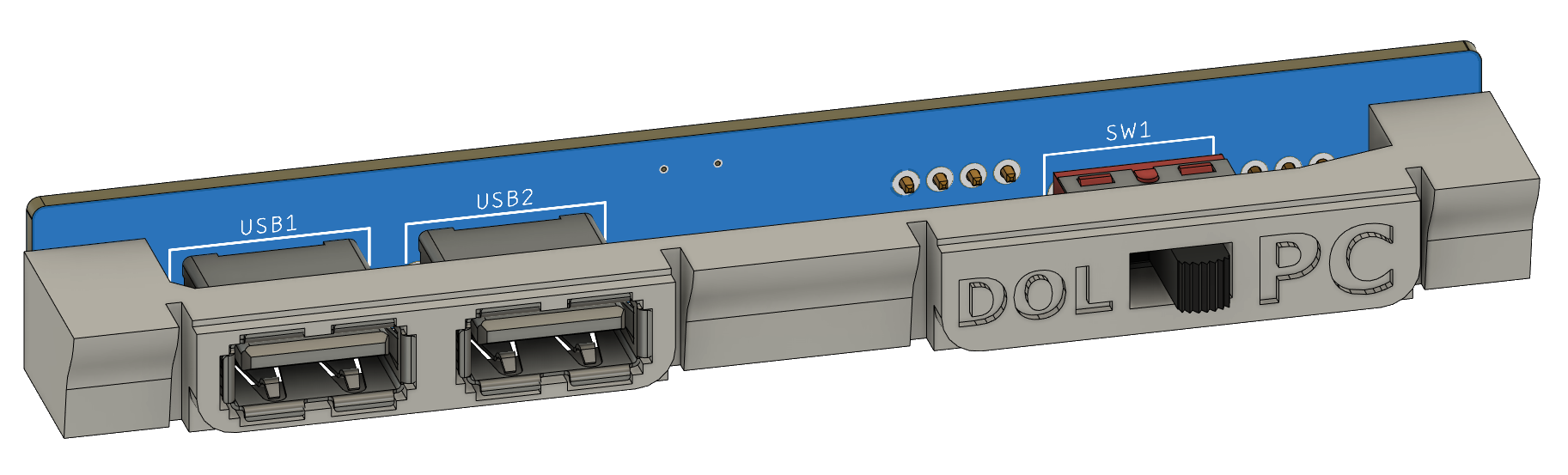
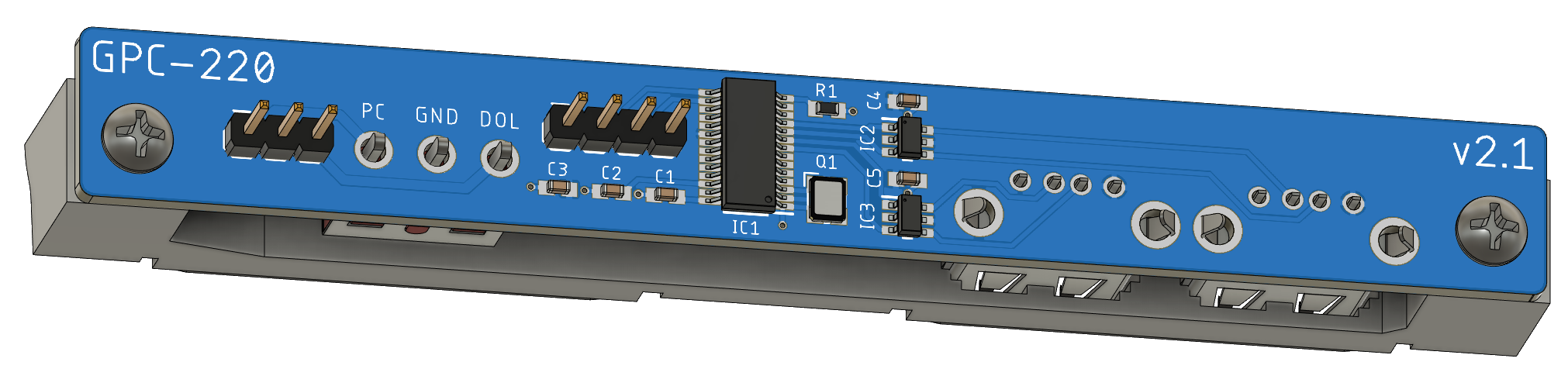
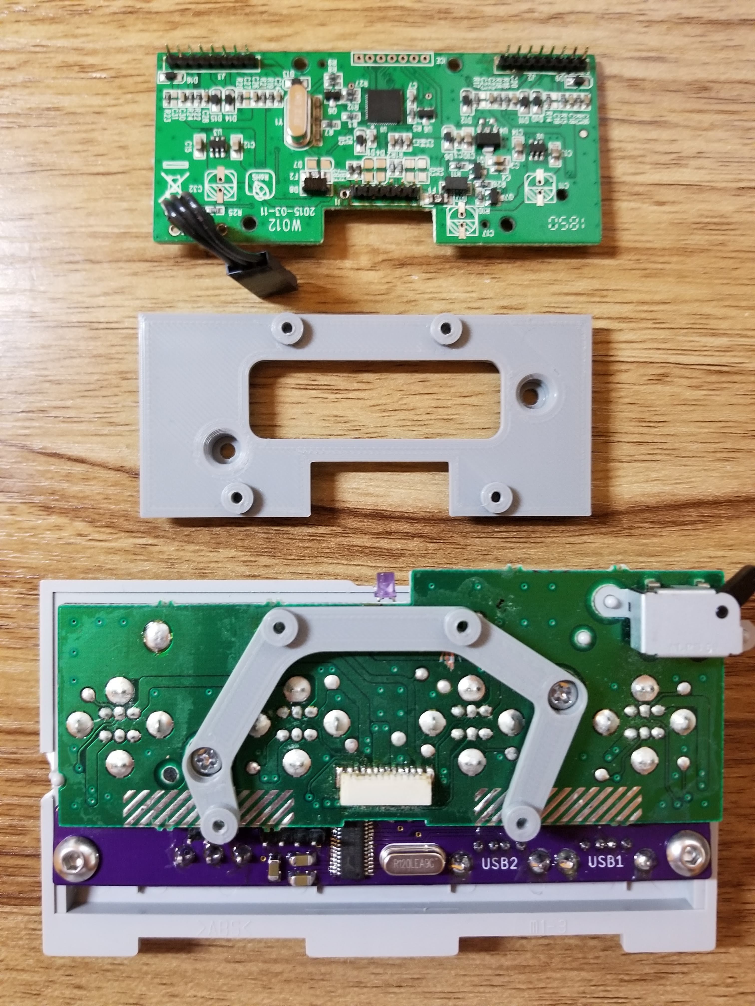
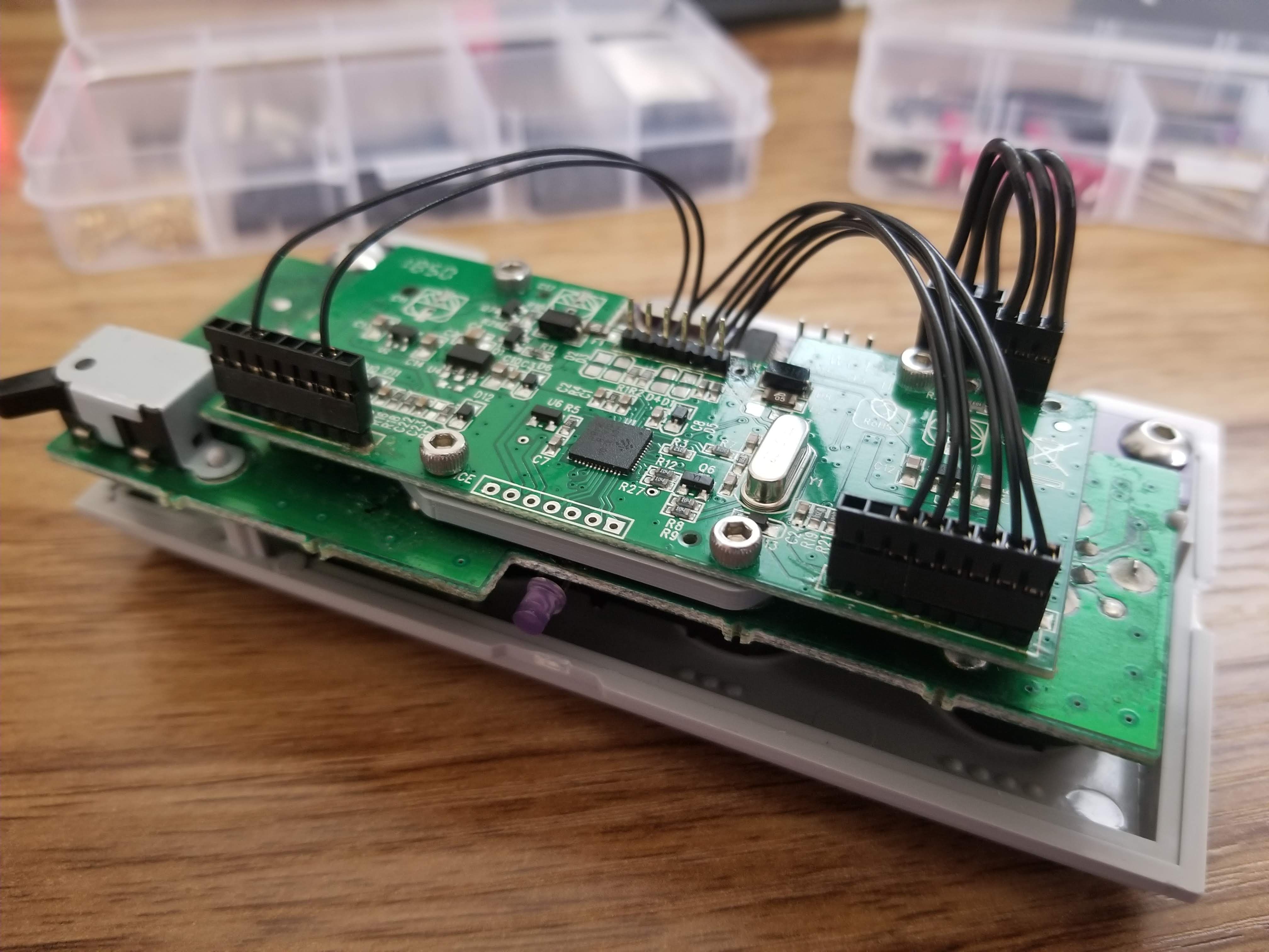
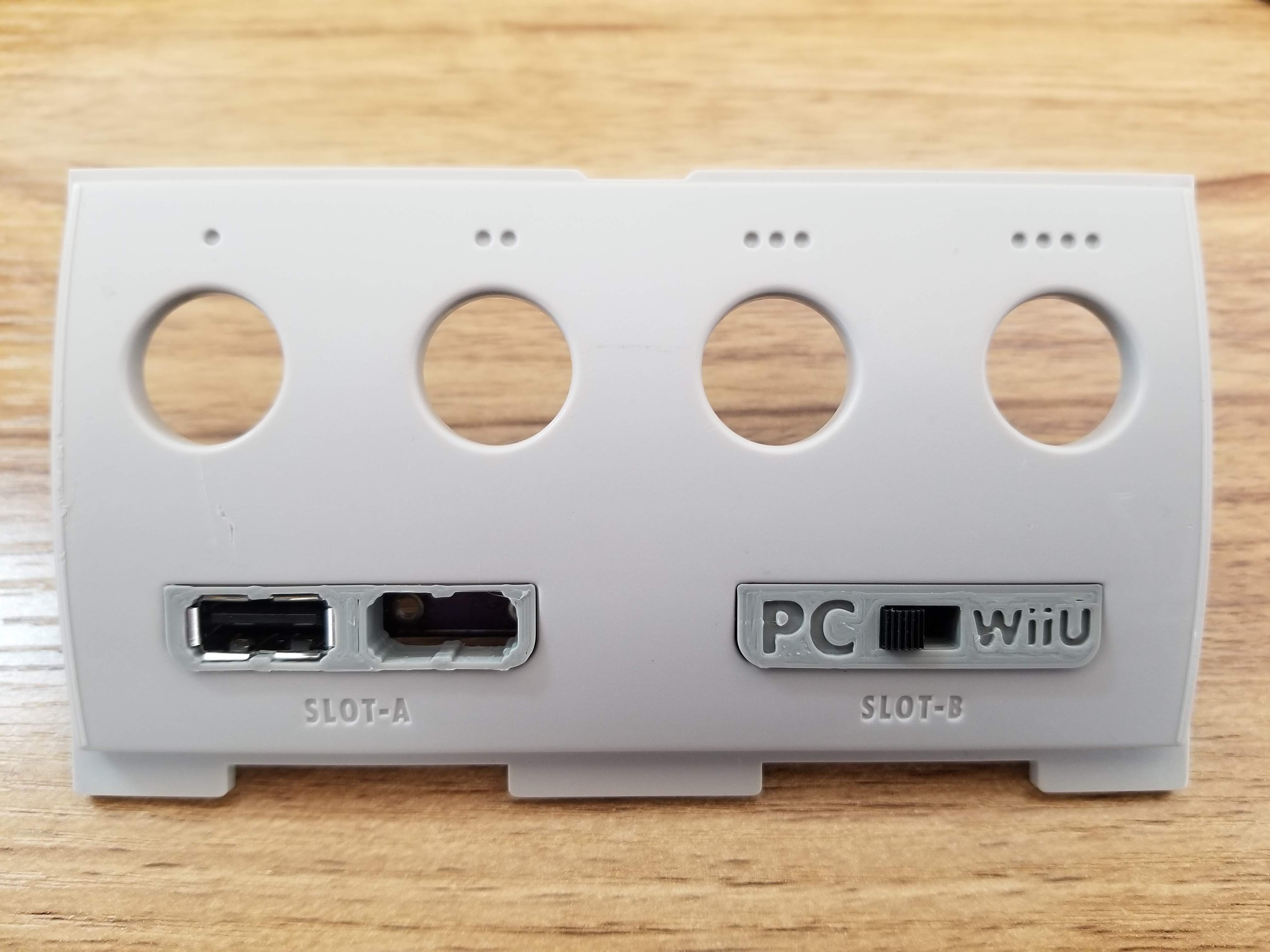
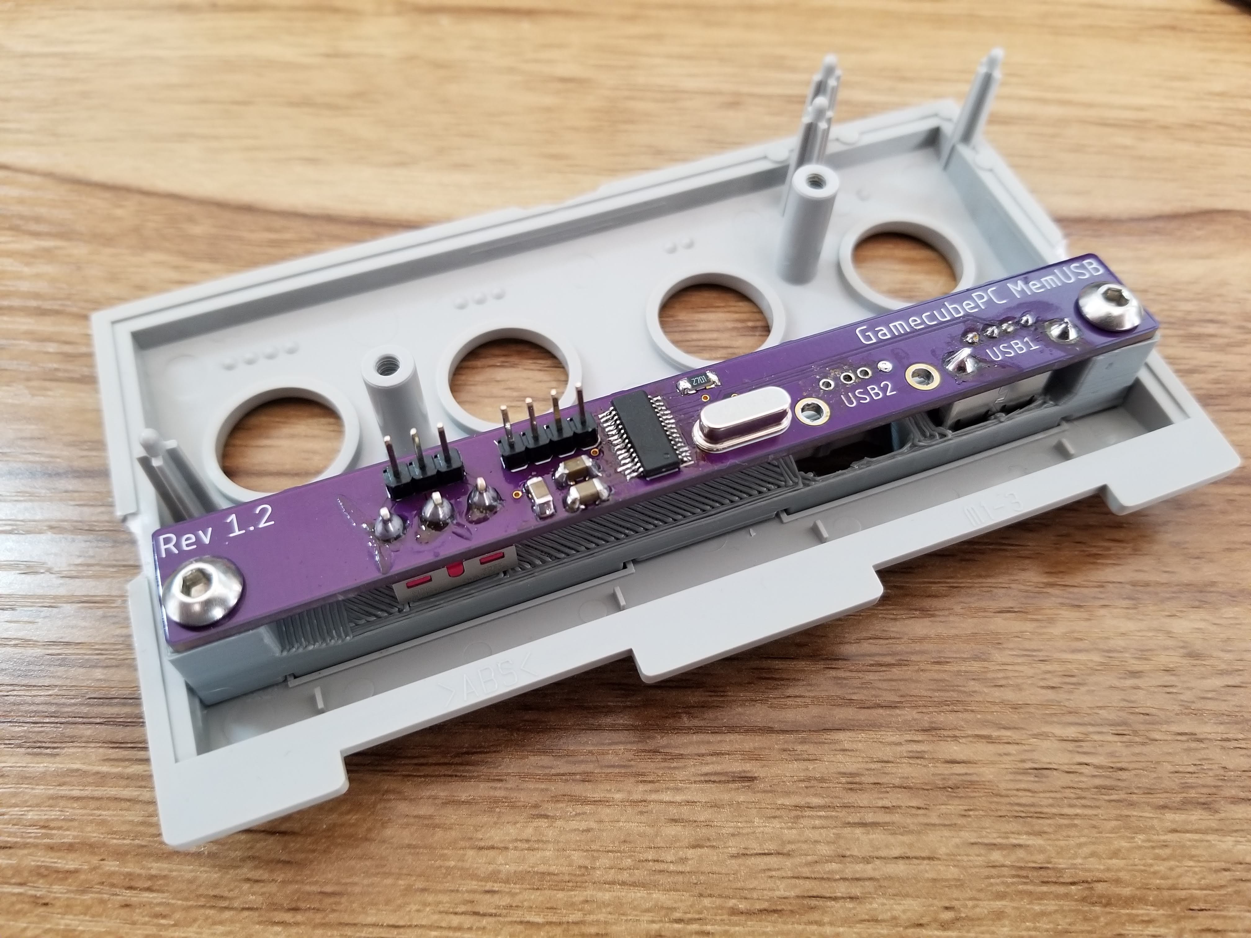
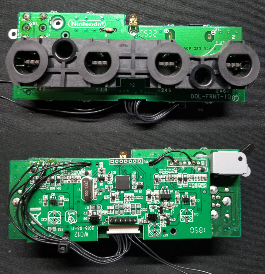
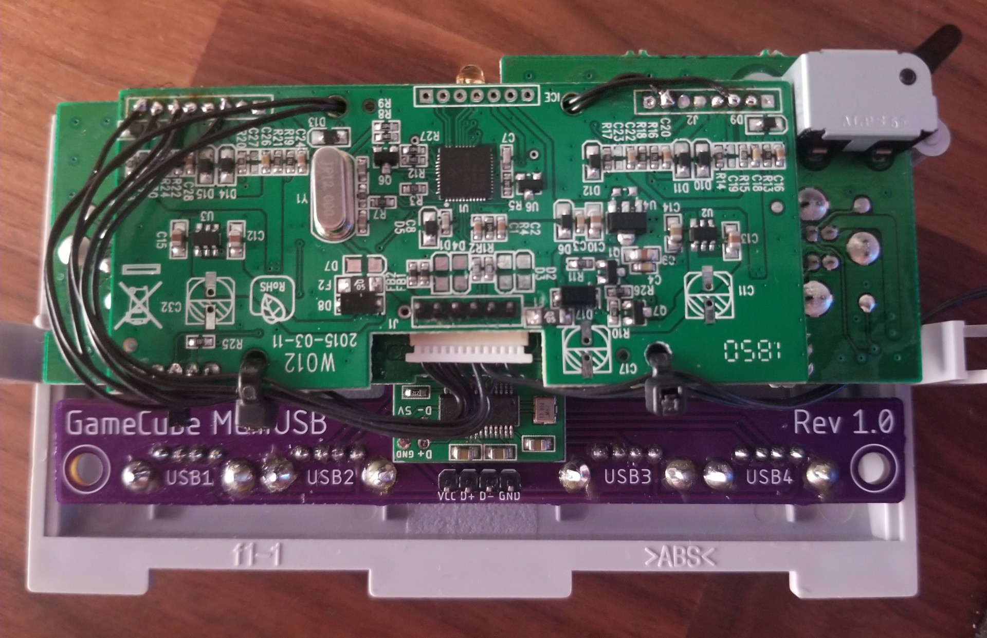
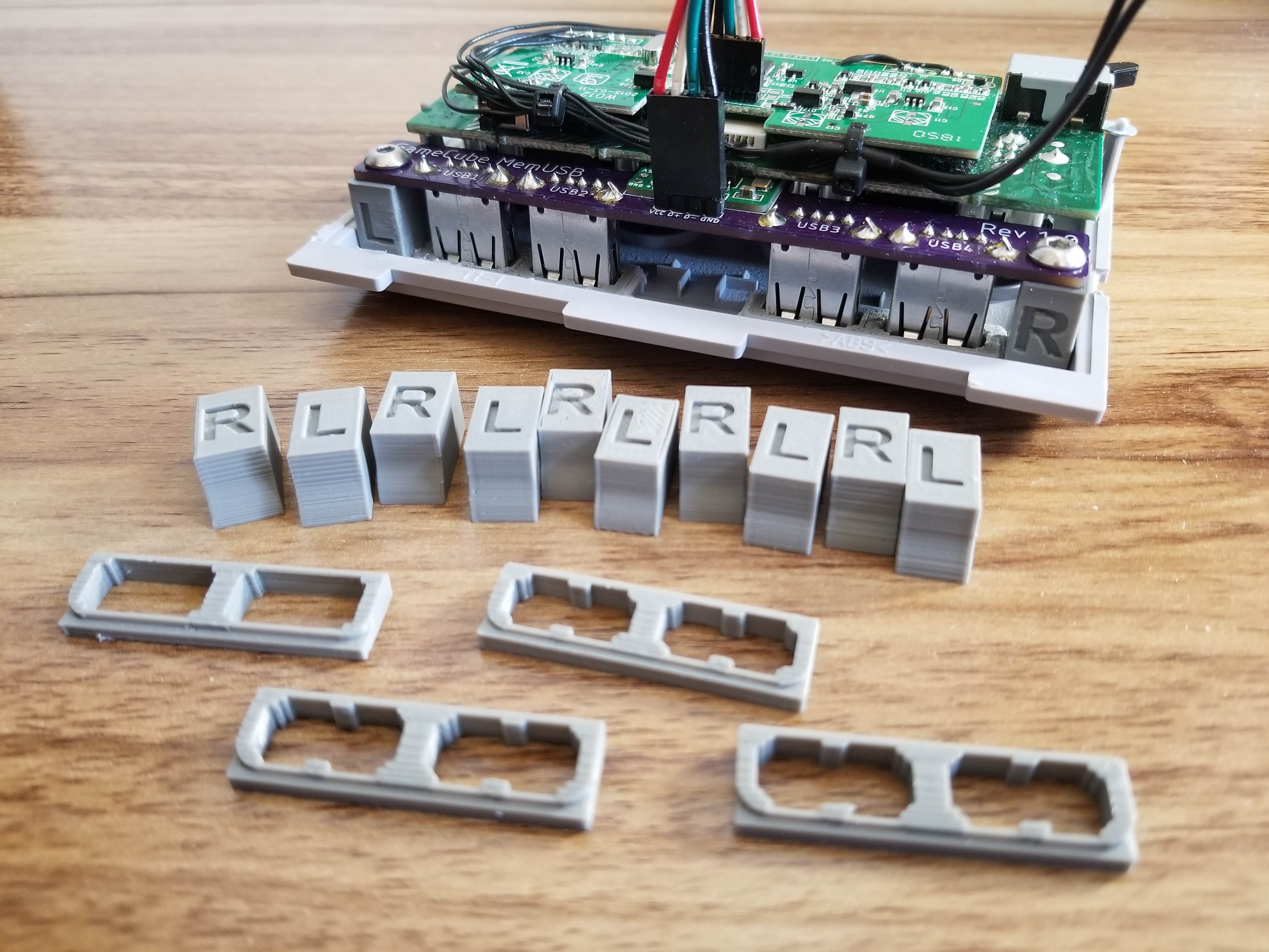
The controller ports are accessible through a USB adapter mounted and wired to the back of the original controller port board. The original memory card slots are now used to access to a 2-port USB hub and toggle switch to change the USB controller adapter’s mode.
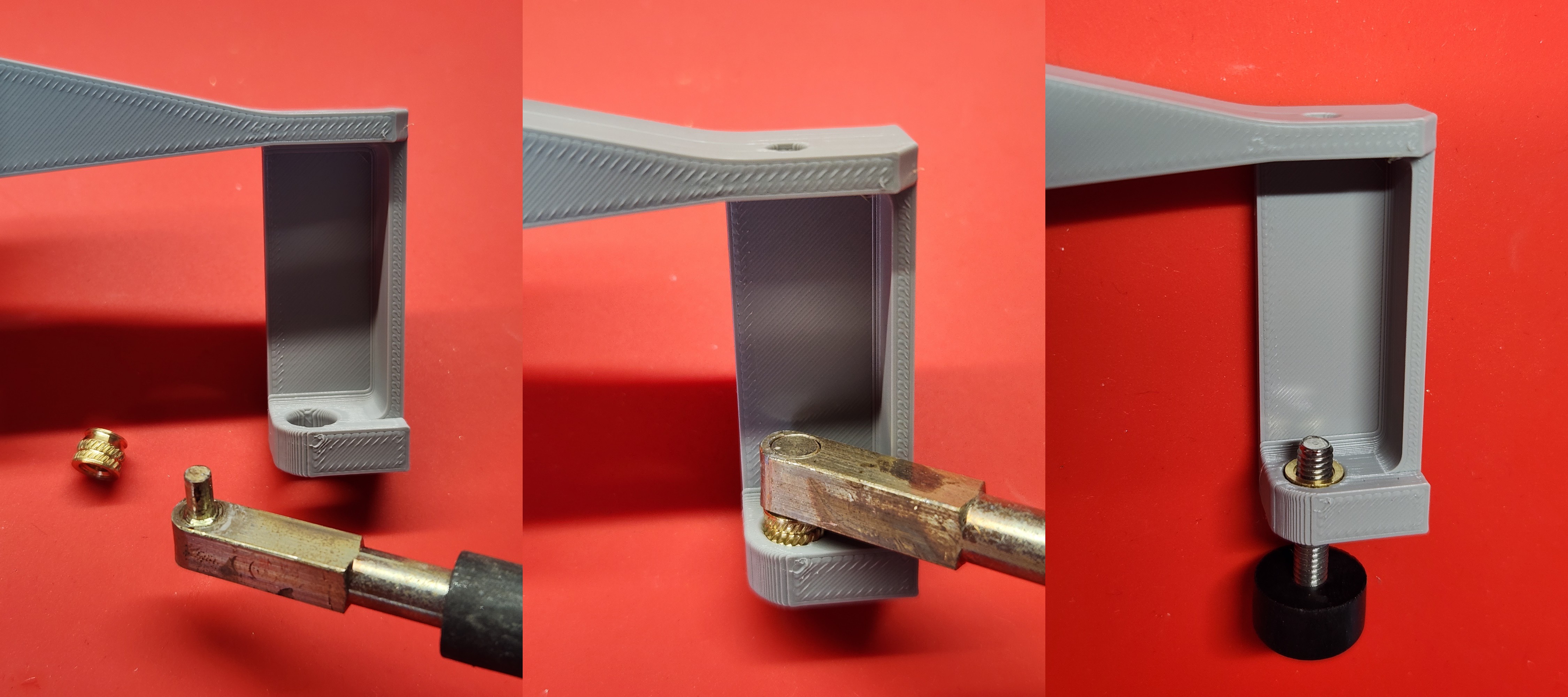
The power and reset switches are wired to the internal front panel header’s power and reset pins. The underside screws that pass through the motherboard are coupled with rubber bumpers under the bottom shell and allow the unit to be stable on its resting surface.
Thank you to the following contributors!
- Shane Marsh
- Alberto Amador
- Helder


 Stanislas Bertrand
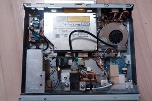
 darth_llamah
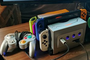
 Tyler
Tyler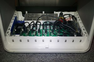
 Paul Nicholls