General overview
With the robot arm fully extended vertically, which is its home pose, its bounding dimensions are approximately 250 mm width, 280 mm depth, 700 mm height. Its estimated mass from the CAD is around 6.5 kg. When fully extended horizontally, its reach is approximately 500 mm. The arm has been tested with a max payload of 0.5 kg. While it was able to pick and place a payload of this mass at near full arm extension, the joint 3 stepper driver was damaged during payload tests of 0.5 kg. Therefore, further testing and possibly mods are needed to ensure a max 0.5 kg payload capability. The robot arm was designed in Fusion 360, and the CAD files (Fusion 360 and STEP format) are available at the following links:
https://github.com/jk87/Open6X/tree/main/CAD/rev1
https://github.com/jk87/Open6X/tree/main/SOFTWARE/rev1
(BoM document to come)
(Wiring diagram to come)
Below are some videos showing an overview of the robot arm together with routines of joints homing, joints sweep and payload pick-and-place.
Mechanical design
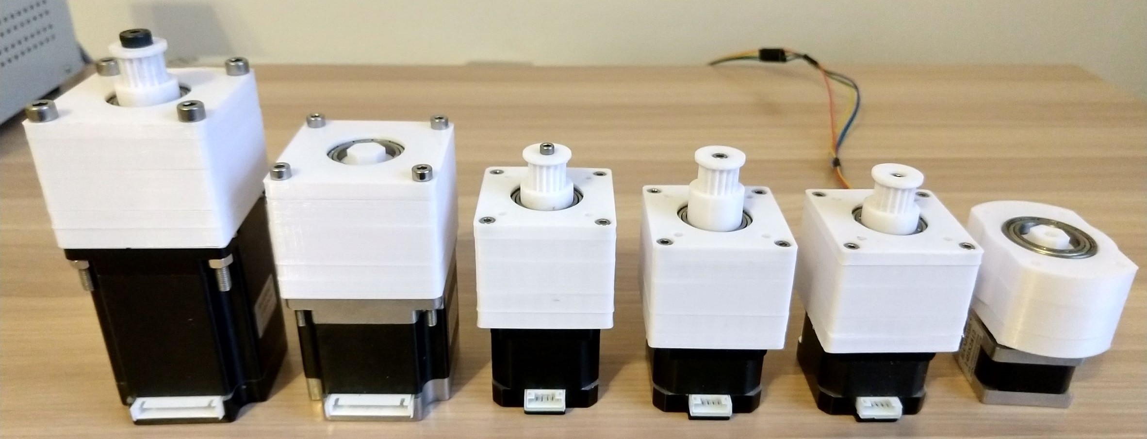
The initial release of this robot arm used stepper motors to directly drive toothed belts at the joints. In this first revision, 3D printed
planetary spur-gear reducers (see image above) have been added to all joints to increase joint torque output. Additionally, all the toothed drive belts are now
HTD-3M, and all pulleys and idlers are 3D printed. The following
table summarises the robot arm's links and actuators.
| Joint |
Driven link |
Motor |
Motor holding torque |
Planetary gear reduction |
Belt drive reduction |
Total reduction |
|
1 |
Shoulder |
Nema 17-40 |
0.4 |
4.5 |
6 |
27 |
|
2 |
Upper arm |
Nema 23-76 |
1.9 |
4 |
5 |
20 |
|
3 |
Elbow |
Nema 23-57 |
1.3 |
4 |
5 |
20 |
|
4 |
Lower arm |
Nema 17-34 |
0.13 |
4.5 |
4 |
18 |
|
5 |
Wrist |
Nema 17-34 |
0.28 |
4.5 |
4 |
18 |
|
6 |
Gripper |
Nema 14-28 |
0.28 |
5 |
n/a |
5 |
|
7 |
Gripper fingers |
MG996R |
0.15 |
n/a |
n/a |
0 |
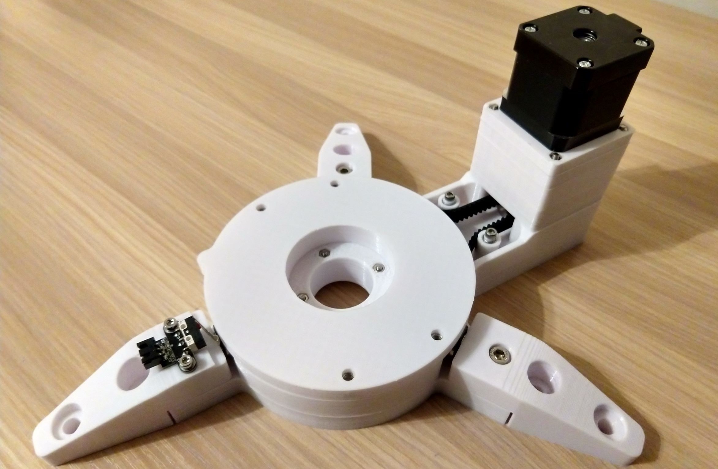
At
the base link (see image above), a Nema 17-40 stepper with a planetary gear reducer actuates a belt driving a pulley fixed to the bottom of the shoulder link (joint
1), adding a further speed reduction. The radial load at the belt driven pulley is taken by a radial
bearing secured to the base link. The axial load of the shoulder link
is taken by three small bearings fixed to the base link, on which the
shoulder link rolls as it rotates. Extending outward from
the base link are three feet to provide additional stability, and
which are also used to secure the robot arm to a stationary base
(I use a wooden board clamped to a desk). At the robot arm joints, toothed
belts are generally tensioned using 3D printed idlers rotating on bearings, and
radial bearings are used to take the load at the joints (mostly radial loads, joints 4 and 6 also have small axial loads) .
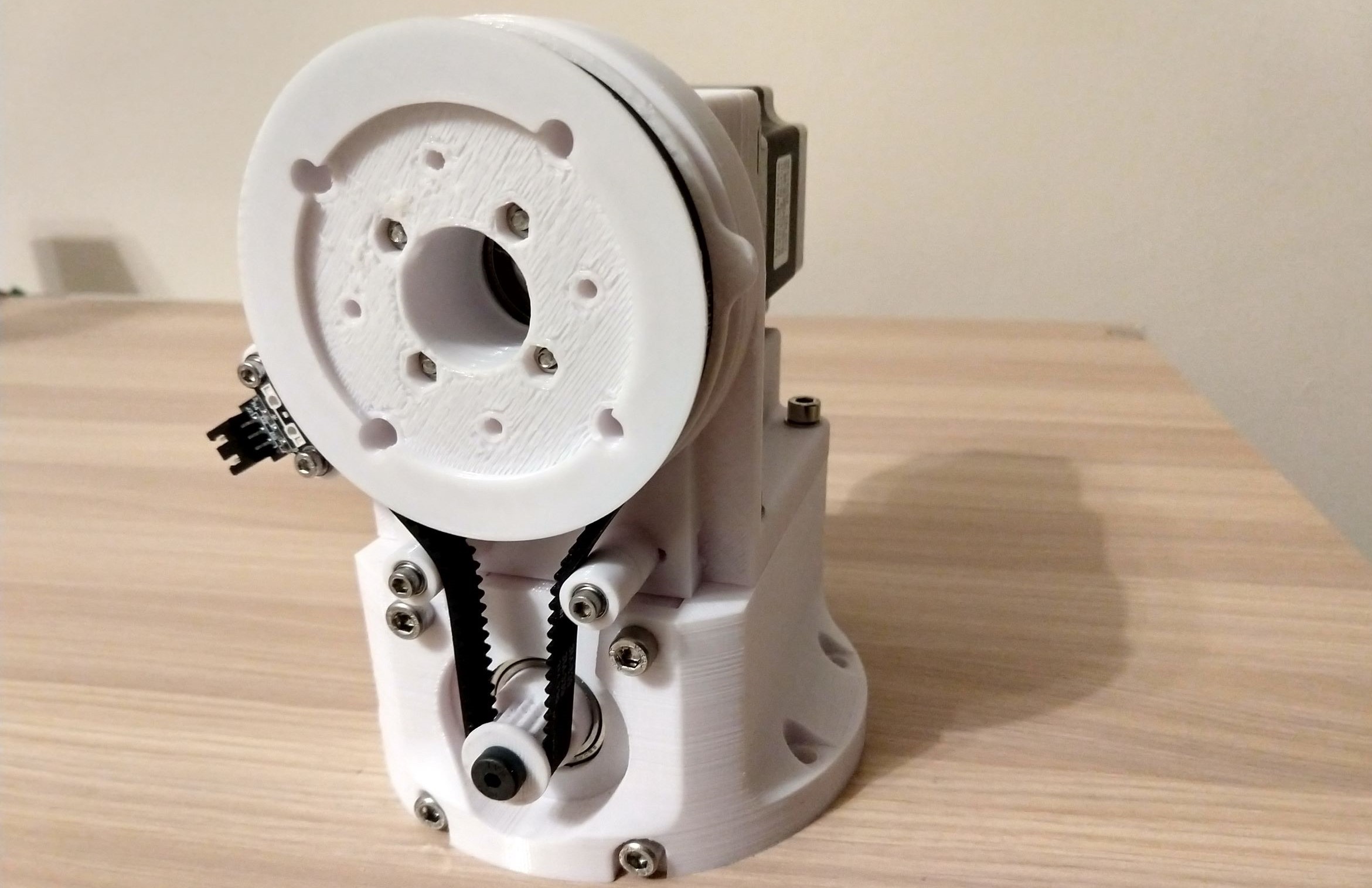
The shoulder link (see image above) holds the two Nema 23 steppers, each fixed to its own bracket, one placed on top of the other. The lower stepper (Nema 23-76) with a planetary gear reducer actuates a belt driving a pulley fixed to the upper arm link (joint 2), adding further speed reduction. Passing through the axis of that driven pulley is a 3D printed shaft coupling the upper stepper (Nema 23-57, with its planetary gear reducer) to a drive pulley fixed to the upper arm link. Shoulder screws are used at the Nema 23 drive pulleys to support the high radial loads at the drive belts.
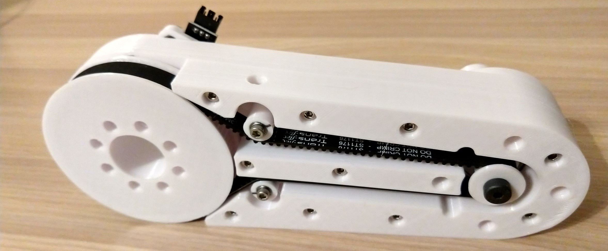
A belt extends across the upper arm link (see image above) between the drive pulley coupled to the...
Read more »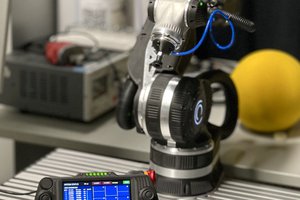
 Adrian Prinz
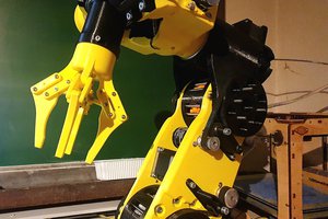
 Samuel Meurice
 Arcadia Labs
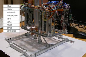
 Sergei V. Bogdanov