0%
0%
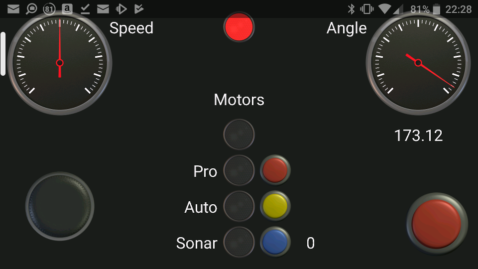
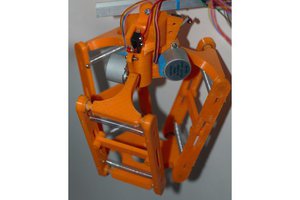
Android Controlled Self Balancing Robot
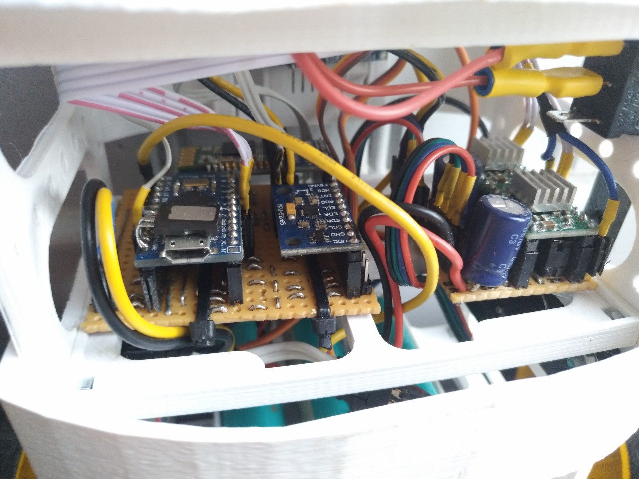
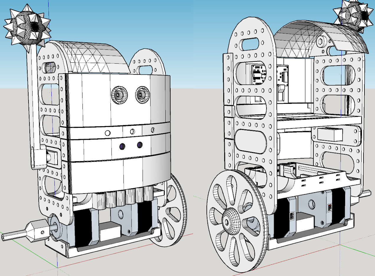
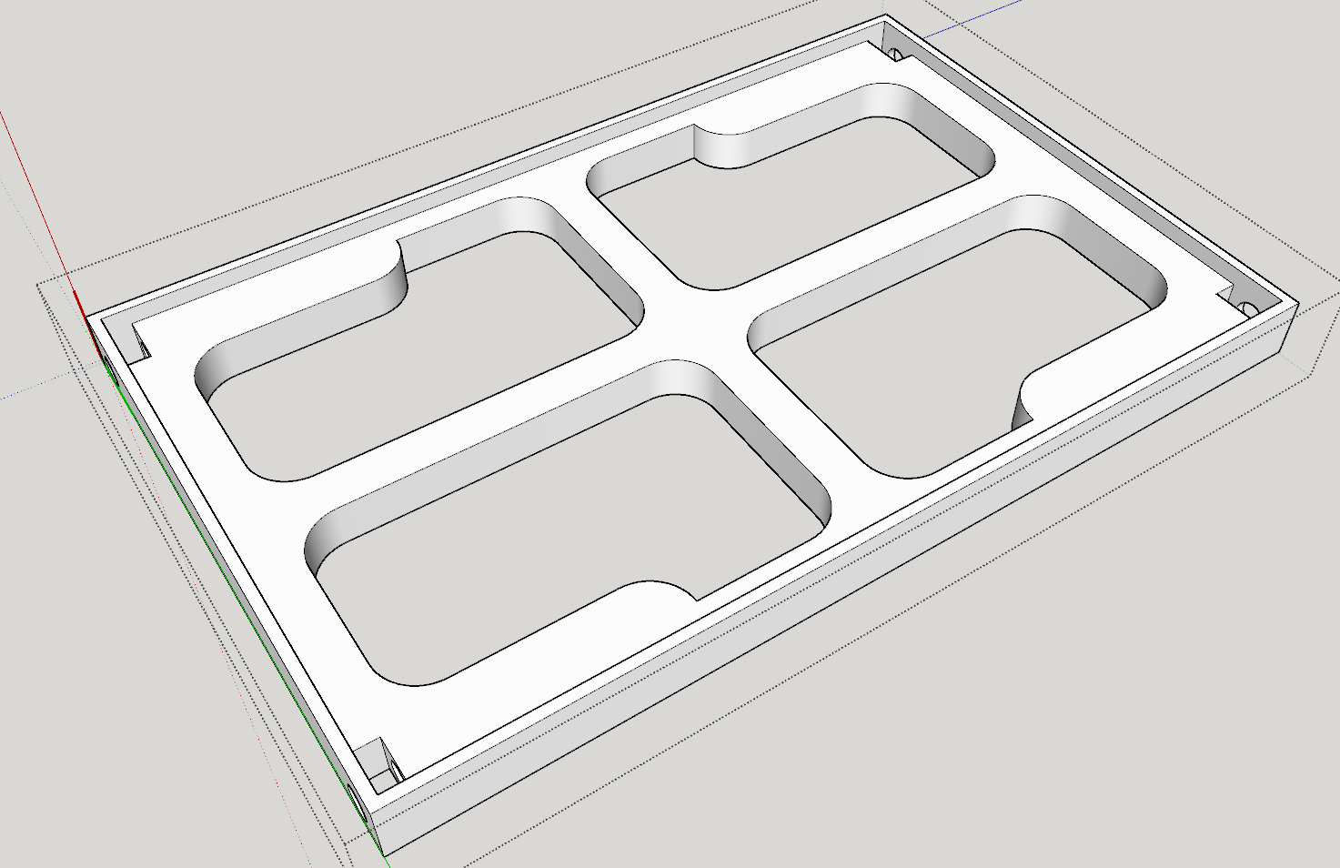
A smartphone controlled balancing robot using bluetooth, stepper motors, homemade electronics and 3D designed / printed parts.
 Arcadia Labs
Become a Hackaday.io member
Already have an account? Log in.
Just one more thing
To make the experience fit your profile, pick a username and tell us what interests you.
Pick an awesome username
hackaday.io/
Your profile's URL: hackaday.io/username. Max 25 alphanumeric characters.
Pick a few interests
Projects that share your interests
People that share your interests
 Tinkers Projects
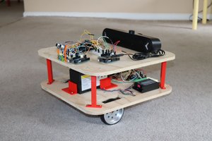
 Mike Rigsby
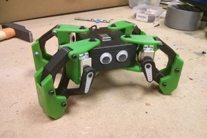
 Javier Isabel
 BINGOBRICKS