 Stuart MacKenzie
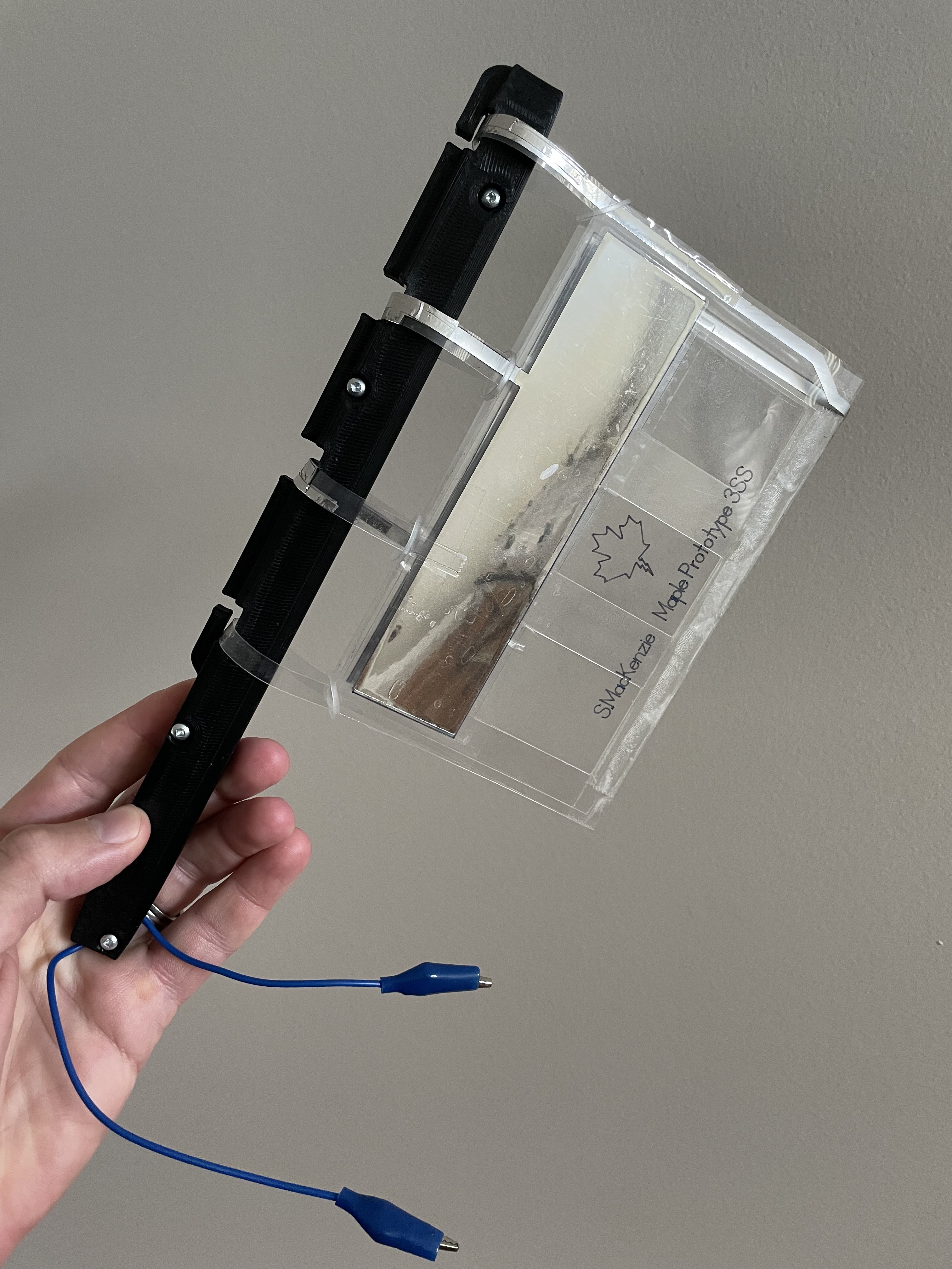
A FLAG is one of the first thin film technologies successfully prototyped for outdoor wind power. It is essentially a self-actuated-air-valve made of thin plastic film, combined with an electrostatic machine. This simple, lightweight, inexpensive, easily manufactured, and recyclable technology is a new way to generate small scale electricity. FLAGs can have the appearance of flags, or leaves, and are light enough for airborne wind power.
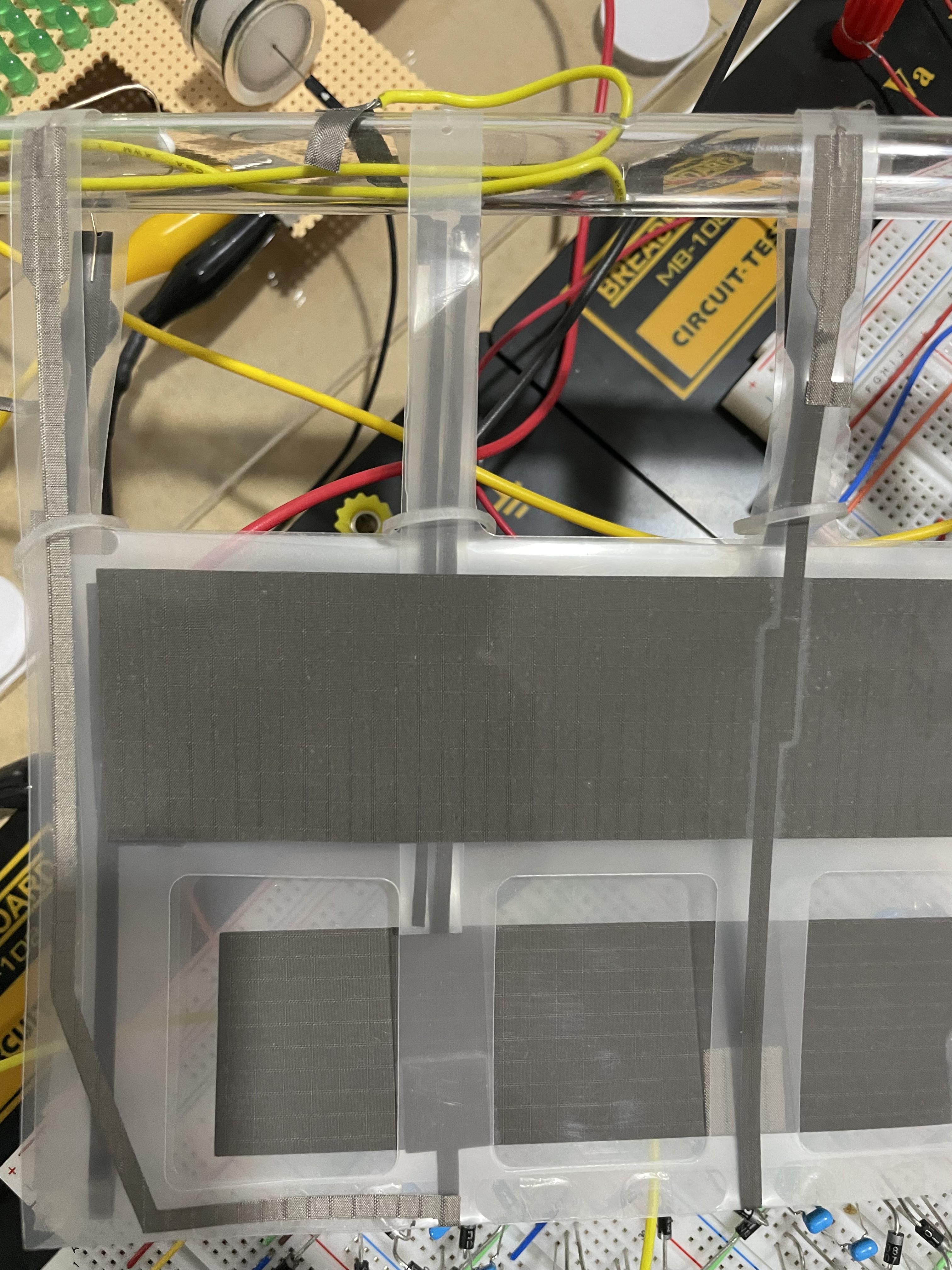
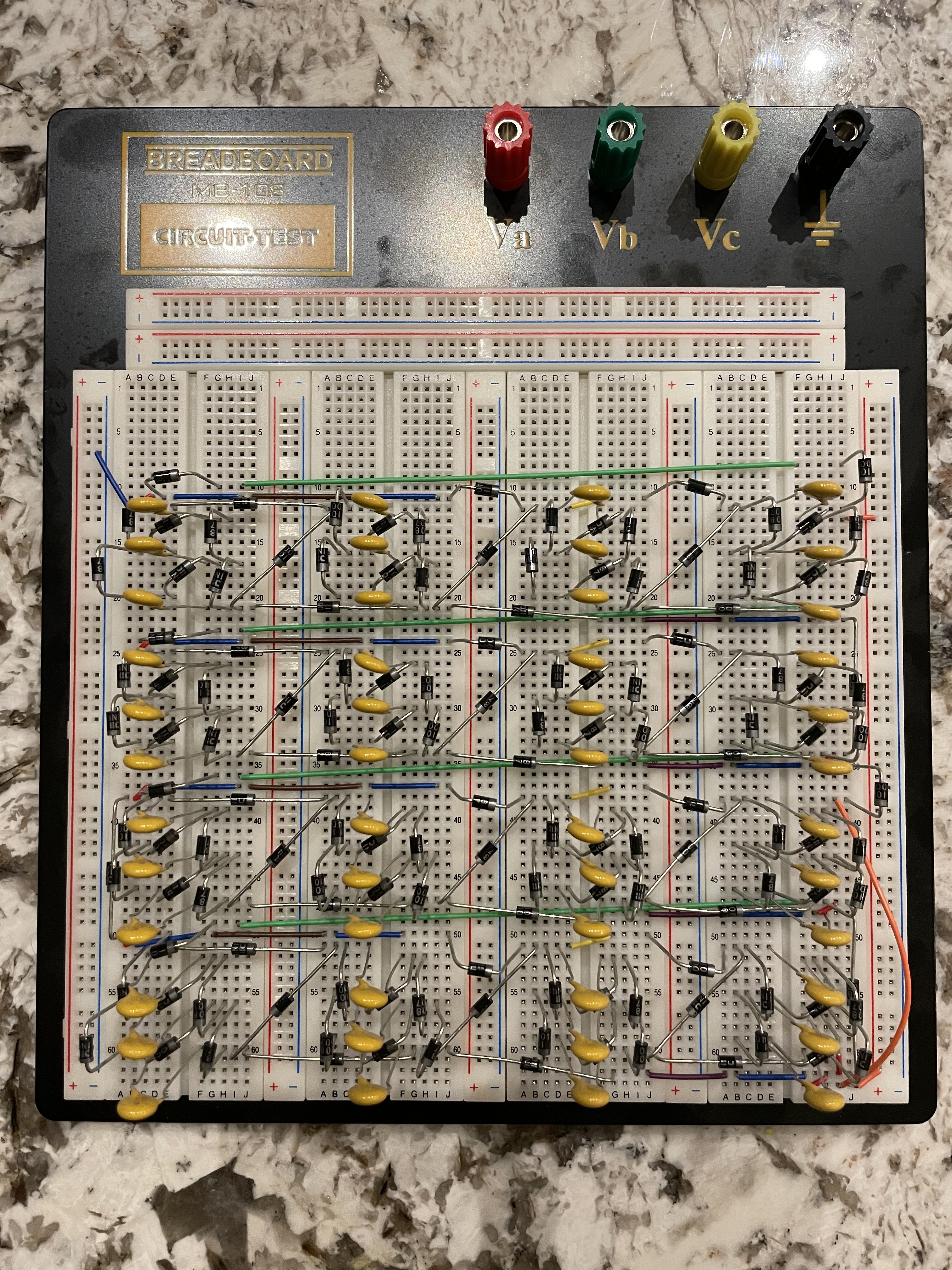
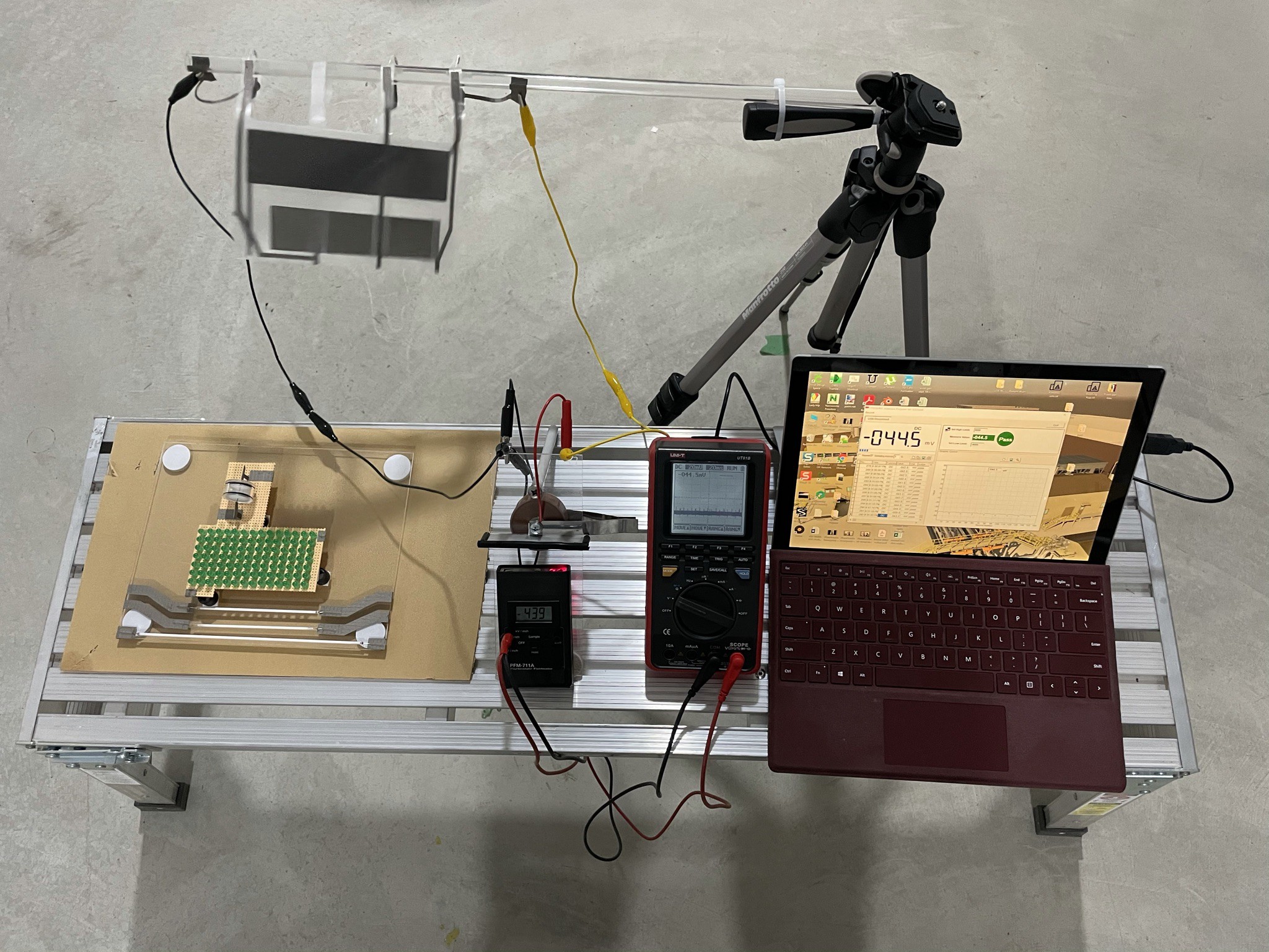
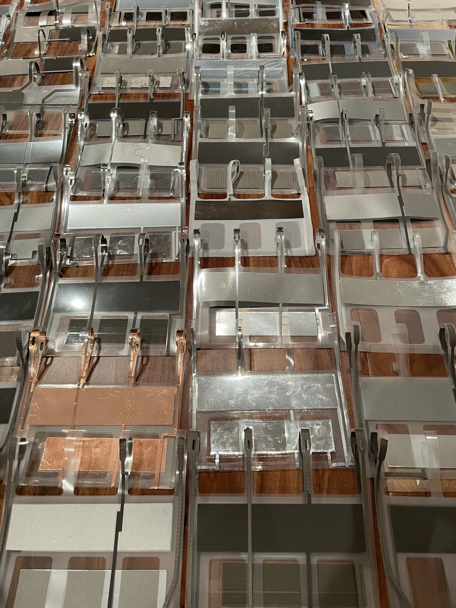
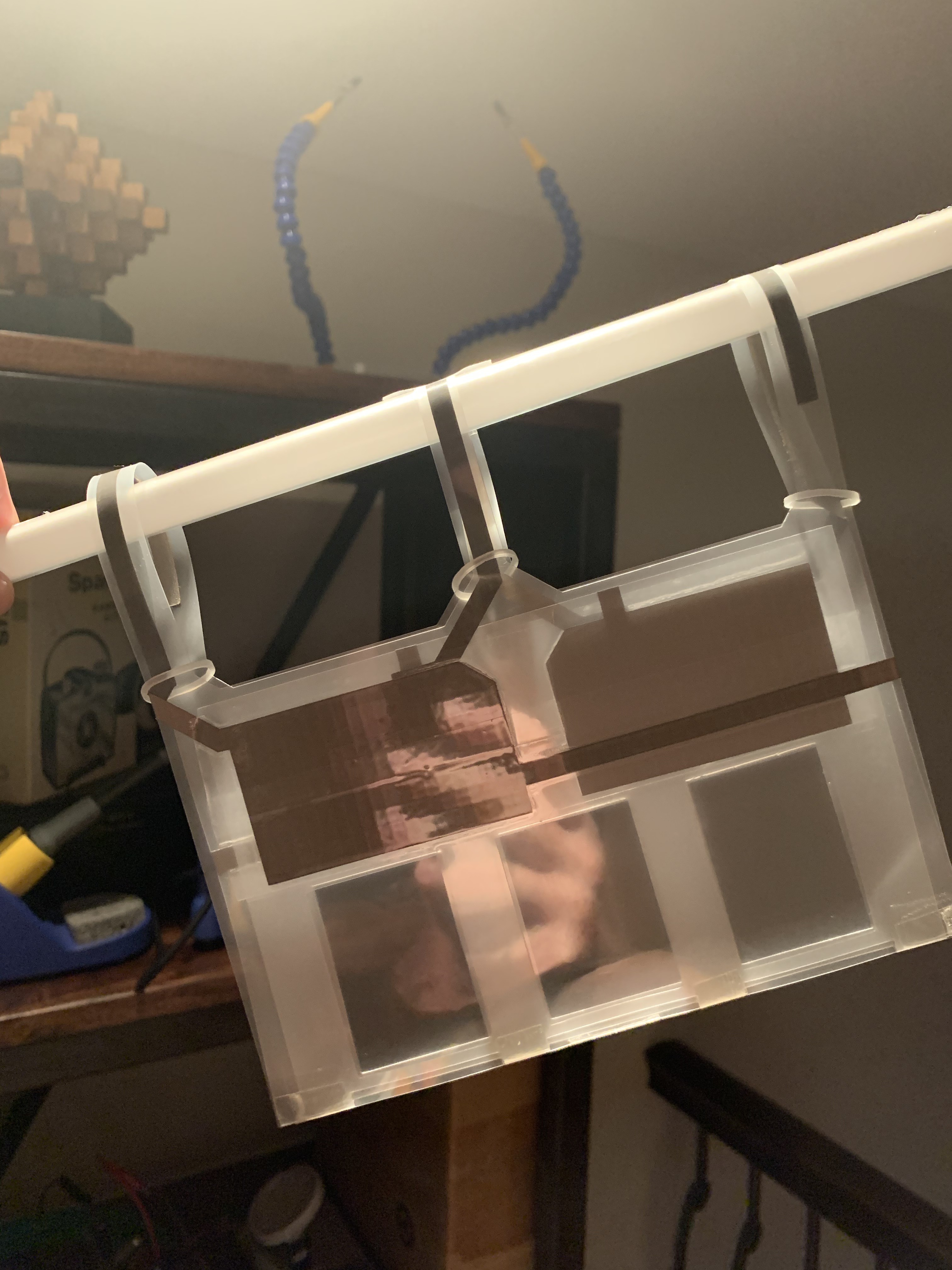
The generator is surfaced with conductive areas called "sectors", that generally act as variable capacitors. Either mechanical contact switches, or diodes are also used to strategically transfer charges between sectors, so that the mechanical work of pulling the oppositely charged sectors apart can generate electricity. A number of different harvesting circuits have been successfully prototyped in combination with the aerodynamic oscillator. This particular FLAG build uses diodes, and the circuit used is depicted below.
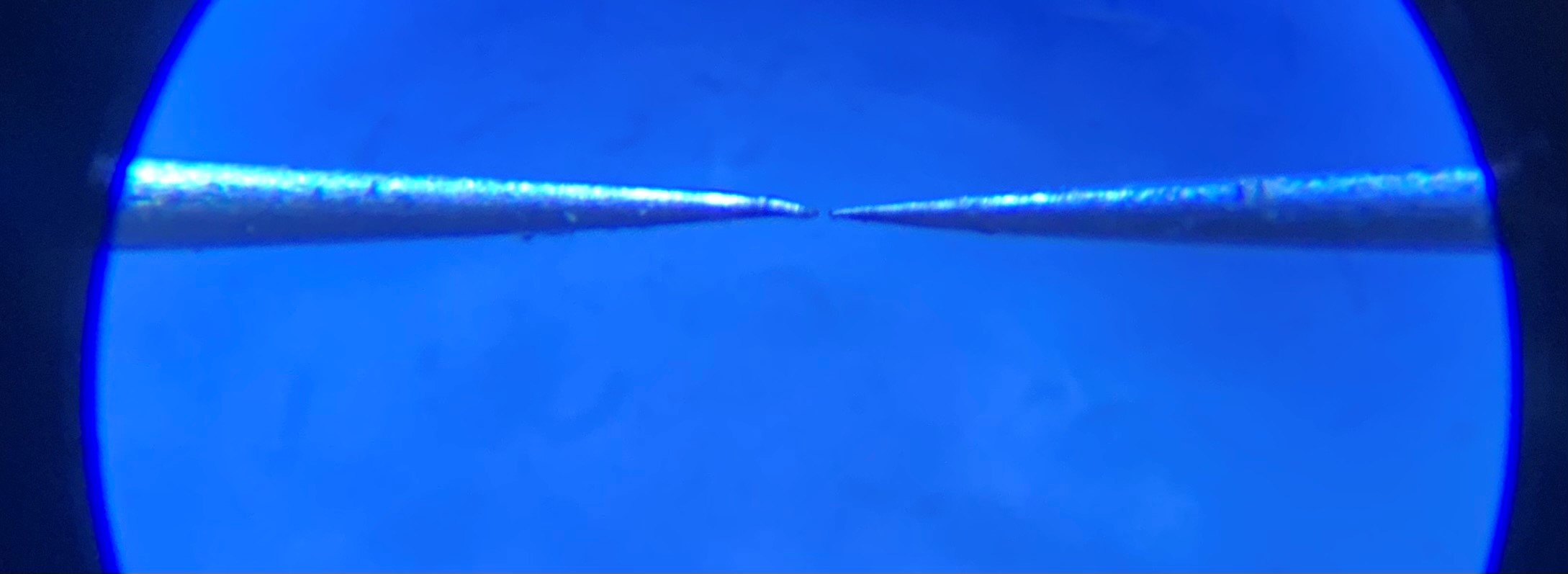
C1 is essentially a variable capacitor consisting of three sectors, each mounted onto one of three layers of the polyester film. The inner sector can move back and forth between the other two, and the charge on C1 is increased by a factor of 2 each reciprocation (if connected to ground). This design is not connected to ground for ease of construction, so the factor is likely reduced to 1.6. C2 is an energy storage capacitor, which is not absolutely necessary but improves the reliability of the machine and size of the output current pulses. The circuit is similar to one described in De Queiroz, A. C. M. (2016). Energy harvesting using symmetrical electrostatic generators. 2016 IEEE International Symposium on Circuits and Systems (ISCAS). doi:10.1109/iscas.2016.752732, except this circuit uses the equivalent of a three plate variable capacitor, instead of two synchronized variable capacitors, and there is no true ground connection. Elimination of the ground connection simplifies the construction, and electrically likely causes that part of the circuit to "bounce" in polarity as the generator runs. The lack of a ground connection should have an impact on performance, but the impact has not been obvious in testing.
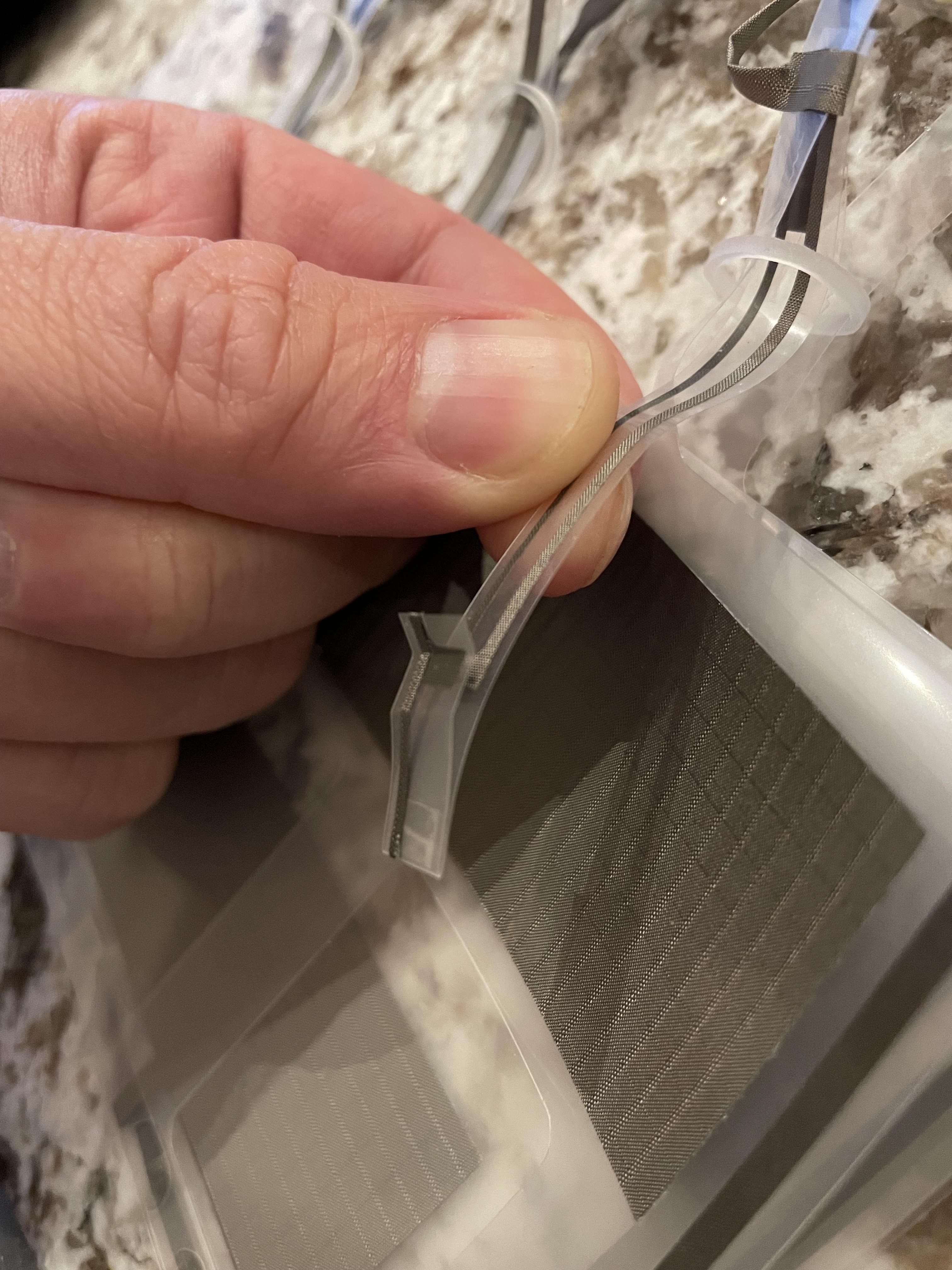
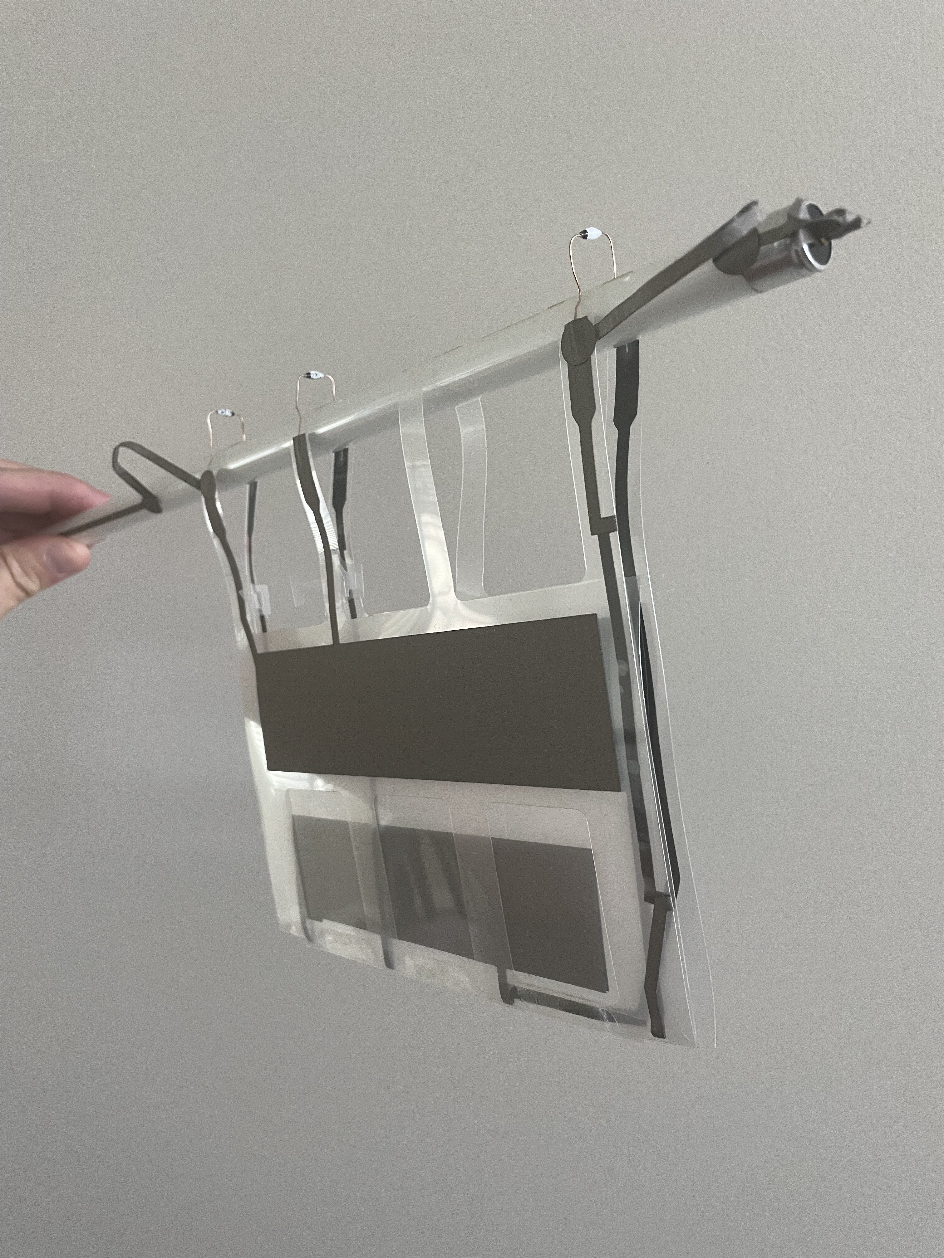
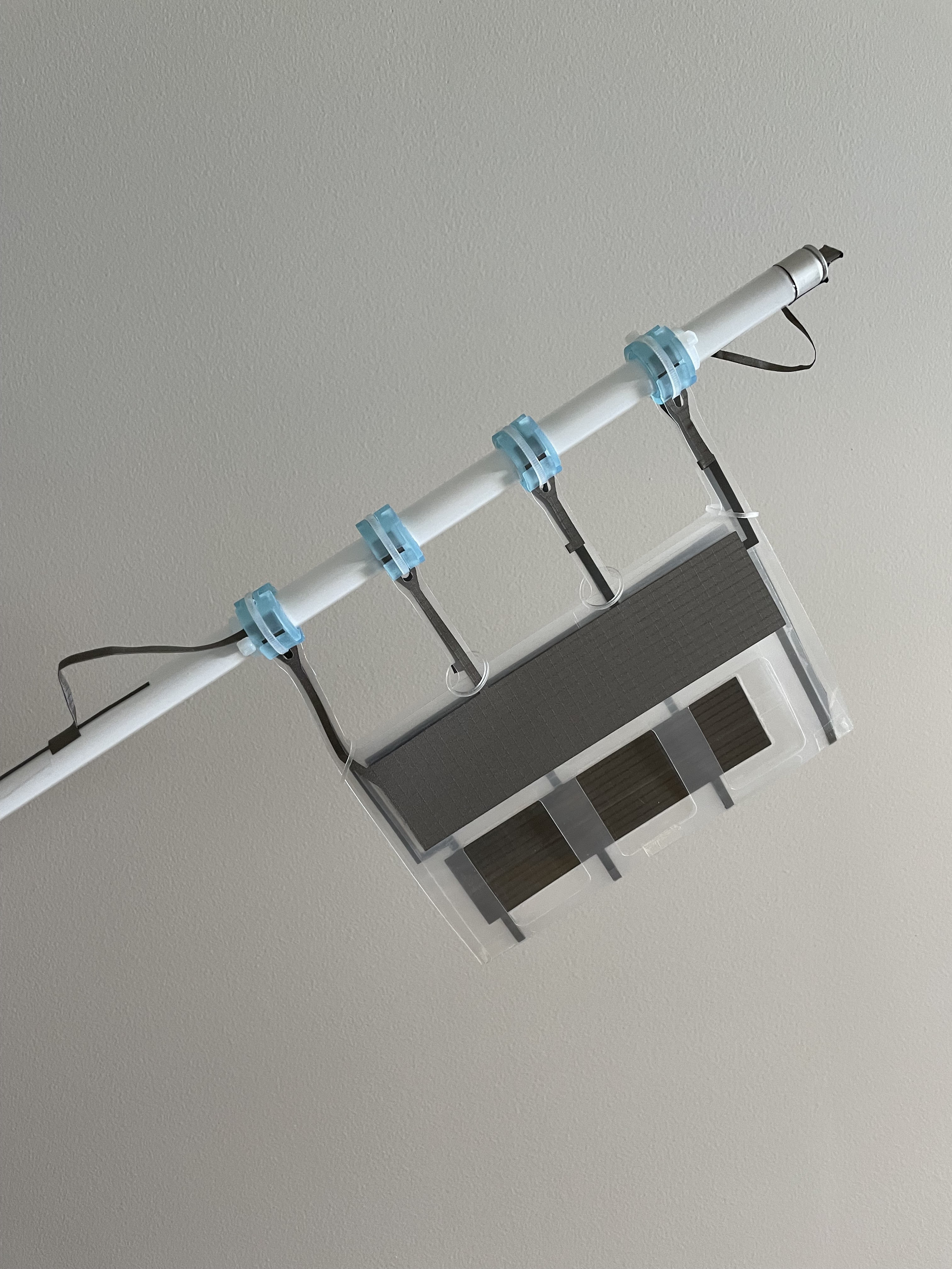
The generator is made of one piece of polyester film, cut and folded into three layers. The outer layers have holes which cause the inner layer to oscillate in the wind. The inner layer of film blocks one set of holes, causing air to flow through the opposite set of holes, which "sucks" the inner film to the opposite side, blocking the opposite set of holes. This ultimately creates a very stable and repeatable oscillation over a wide range of windspeeds.
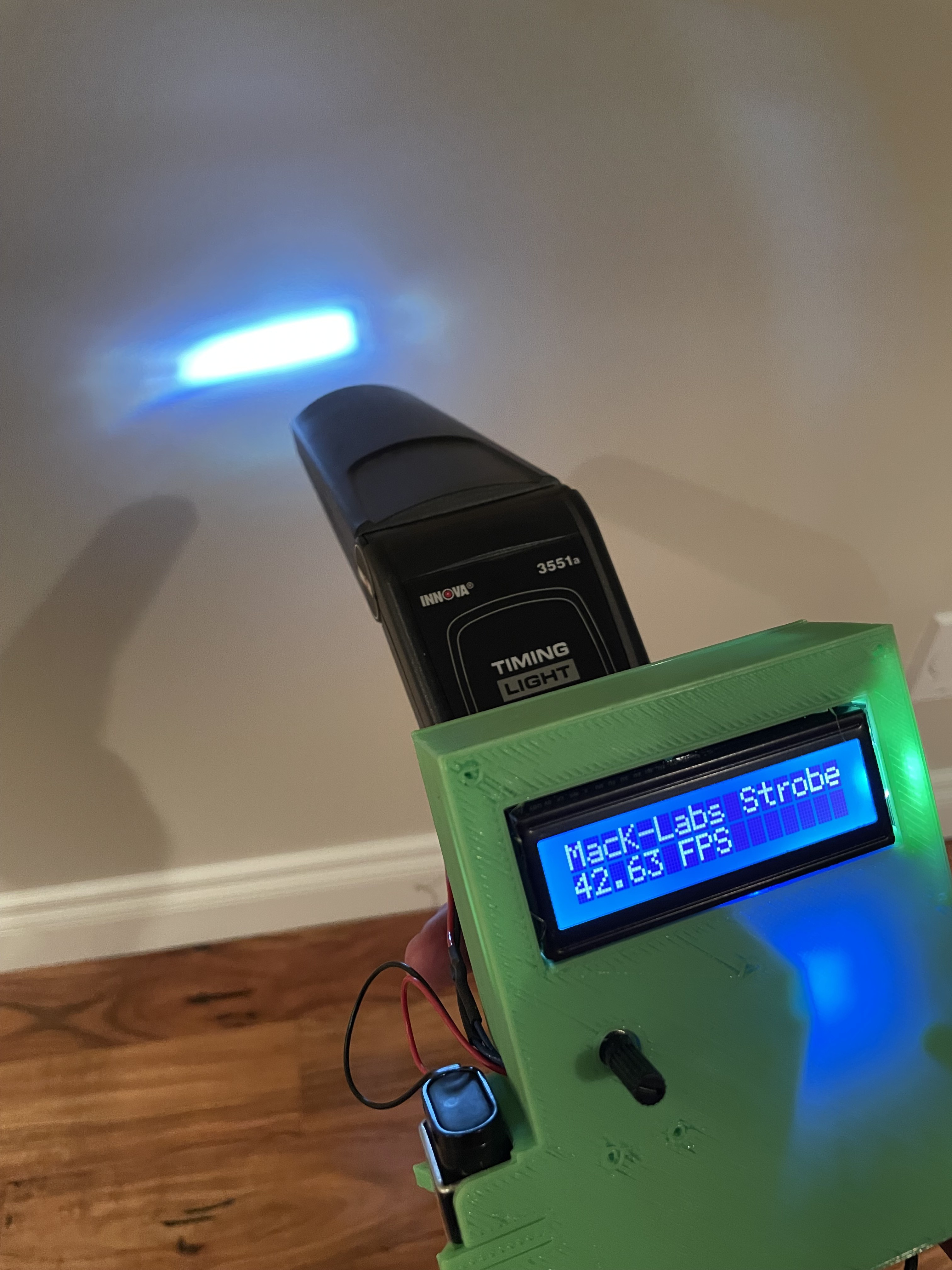
The FLAG prototypes operate at windspeeds in the approximate range of 15-50 km/h. The thinner films are lighter, and have a lower cut-in speed, but theoretically cannot operate at as high of voltages. At 20 km/h, the oscillating frequency is in the range of 10 Hz.
Since the conductive surfaces are open-to-air, the output is affected by humidity. The generator is self-starting and works well up to 60% humidity, depending on the materials used. At low humidity they have run at up to 2 kV (occasionally causing breakdown of the polyester film). Higher operating voltages result in significantly higher power outputs, so future improvements should include fully enclosing the conductors in polyester.
The two other thin film technologies that have been attempted for wind power applications are piezoelectric films, and TENG (triboelectric nano generators). FLAG has some advantages over these technologies including the use of non-specialty materials, low cost, and relative insensitivity to humidity.
NOTES TO HACKERS/MAKERS:
● Recently, the circuits needed to cheaply and efficiently convert pulses of high-voltage-low-current to more useful voltages have been...
Read more »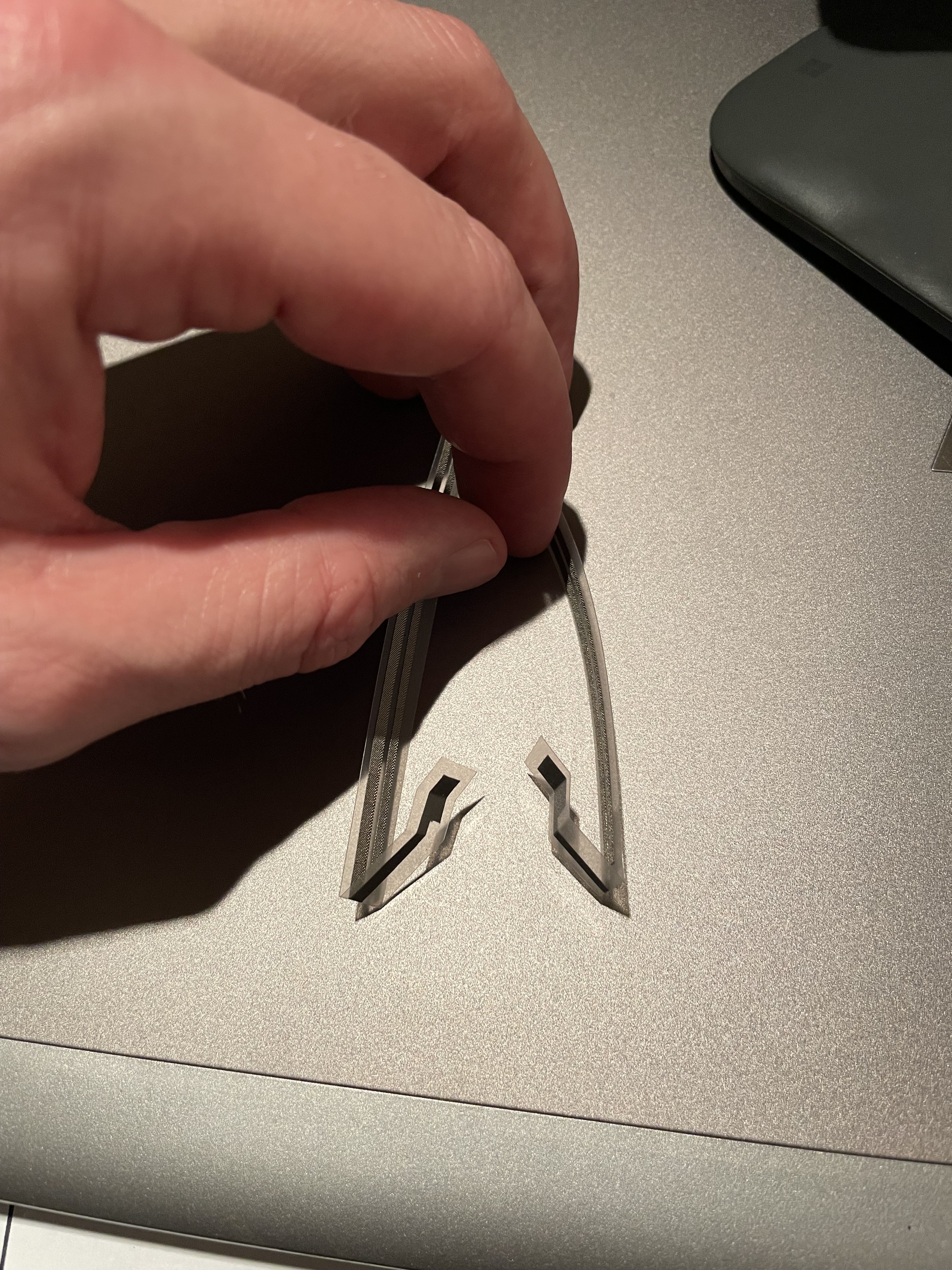


 SUF
SUF
 matseng
 Lucy Fauth
 nrrdzilla
Cricut is a versatile piece of machinery, and one of its coolest features is its Adaptive Tool System. This feature allows the Cricut machine to cut different materials from side to side, move up and down, and lift and turn. It makes the whole craft-making process less troublesome for crafters. This tool system allows you to use various blades and tools to create different types of projects. You can create a design using the images and fonts in the Design Space app’s library. The app is compatible with every Cricut machine and is free on Visit site: design.cricut.com/setup