Science3D
The Expected features
While thinking about this project, I came up with a list of features that I would like to have while creating this design. This is the list:
- The most important feature is to post the print status on the cloud, as an IOT device, so I can monitor the print status from a distance
- A web interface to see the print status... just a growing graph would be enough for me
- One or more LEDs to display the detected activity
- One LED to show the Wifi connection status
- A buzzer that alarms if there is a problem
- A way to pause the printer if anything goes wrong
- The device should work on a small USB power supply
Circuit details
The circuit used a hand made "rotary encoder": my goal was to, initially, detect not only that the filament was moving but also to detect the direction. I noticed that the retract action of the printer pushed the filament up but, because I converted my printer to a direct drive, I do not have a Bowden tube anymore and this retraction movement do no more push the filament back into the spool.
Anyways, I kept the idea of a rotary encoder and used 2 LEDs and 2 photo resistors to evaluate the rotation. the circuit that is displayed here shows the 2 "Channels"; one for each LED-Photoresistor pair
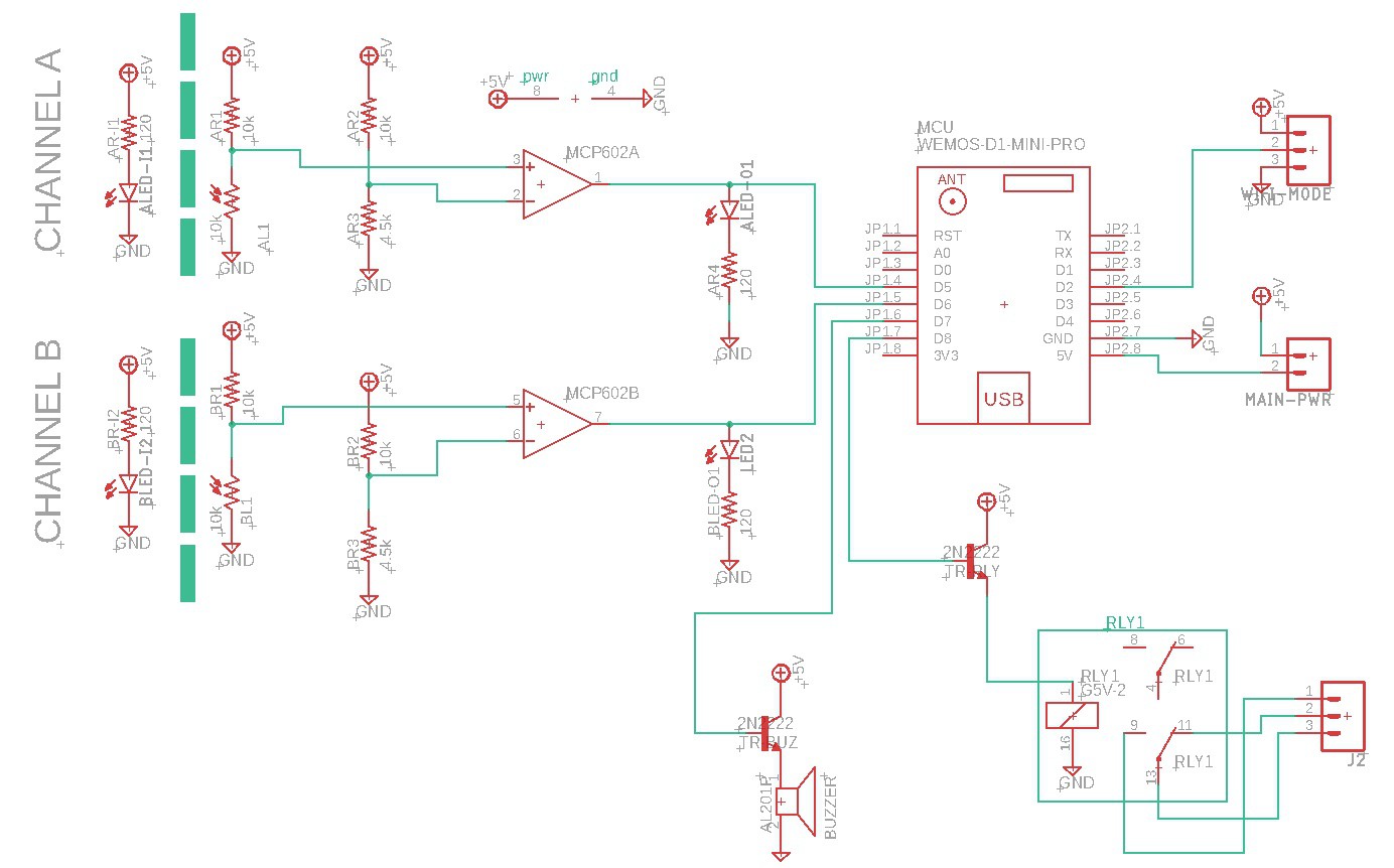
As we can see in the circuit, the two channels are driven by the two op amps that are included into the MCP602A chip. The goal of these channels is to flip a bit so I can read it from a digital pin.
Circuit explanation
When the light hits one of the photo resistor, the op amp compares the voltage divider, created by the photo resistor and the 10K resistor with the other voltage divider created by the 10k and the 4.5k resistors and when it goes over the threshold, it flips the bit and the values are read bye the pins D5 and D6 of the Wemos.
Then, internally, as soon as D5 or D6 changes, a counter is reset and as soon as it is greater than a predefined value (controlled by the web page) (50 second or so), the buzzer is fired and a relay is triggered triggering the PAUSE action on the printer.
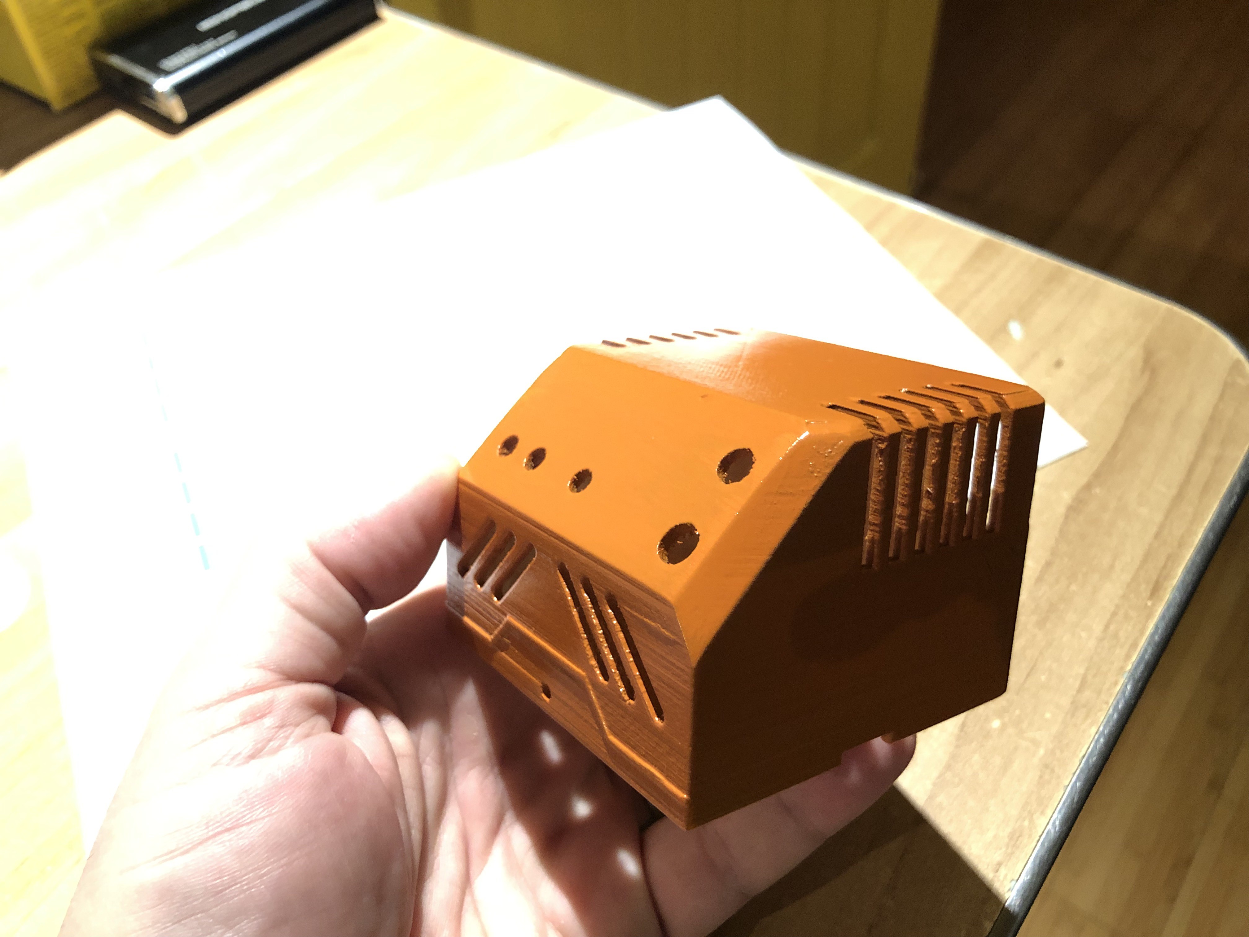
The Enclosure
I like the "old school" or "retro" designs so, I designed an enclosure that reminds me of this era.
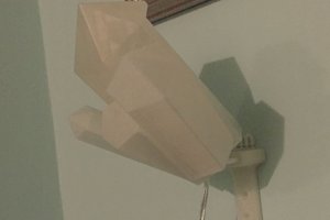
The Detector
The small circuits were cut with my CNC. They are different:
- one of them include 2 LEDS and 2 Wires connect to the board ( 5v and ground )
- the other board include 2 photo resistor and 3 wires are needed: 1 ground, 1 pin for the first photo resistor and the other pin for the second photo resistor

1 / 2
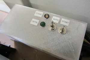
The board
The board is compose of 3 parts:
- The largest part contain the main circuit
- The 2 other parts are for the 2 sections of the Rotary Encoder

1 / 2
The web activity
While printing, I can take a look at the print by checking the graph.

While printing, the value on the graph grows. The previous image shows a print that started than crashed because I stopped the spool from turning. I replace the spool, reset the Wemos and restarted the print and that's why the graph looks like this.
The web interface allows me to change the buzzer and relay reaction delay.
I also added a "Raw" section where I see the data entry and the related date-time for each entry which keeps me informed.

Video - Look at the project, in great details
 TheGrim
 0n37w0
 Bits4Bots