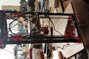
The Monoprice Select Mini is a great 'first' 3D printer, especially for those who are unsure if this hobby is right for them, as well as for those who want a machine that is 'plug-and-play'. However, many users find that they quickly reach the thresholds of the machine's capabilities due to the small build size, low power, etc. I pushed the capabilities of the printer before finally adding several modifications due in part to design flaws (such as the damaged bed wiring), as well as to improve the capability of the machine (such as a printed extruder body to print flexibles, and an all metal hotend). I am sad to say that the introduction of a new, larger and more capable 3D printer resulted in the MPSM being sidelined. even after these upgrades.
There are numerous replacement X-carriages available such as US Water Rocket's modifications for the MPSM V1: https://hackaday.io/project/14823/logs, but the majority of the designs seem to be built around a single toolhead, typically an E3D V6 hotend. Some designs use the build-in M3 through holes for mounting, but this solution is not stable enough for my needs. The replacement of the stock carriage is not a complicated process, but further upgrades to the carriage and/or toolhead are limited after the replacement due to the integration of the carriage and toolhead mounting solution.
The objective of the modification outlined in this project is to allow users to expand the capabilities of this machine by providing secure mounting of toolheads and various add-ons without complete disassembly of the machine for each variation. The Monoprice Select Mini can become a test bench for various hotends, extruders, etc. and breath new life into the machine that may have been tucked in the corner.
Files can be found on Thingiverse: https://www.thingiverse.com/thing:5158484
Special thanks to Kadah for the excellent CAD model of the MPSM V2. This model helped ensure that the design's dimensions would work with the printer, while minimizing the need for trial and error.
KAdah's model of the MPSM V2 can be found here: https://www.thingiverse.com/thing:2681912
Please enjoy the project, and feel free to ask questions.
Cheers
January 11, 2022: Update: I've used this modular toolhead to convert my MPSM V2 to a direct drive extruder that uses 2.85/3.00mm filament
https://hackaday.io/project/183470-mpsm-v2-direct-drive-for-285300mm-filament


 mmiscool
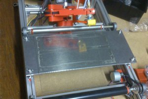
 invent2main
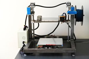
 Fred
Fred
 Swaleh Owais
Love this idea, especially with how cheap you can get a used MP Mini these days. I actually came up with a similar tool holder for the PrintrBot Play, but by comparison its a much rarer machine.