 Sayantan
Features of the Circuit:
1.Two modes of operation, turntable mode and shaking mode, any one to be used at a time.
2.Manual speed control for both modes.
3.For turntable mode, clockwise and anticlockwise modes are there, any one to be used at a time.
4.For shaking mode, the to and fro motion time can be controlled manually
In the following steps, we will learn the circuit from schematic to implemenation.
0%
0%
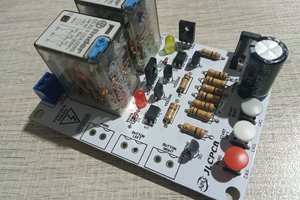
A 555 Timer based Turntable and PCB Shaker Circuit
555 timer with a motor driver to make a rotary turntable driver and a PCB shaker to etch PCBs, in a single circuit .
Become a Hackaday.io member
Already have an account? Log in.
Just one more thing
To make the experience fit your profile, pick a username and tell us what interests you.
Pick an awesome username
hackaday.io/
Your profile's URL: hackaday.io/username. Max 25 alphanumeric characters.
Pick a few interests
Projects that share your interests
People that share your interests
 ElectronicABC
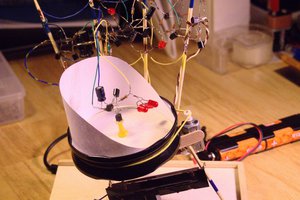
 bornach
 Chris
Chris 
 Sagar 001