 Emmanuel Herrera
Designing:
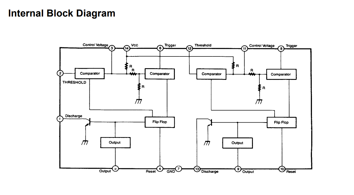
First, what would be the heart of the project was designed and assembled on a protoboard, with a double 555 (556).
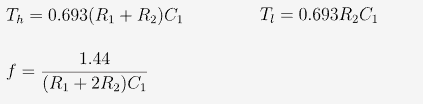
The two timers were used as monostable with an on time of approximately 1.65s. (R = 1.5MΩ C = 1µF)

A high value resistor and a "small" value capacitor are always better (besides being cheaper), timing accuracy is not crucial, so a simple electrolytic was used.

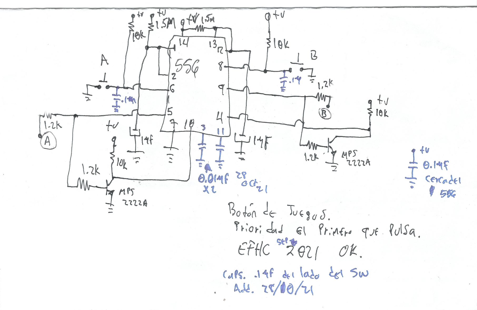
When one of the timers is triggered, it automatically inhibits the other from being able to trigger while it is active, (the output of the timer that is activated (5 or 9), is inverted by means of a general purpose transistor and a pair of resistors and inhibits to the other timer through its reset pin (10 or 4)) reason why a reset button is not required, as it does so automatically by passing the stipulated time. So with a very simple circuit, we already have most of the work.
By pressing one of the buttons, it will activate the corresponding timer output and will inhibit the other for the time we calculated above.
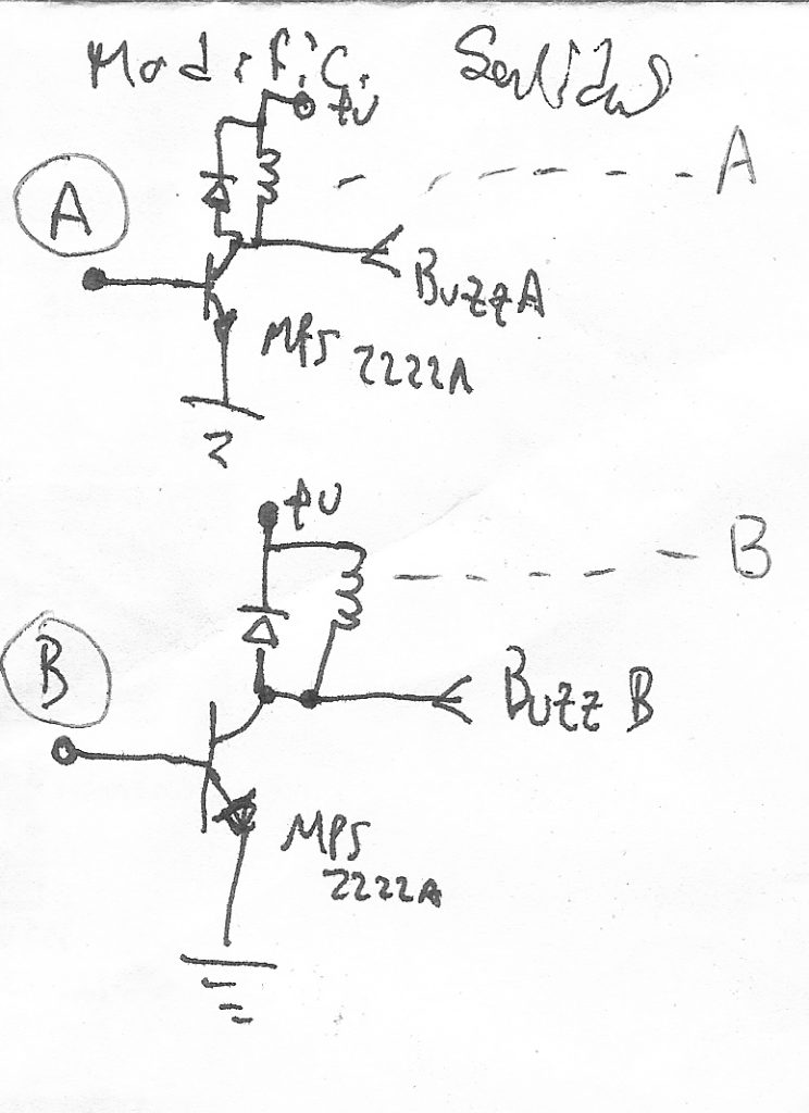
The outputs of each timer, besides to going to the transistor that inverts them to activate the reset of the other timer, went to a power stage built with an NPN darlington transistor TIP122 and activated the corresponding LED to the output, as we see in the diagram. Originally everything was thought for 12V, but later the power stage will change.

What if we add sound to it?
Despite the fact that the way it was it could be said that it fulfilled its mission, i thougt that when any output was activated, it would emit a sound simultaneously when the light corresponding to the button pressed was turned on. The first attempt was to add an active buzzer connected to + 12V, and a pair of diodes, connected with a common anode to the - of the buzzer and whose cathodes would go one to each output, with this we make a simple "or" with any of the outputs that is active, the buzzer will sound. While the circuit worked, the buzzers I had on hand were too loud and even annoying (3.5 kHz, 90 dB)
So that's why they weren't the right choice ... :(
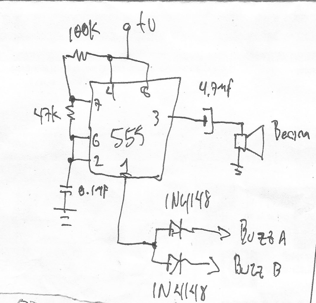
Let's make a tone generator out of a 555 then!
So a 555 was added as an astable with a Ra of 100kΩ, an Rb of 47kΩ, and C of 0.1µF. With these values, the high time is 10.19ms and the low one is 3.26ms, the frequency is approximately 74.23Hz.
The output was capacitively coupled to a miniature dynamic speaker used on PC motherboards.
The two diodes that make the «or» function were still used connected to pin 1 of the 555
Changing loads ...
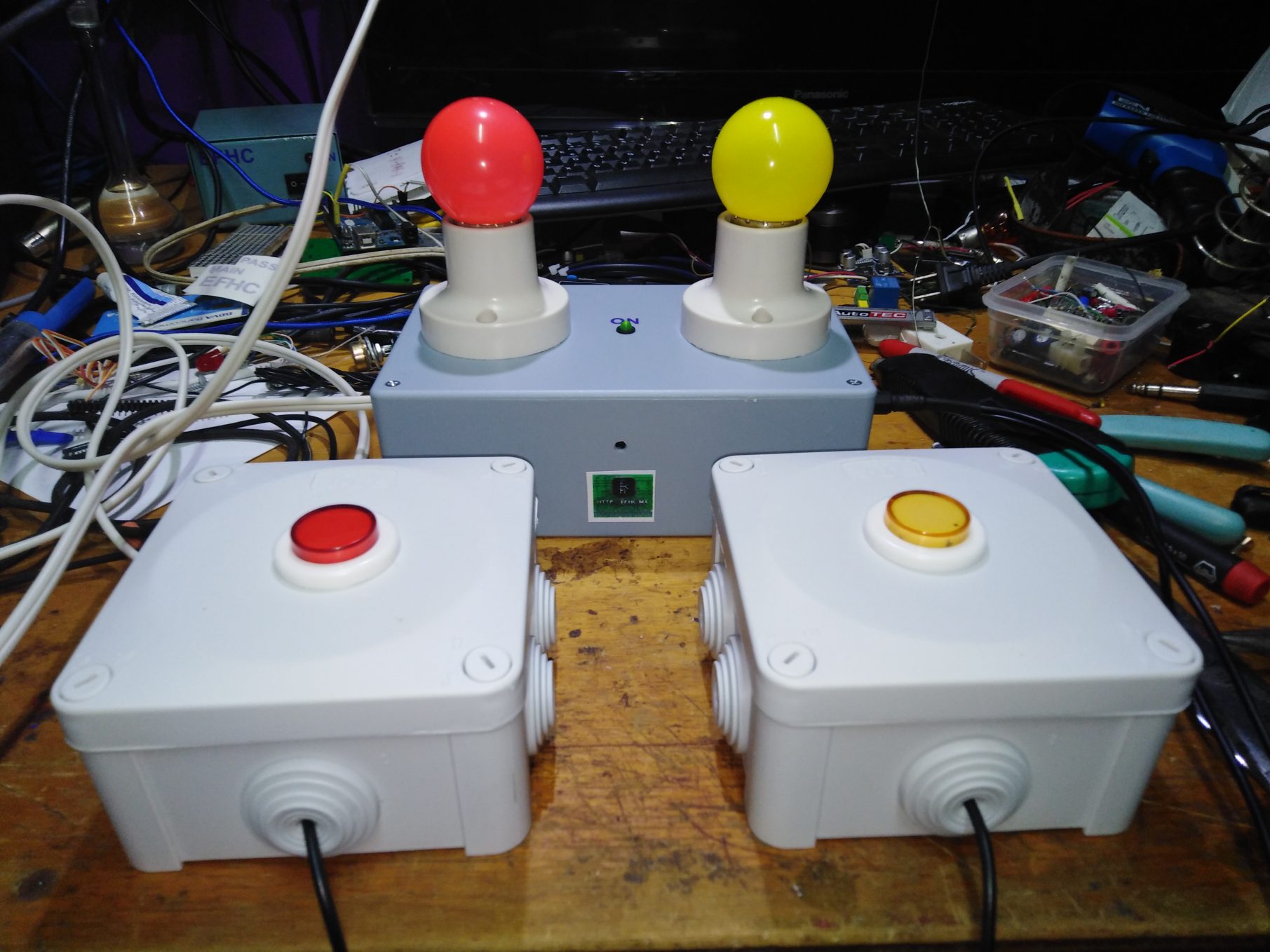
Then the story changed, because they asked me to use some colored LED bulbs that they had already bought, these bulbs already had their socket and even POT cable, but they were for 120VAC, so I adapted the power stage.
Removed the darlingons and LEDs from the first diagram shown, instead I used a pair of general-purpose transistors that drive two small relays (and the tone generator). These relays activate the lamp corresponding to the activated output.
As good practice dictates, each relay's coil have a reverse-biased 1N4148 diode to prevent the voltage induced in the coil when contracting the magnetic field could damage the transistor.
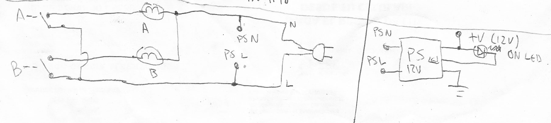
On the mains voltage's side, there is the AC input that comes from the plug, which feeds the two bulbs via the contacts of the relays switches and directly to the SMPS power supply that supplies 12V to the control circuit. The power supply PCB was removed from a commercial CCTV camera power supply. It is 12V 1A, more than enough.
Well now let´s put it together. The same type of universal perforated PCB was used for both models, and the same components.
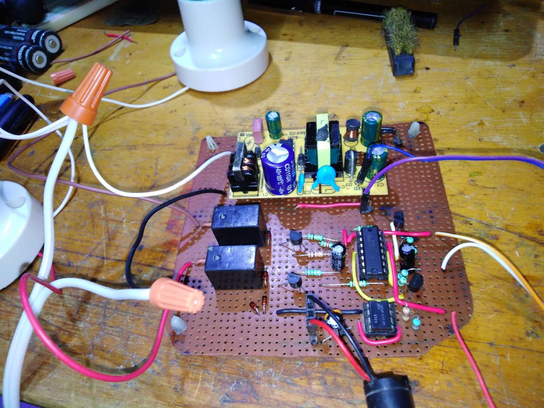
The circuit, sockets and bulbs were mounted in a project box.
The buttons were mounted separately in watertight boxes (on "model 1") and in button boxes (on "model 2") and were connected via a 3.5mm TRS plug and 2m of cable to the main box.

 Paul Stoffregen
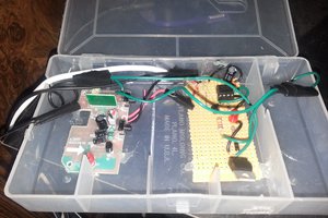
 Solderking
 mircemk
 Yann Guidon / YGDES