 mircemk
Tube amplifiers are highly respected by audiophiles for their distinctive sound as well as their esoteric appearance. However, their construction is relatively complex, especially in the part of power supply and output audio transformer. For these reasons, often are made so-called "Hybrid" audio Amplifiers in which the input preamplifier part is made with Tubes, and the output part is usually made with MOSFET transistors due to their high internal resistance, similar to Tubes. Thus the distortions of the even harmonics, which are in fact the reason for the colored warm sound of the Tube amplifiers, are amplified by the output transistor stage. But unfortunately these positive distortions occur most often in the output stage of the Tube amplifiers, so the aforementioned Hybrid amplifiers do not have very similar characteristics to the Tube amplifiers
The amplifier described in this project is also Hybrid but now the case is reversed and the Tube is used at the output, thus preserving all the positive features of a pure Tube Amplifier. Russian big power pentode (transmitter tube) GU81 is used at the output, which can still be easily bought in the countries of the former Eastern Block.
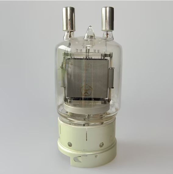
Supposedly this tube in this connection (SE) should bring 130 watts RMS as pure Class A. The circuit was presented by M. Anders in 2011, but I could not find any data on whether anyone made it and it works well. It is basically very simple and consists of components that we can have, or can be very easily found, with the exception of the output audio transformer. Luckily I had such a transformer taken of an old 50 watt Dynacord instrumental amplifier.

In order to simplify the project even more, I used some ready-made modules. In the following, I will describe in more detail the construction of this amplifier.
GU81 for heating uses 12 volts 10.5 Amps. For that purpose, the simplest way is to use cheap power supply from PC, and in my case it is power supply from old server PC. To extend the service life of the Tube, a series resistor of 2.2 Ohms / 10 Watts is used, which is bridged after twenty seconds from the moment of activation of the power supply. This avoids the shock of a sudden current impact.
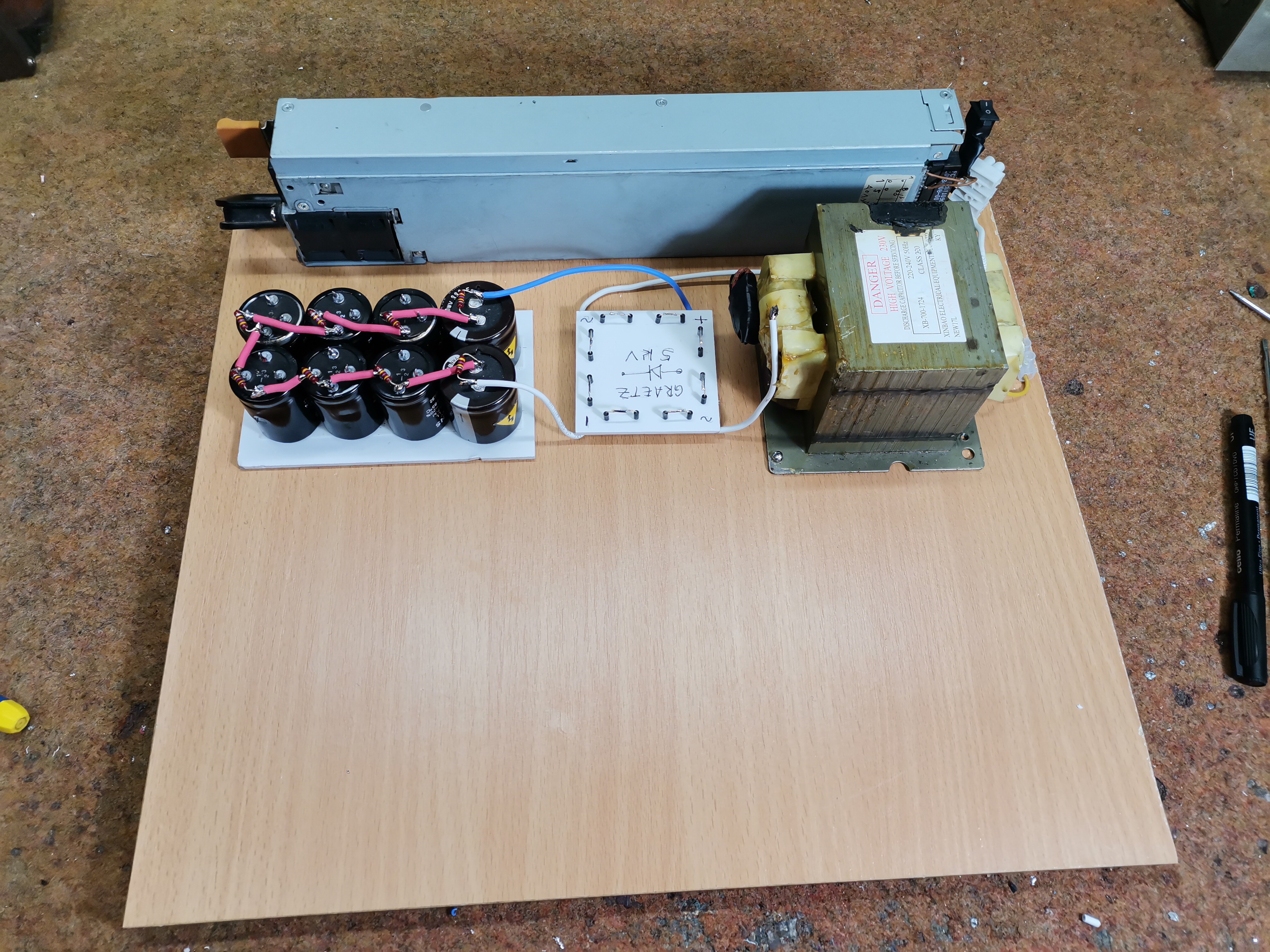
The next part is the anode power supply of Tube. For this purpose, a microwave oven transformer is used, which is relatively inexpensive and can be easily purchased at a service center.
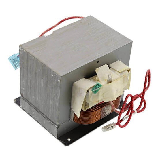
These transformers are not intended for long-term continuous operation, so it is desirable to use two such transformers to which both the primary and the secondary are connected in series, as shown on the circuit.
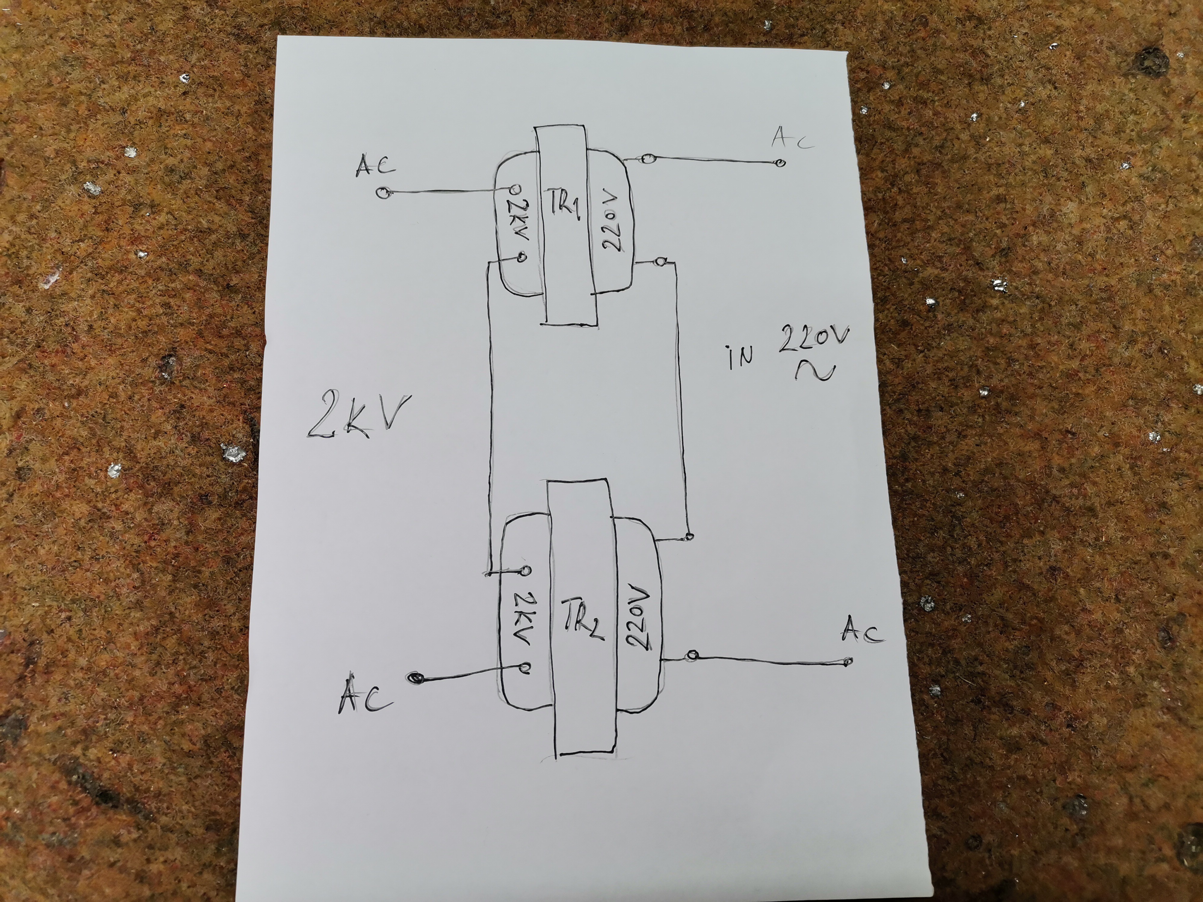
In both cases the output voltage is about 2.2 kilovolts. I use one transformer because I only use this amplifier during this presentation.
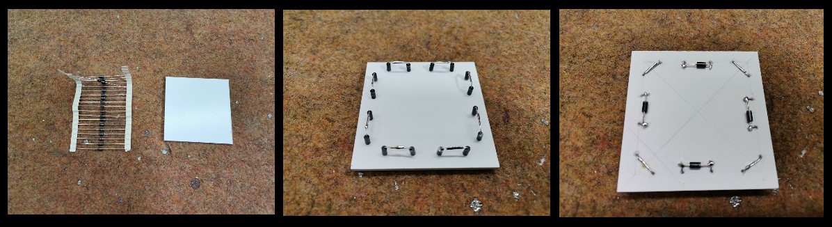
Follows the Graetz Bridge. Since it is very difficult to find such a component for very high voltage, I made it as follows:
Each branch of the Gertz Bridge consists of 5 series connected diodes of type 1n4007 so that the total breakdown voltage of the equivalent Diode is 5000V which is quite enough for this case.

Voltage filtering is performed with eight serially connected electrolytic capacitors for high voltage of 400 Volts, and on each capacitor is connected а parallel resistor of 470 Kohms, which are used to discharge capacitors after shutdown.
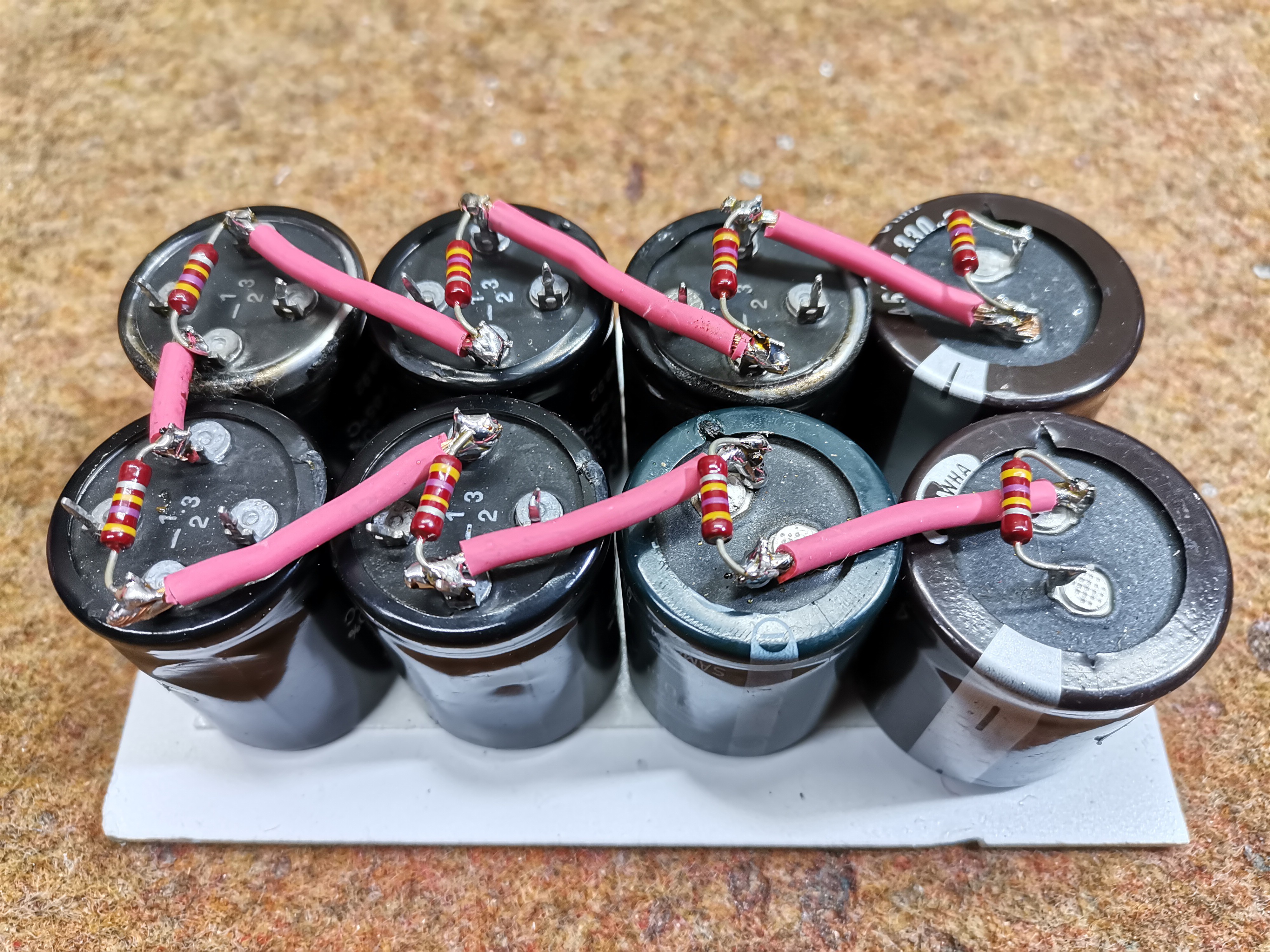
For better quality it is recomended that the total capacitance of these capacitors be higher to avoid noise. The power supply of the amplifier containing the transformers, capacitors and the Gretz bridge is covered with Plexiglas for safety reasons, as there are very high voltages here.
Next is the drive stage for the output Tube which is actually a standard AB-class transistor amplifier. Initially, my idea was to use small and cheap 30W D-Class amplifier with active tone control (on the picture), but unfortunately its outputs are not grounded at all, so in this configuration a lot of unwanted noises...
Read more »
 Electroniclovers123
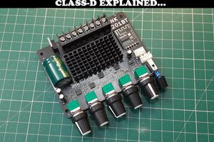
 Sagar 001
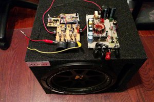
 Boolean90
 Szoftveres
Just love the brutally beautiful look of that tube!