 El Juanan
First of all, I've never documented a repair, and I think a lot of this project could have been executed better, but this is the way I did it. I'm just a hobbyist, I'm not an electronics engineer, so don't take my words as the truth. I put this into Hackaday ony for helping somebody with this scope.
0%
0%
Fixing the OS12 scope
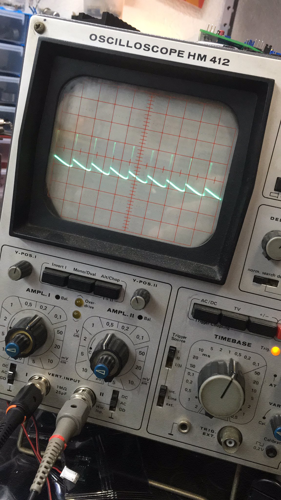
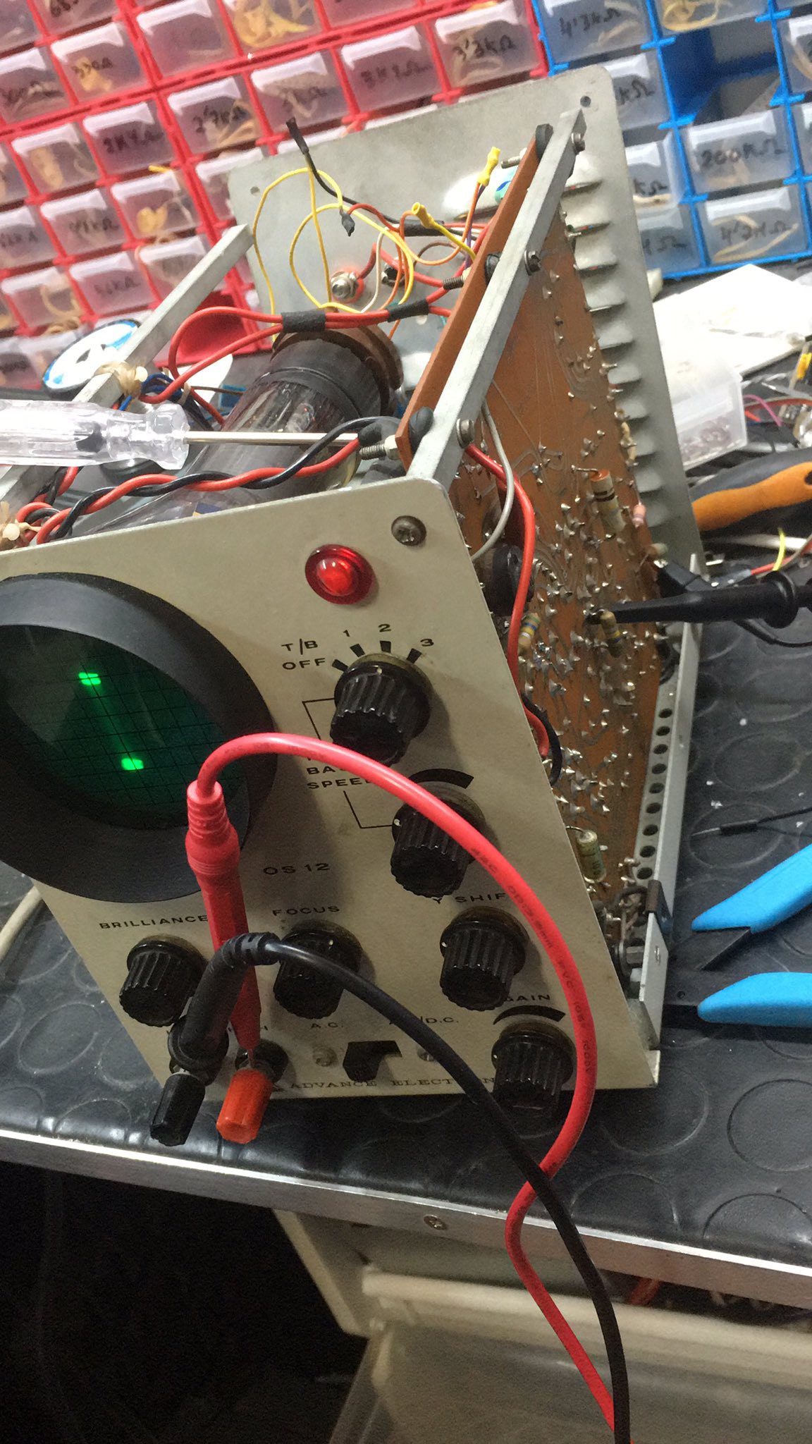
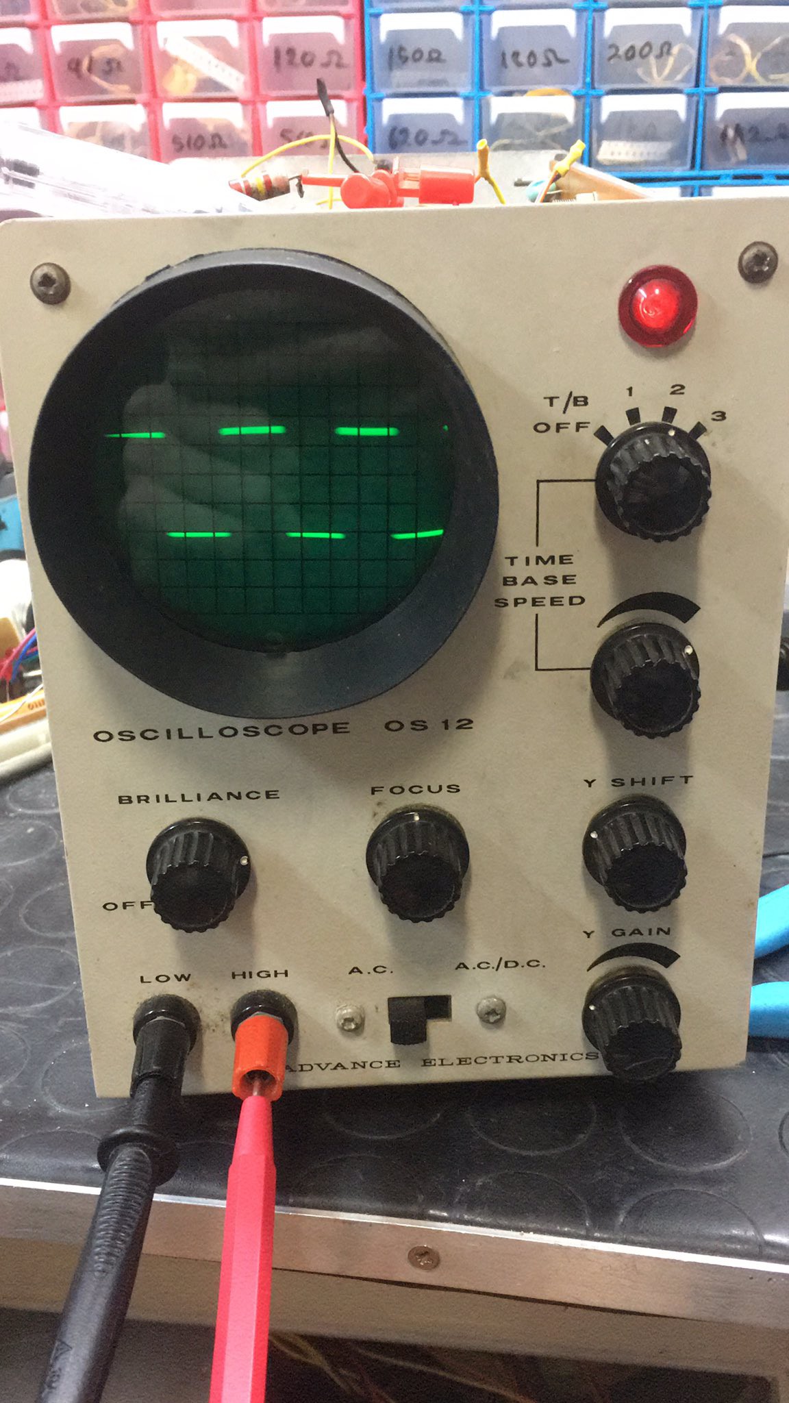
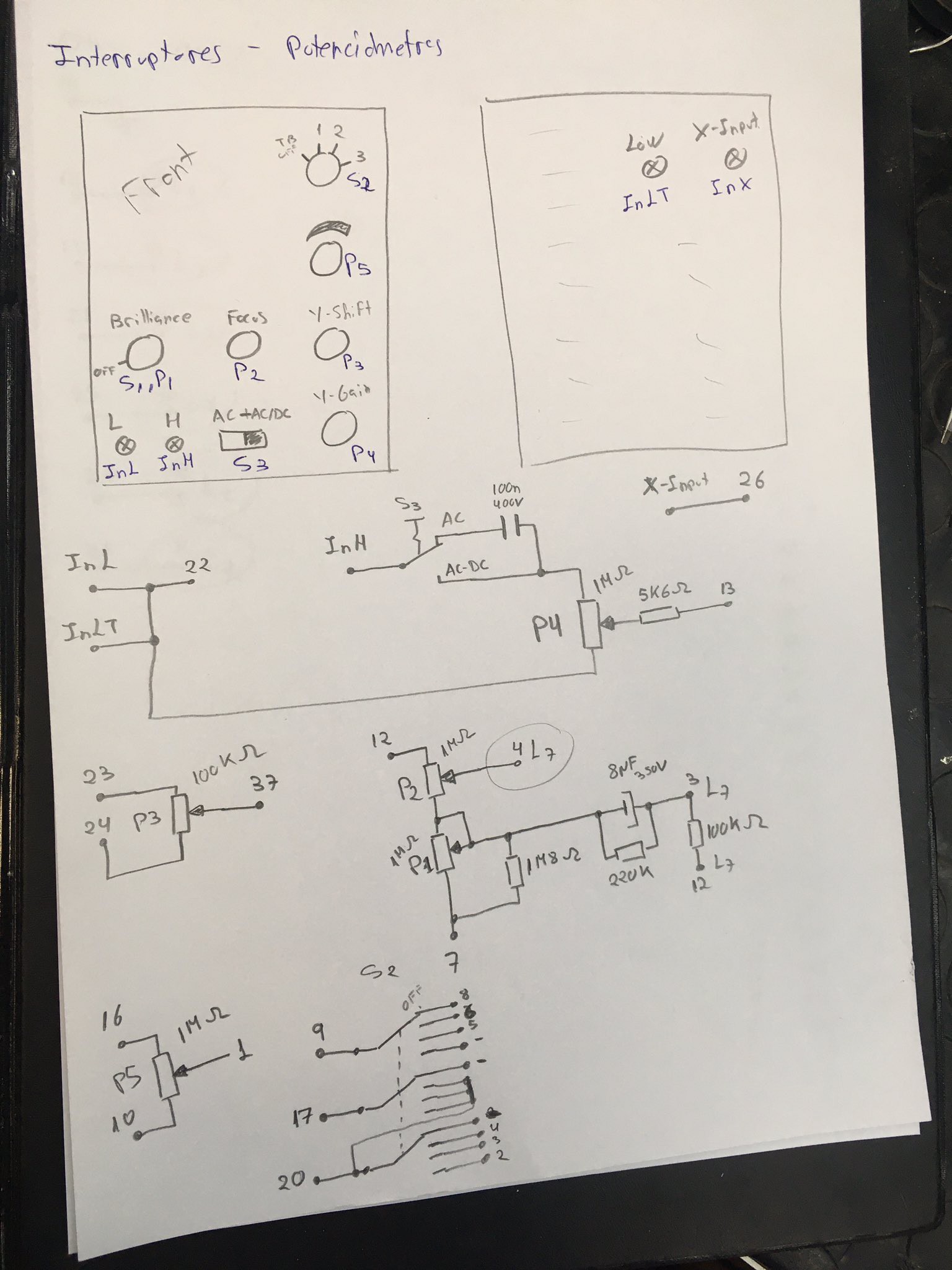
A quick tour where I fix an old tube-based oscilloscope, the OS12 from Advance Electronics.
Become a Hackaday.io member
Already have an account? Log in.
Just one more thing
To make the experience fit your profile, pick a username and tell us what interests you.
Pick an awesome username
hackaday.io/
Your profile's URL: hackaday.io/username. Max 25 alphanumeric characters.
Pick a few interests
Projects that share your interests
People that share your interests


 sky-guided
 SUF
SUF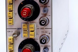
 Paul McClay
I'd date it from the early or mid 60s, there is a (I presume) later model from 1967, the OS25 (https://www.radiomuseum.org/r/advance_in_oscilloscope_os25os_2.html)