kelvinA
-
[T] Minimum radius issue!
08/03/2023 at 19:39 • 0 commentsThe current solution... may fail, due to: - turning radius requirements of the 3.2mm ball chain approaches the motorised sprocket diameter.So I've implemented some tweaks and learned a few things.
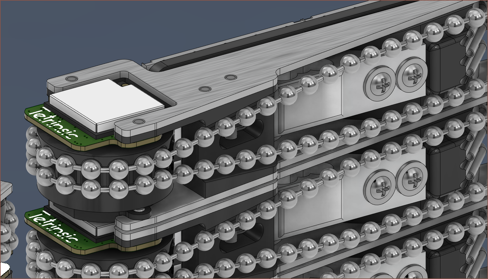
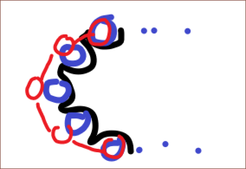
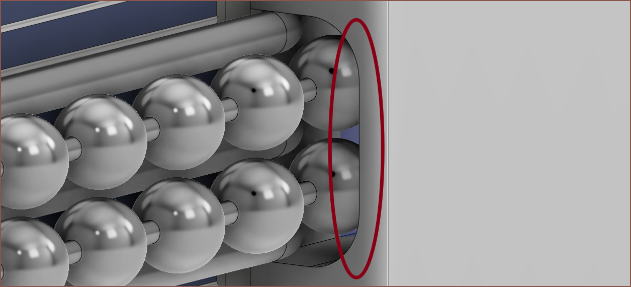
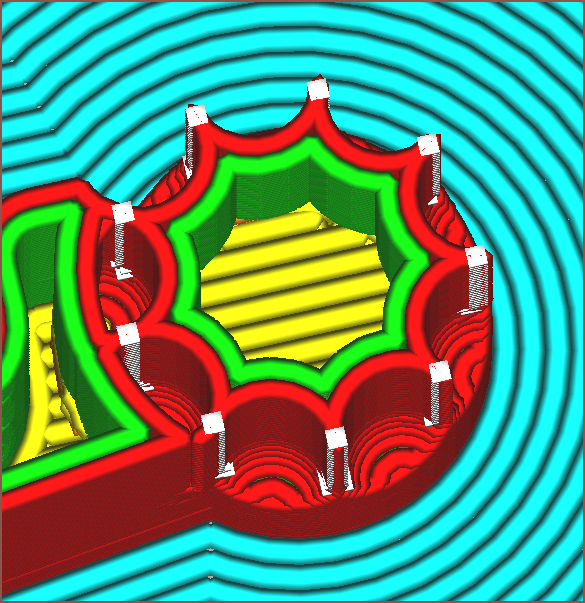
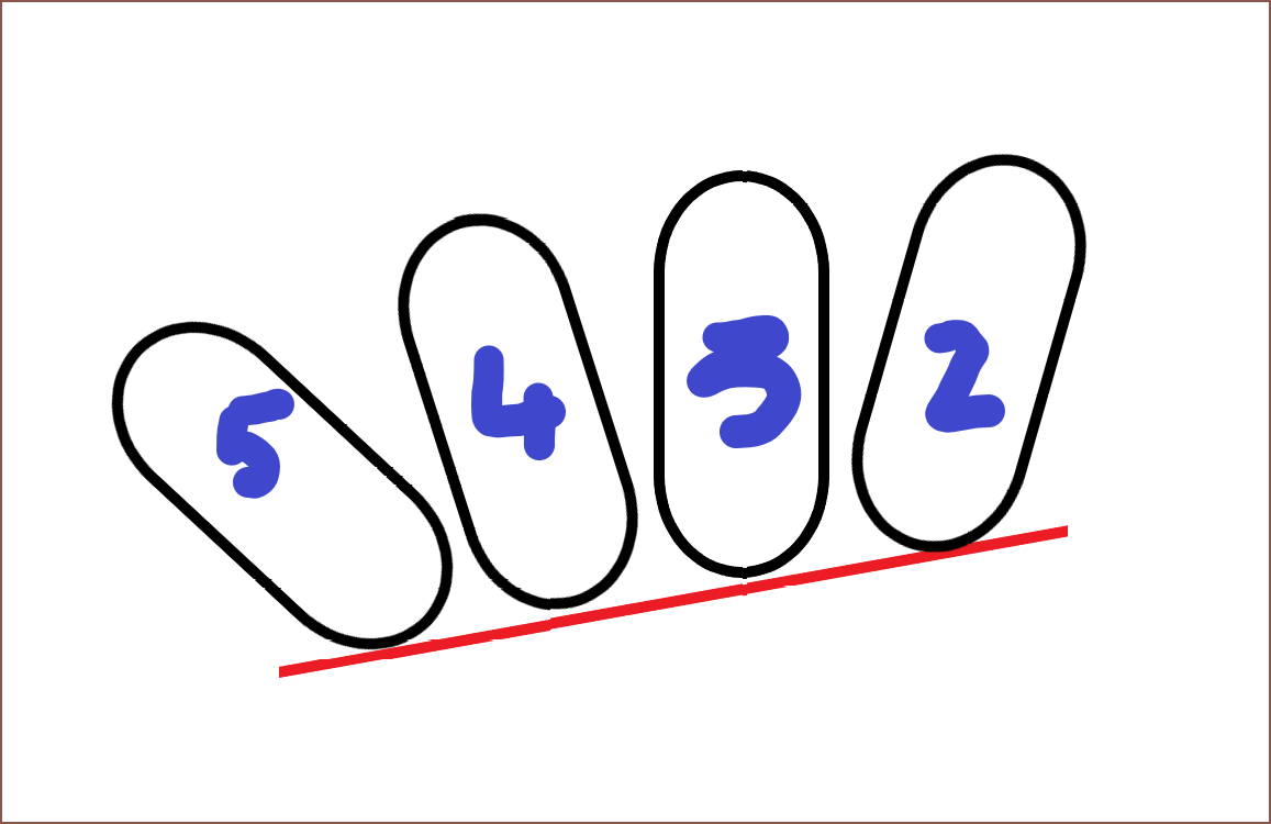
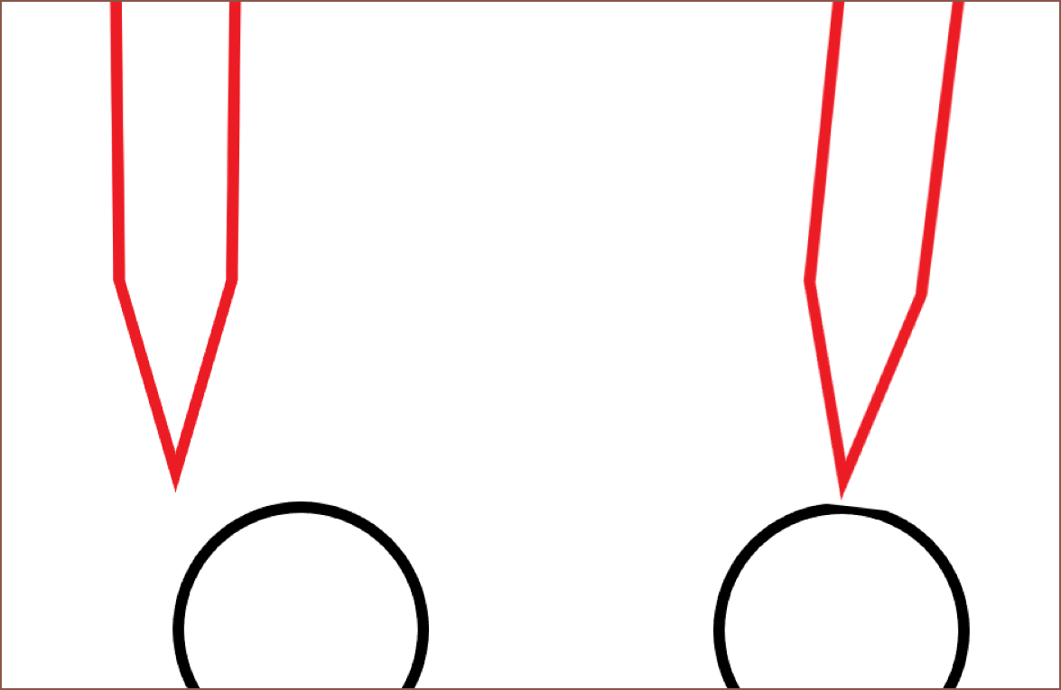
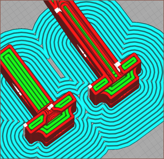
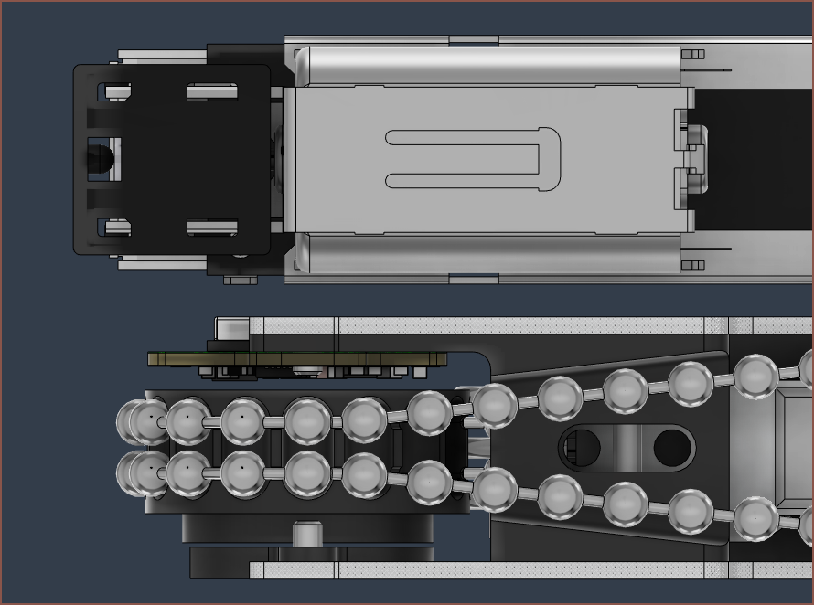
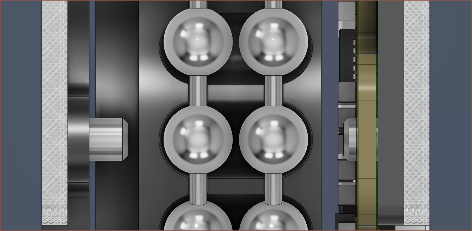
Firstly, unlike what I assumed months ago, the chain won't actually slot into the sprocket teeth if the teeth are too close together. Instead, the first and last balls slot in and the rest kind of hover in an arc:
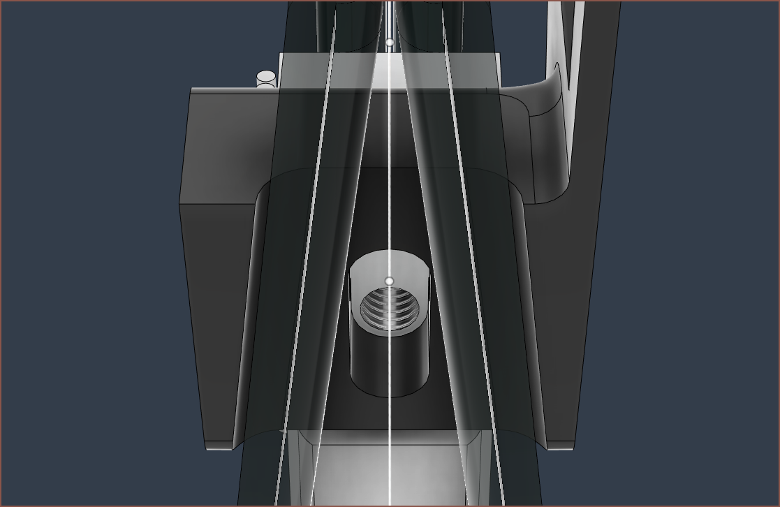
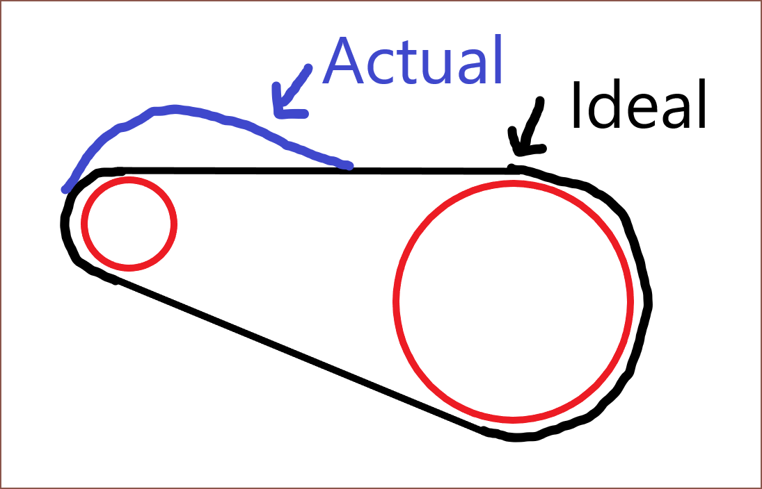
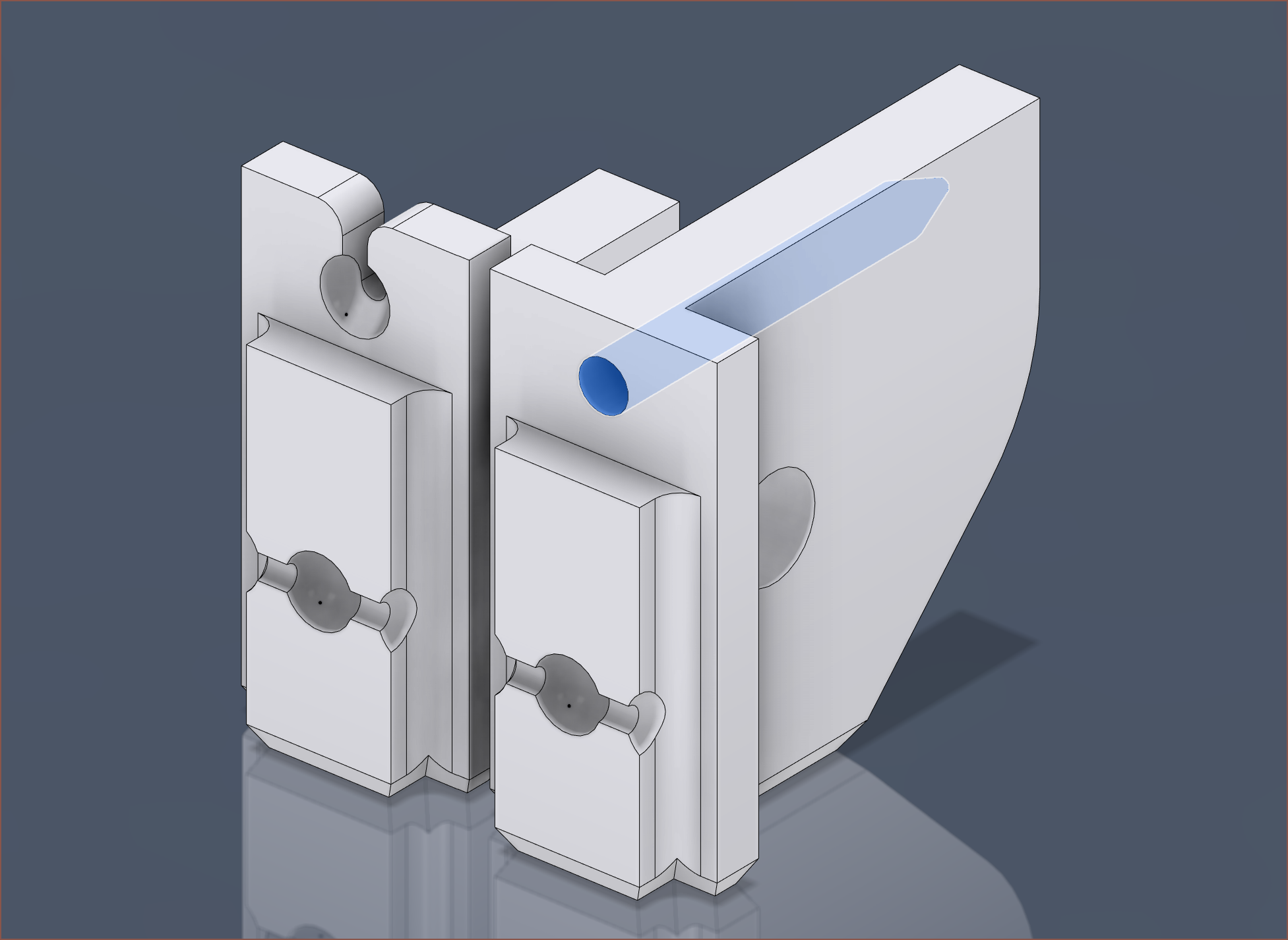
Purple is expected and red is actual. Secondly, its starting to seem that the 3.2mm chains natually tensioned turning radius is closer to the 16 teeth motorised sprocket than the 10 teeth unpowered front sprocket. It kind of makes sense now that I've actually got prints in my hand and the small bend does seem ambitious. This issue might be mitigated since there'd be a roof over the sprocket, but what is likely to happen is that the chain catches on the top edge of the entrance hole (see below), especially when in different orientations.
Taking costs and utility into account, it would overall be more beneficial to use dual motors. I know what I'd need to change in the file, but there's quite a few changes that would need to be made. I'll also have to assume that I need to be able to spin up the motors so that I can get both sets of poles aligned before I lock their rotations together via the chain.
The bigger issue is that the solution would cause the current Tetent concept to fail, mainly due to Finger5 as per usual. Sorry Me In The Past, but it is not safe to upgrade now.
-
[E1][M] Front Sprocket
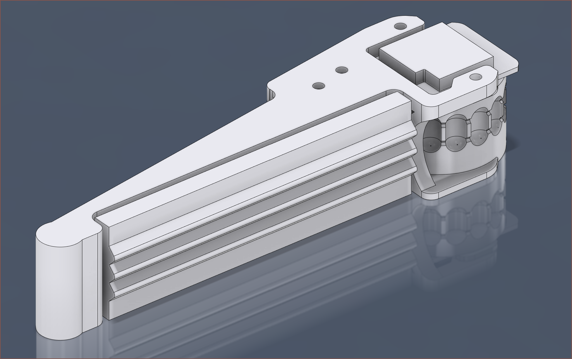
08/03/2023 at 12:24 • 0 commentsAfter considering my options, I've decided to continue trying to obtain a solution with 3.2mm ball chain. I've now modelled the front sprocket solution. I've spaced the front and back sprockets to be an integer spacing appart (I think 20 balls) and I've designed the front sprocket in such a way to ensure that the chain stays in the tube track throughout the length.
I'm somewhat hoping that I can use the pressure plate to tension the chain due to the deviation from a straight line from sprocket to sprocket.
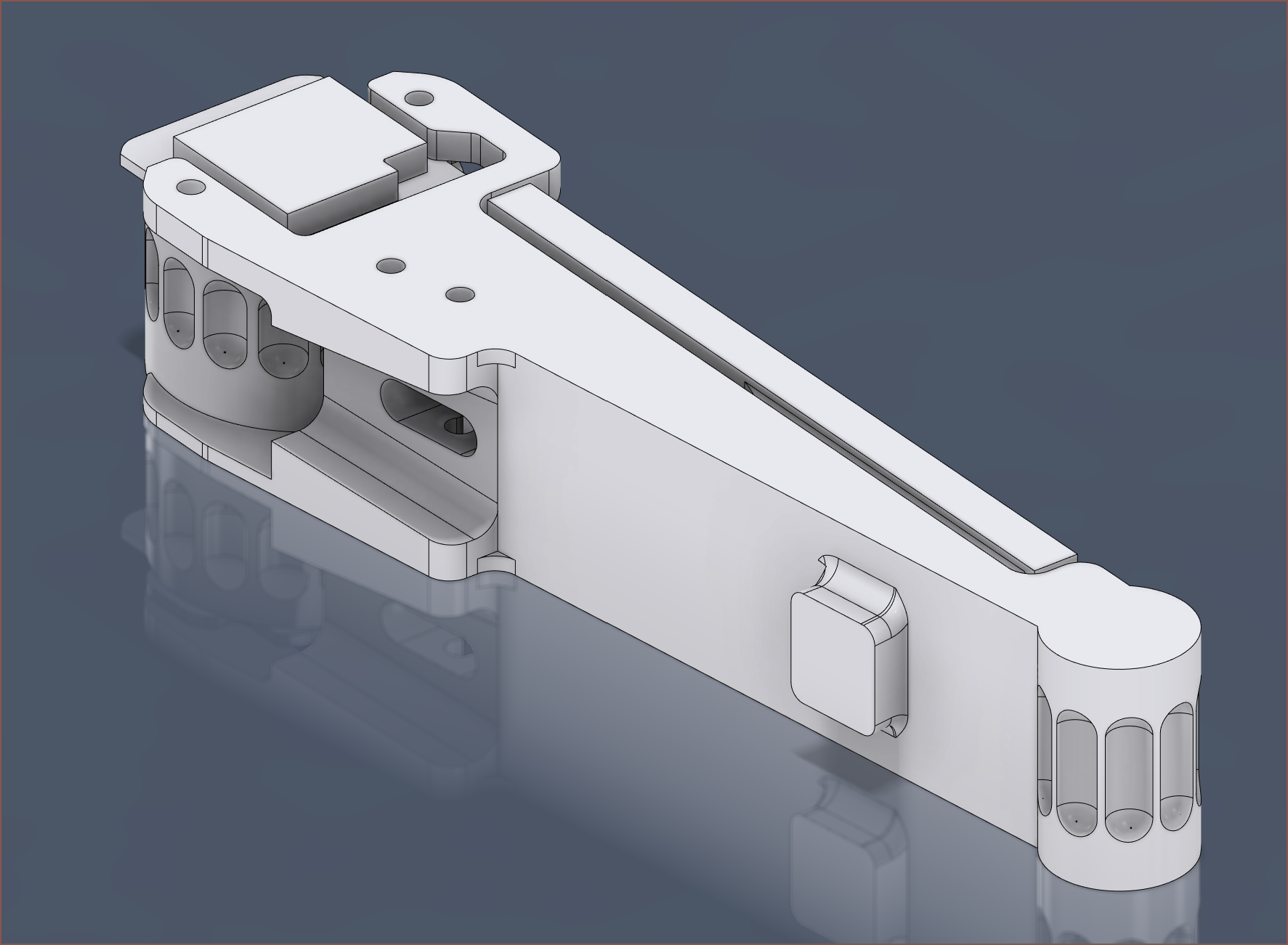
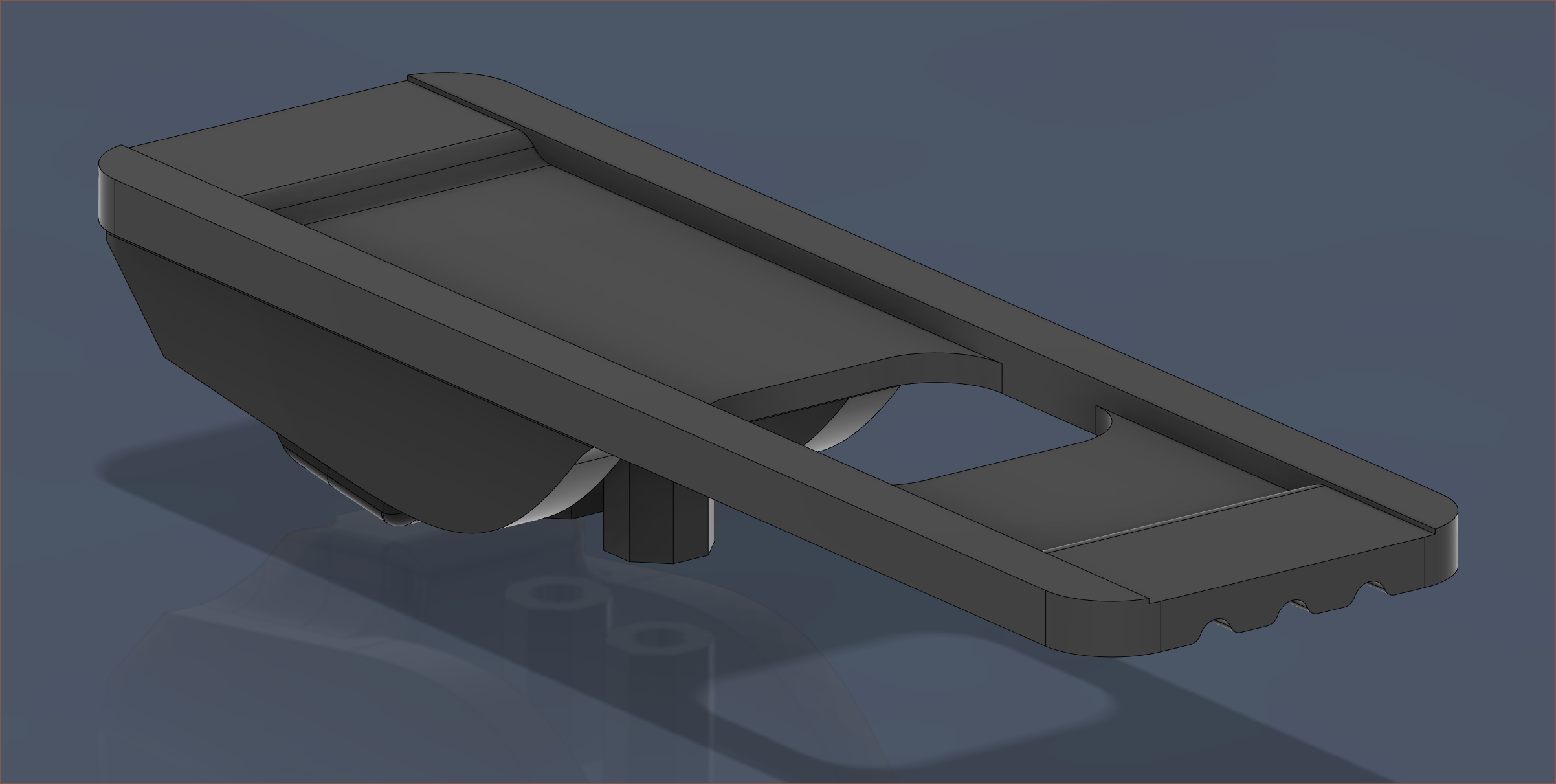
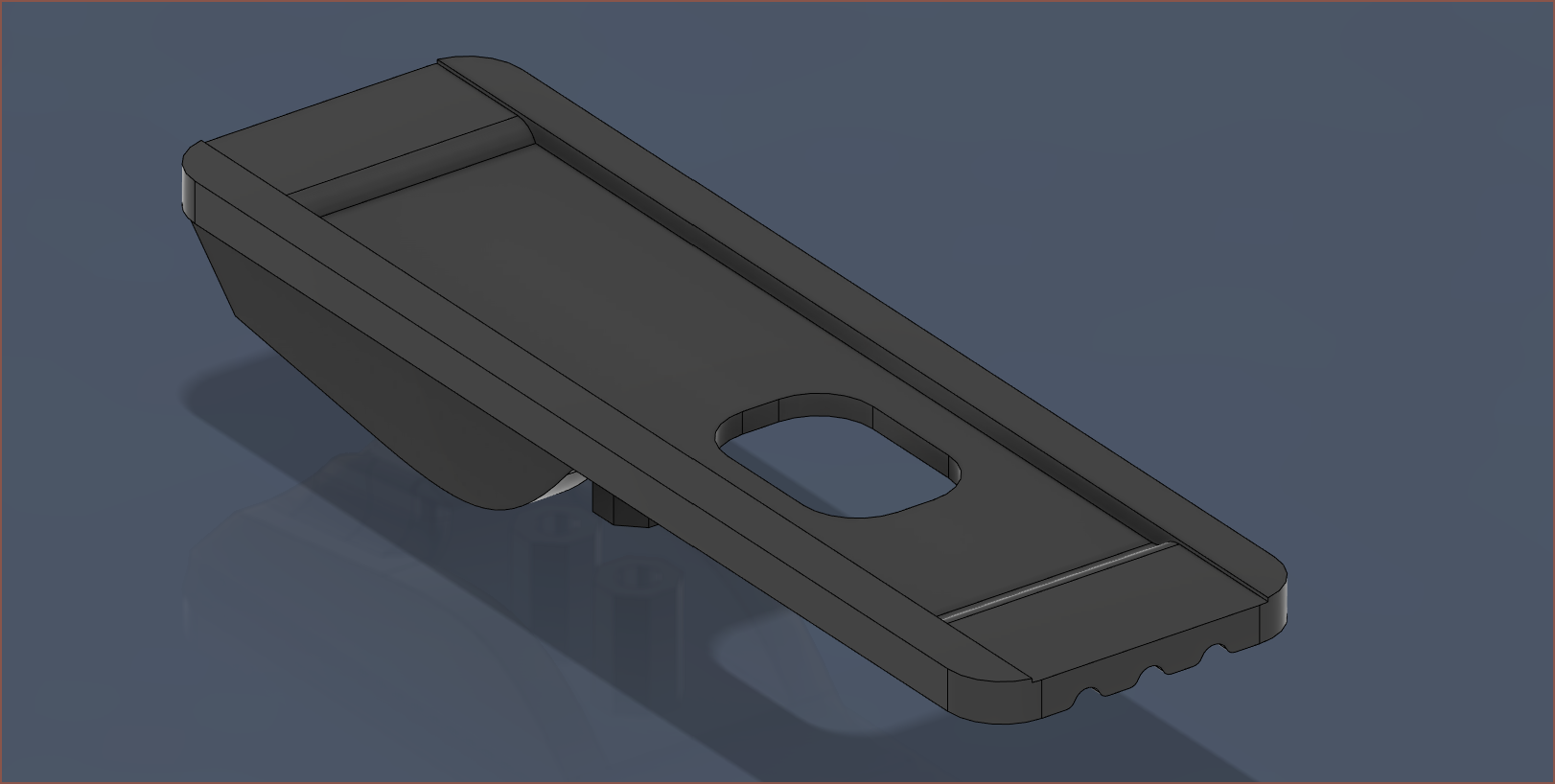
This is what the printable mockup looks like:
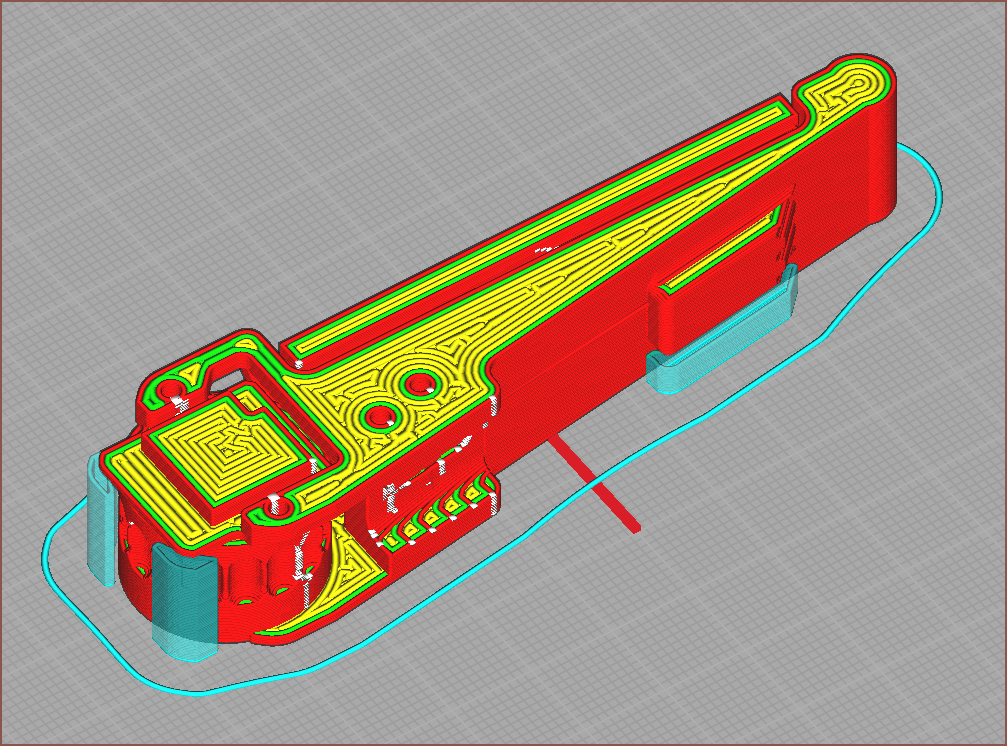
[15:15] I printed the above and I knew something was suspicious when the Cura preview looked like this:
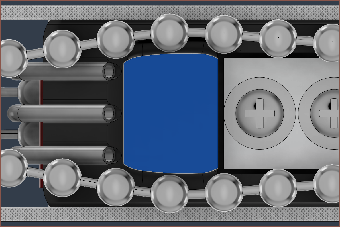
Those white squares are retractions. Essentially, those spikes have become all blobby when printed, so I knew I had to fix that and reprint. I also have to keep in mind that even professional SLS 3D printing a minimum wall thickness so I need to prevent the ends getting too thin. I've now added a special fillet to both sprockets:
Another thing I noticed is that the chain weakly caught onto the corners, so I've made the extrusion more cylindrical:
-
[M][P][T] Printable Concept
08/02/2023 at 13:04 • 0 comments[14:05] Now that I've got some way of splicing some loops, I can start printing out a concept so that I can obtain the correct tension required. One of the drawbacks of this design is that there isn't any way of adjusting chain tension and ball-chains themselves would be rather inflexible. I can only assume a 3rd pulley, connected via a flexure of some kind, would allow for looser tolerances in this regard.
The first print attempt is currently being printed as I type.
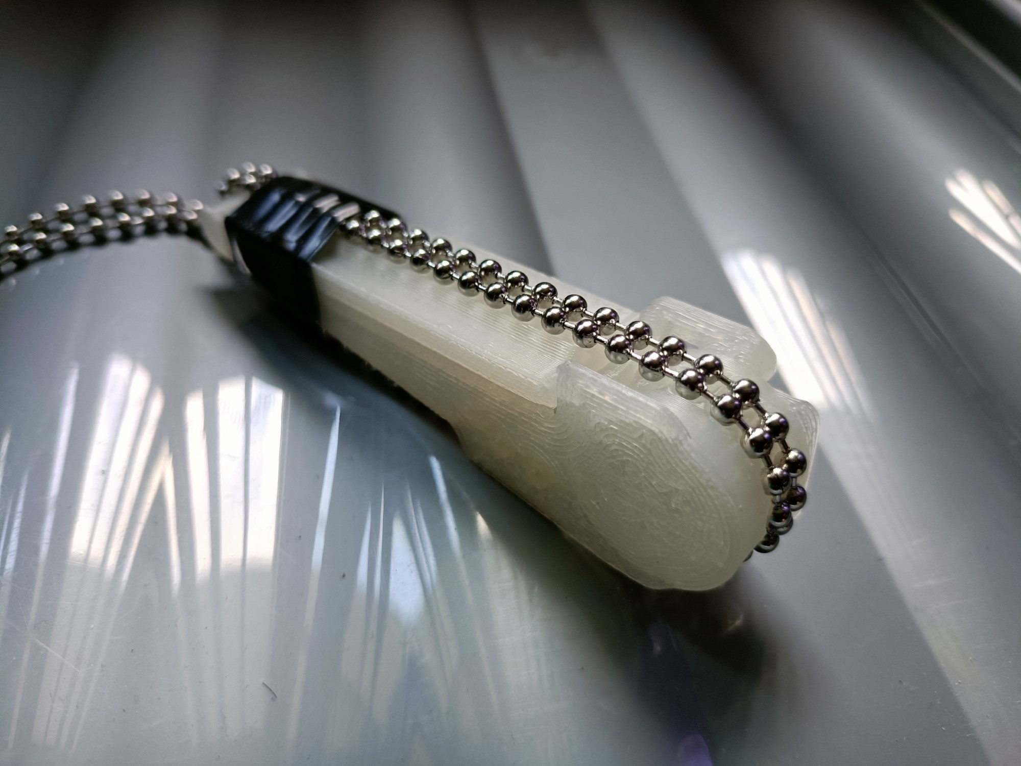
[18:00] So I used tape to hold the ball chain onto the print without even needing to splice anything. Looking back, I probably should've tried this weeks ago.
The good news is that it looks like the renders and it seems to work well with my fingernails; I actually have grip instead of the ice skating my fingers have to contest with on keyboards. Finger5, which seems to approach at an angle almost 45 degrees from the normal, seems to have rather good grip.
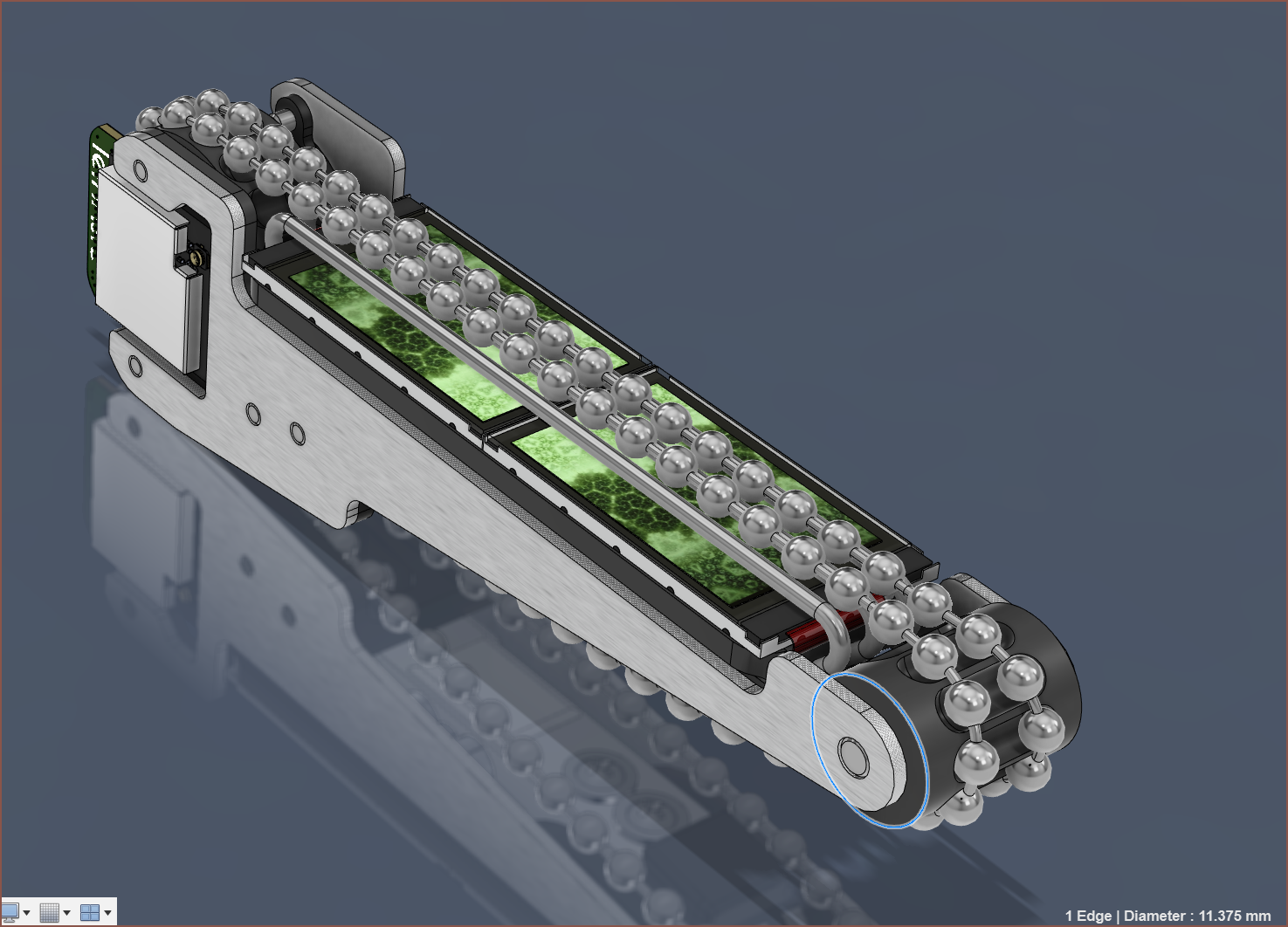
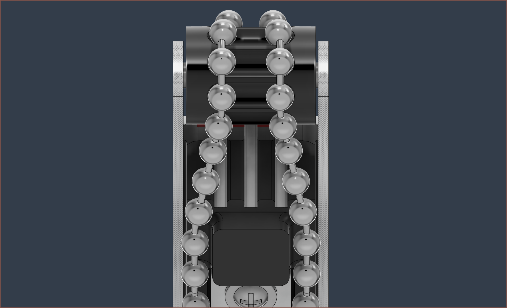
This is what it looks like when I grab my latest Tetent concept with my right hand, such that my palm is facing me. If slippage does occur, I think it feels more comfortable than a GT2 belt. The chain does sit inside the sprocket, but I think I'm near the limit before I need to add another tooth. Additionally, it seems that the chain doesn't leave the track when this Tetrinsic mockup is in varying orientations, such as upside-down. When my eyes are closed, it's easy enough to feel where the center of the chains are.
The bad news is that it seems that the chain won't make the 8mm diameter pulley bend without significantly lifting from the track (see below), as well as the understandable fact that the difference between tensioned and loose seems to be on the order of fractions of a milimeter.
I can't tell if I've engineered myself into a corner or if someone else designing a motorised, pressure sensitive linear slider would come to the same general design (e.g. a computer mouse having at least a left / right click button and a scroll wheel). The main requirement really is that Tetent works for me, not the other way around, thus that's the reason why a tangible requirement for Tetrinsic was natural fingernail compatibility; I didn't want to meticulously trim them (and lose out on their benefits in day-to-day life) just so I can type.
It doesn't help that the current best option for splicing is a £90 tool, but if Tetrinsic ever got popular enough, there'd be some AliExpress seller selling prespliced chains and so the tool cost would be a non-issue. I'm not sure if the issues discovered are showstoppers or not, but until I have something manufacturable, having to restart from square 1 is still a possibility.
-
[P] Maun 5066-160 Ball Chain Plier
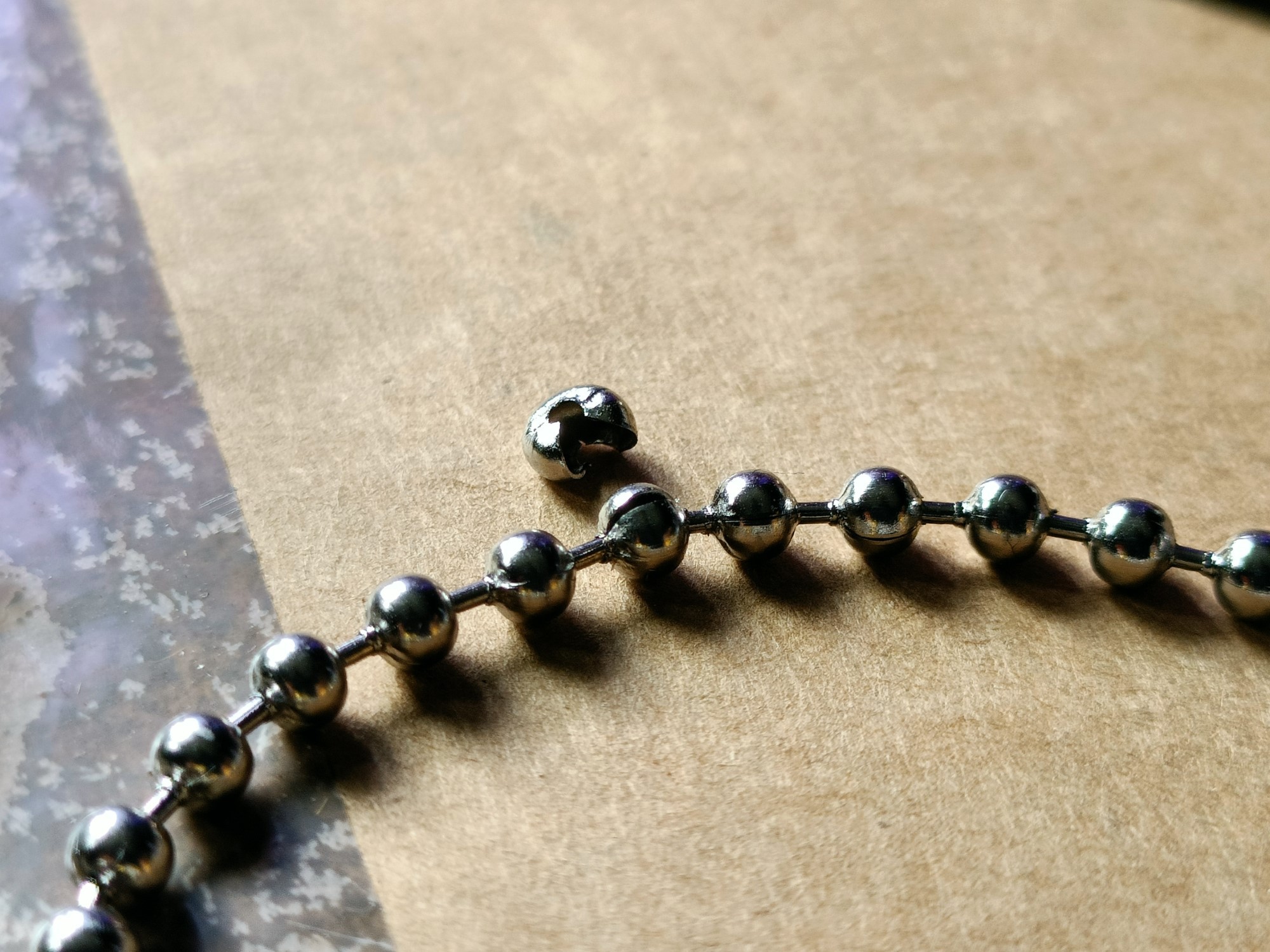
08/02/2023 at 12:30 • 0 commentsWell that was unimaginably easy. It didn't completely seal the ball but this was much more straightforward than my attempt.
If you couldn't tell by the title of this project log, that £75 (used) ball chain splicer arrived. The scissor movement seems to greatly reduce the amount of effort required to pin-crush the ball off the chain. I had a feeling that I'd have to create a fully 3D printed tool, since the ratcheting feature of the SN-28B was going to be an issue.
I feel like an improvement of the design would be a retractable stopper, preventing the spike from fully crushing the ball and just opening the insert hole enough to feed the linkage into it.
-
[M][P][X] 3.2mm ball chain splicer jaws for SN-28B
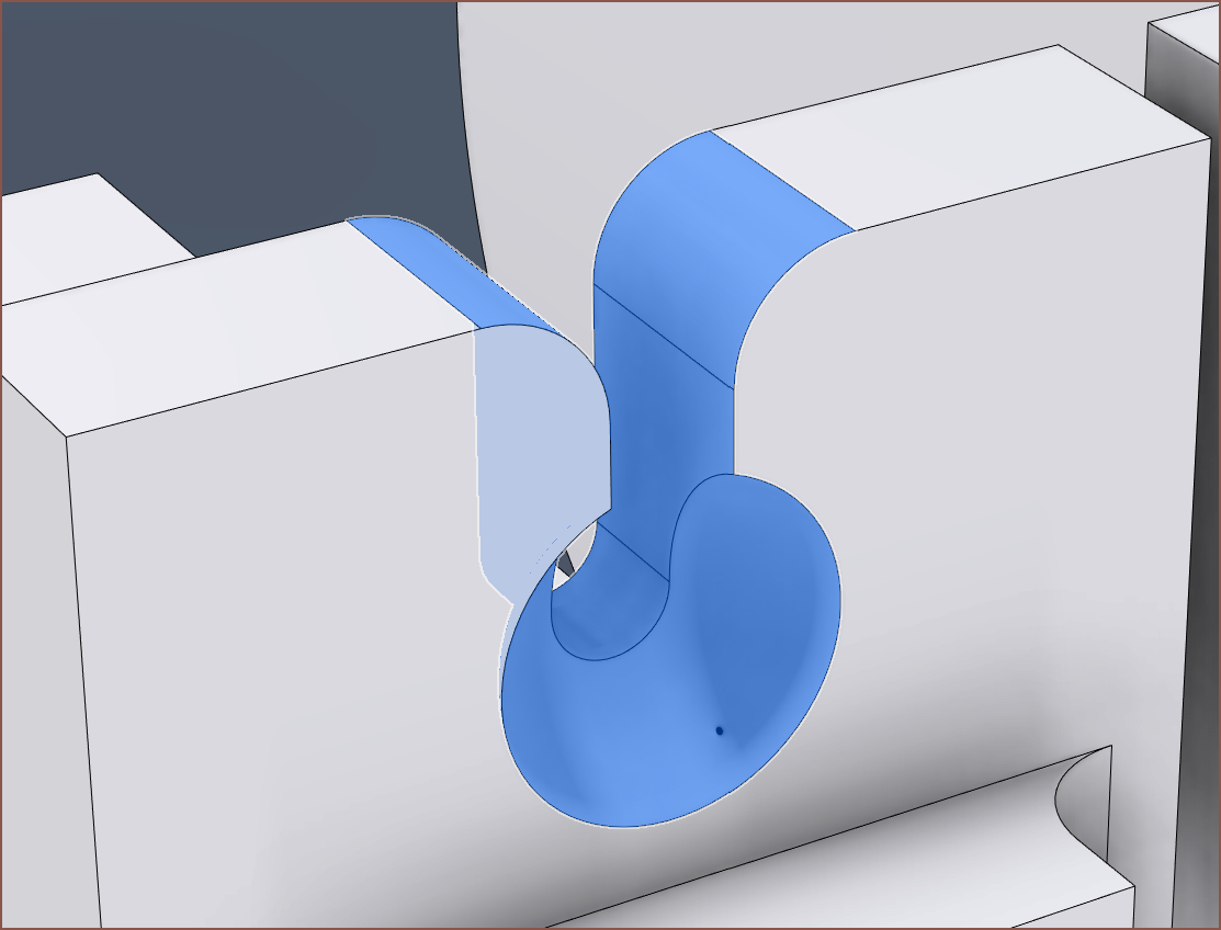
07/31/2023 at 17:19 • 0 commentsHighlighted is the void where the spike goes into. It's sharp on both ends. So I attempted to print out a set of jaws, following myinitial idea a dozen logs ago. Long story short, it doesn't work because the ball tilts when the spike goes into it.
Changes I had to make after my initial design:
- Change the spike hole from 2.2 to 2.4mm so that the spike could actually fit in the hole, even though the spike itself is only 1.99mm.
- Increase the side bolt hole size from 4.5 to 4.8mm
- Swap which side of the slot had the ball cutout.
- I originally had it on the other side, but that allowed the ball that was being stabbed to slide even more than in the configuration seen in the topmost image.
- Add cutouts of subsequent balls to the ball reformer mould
- Originally, it was just the one single spherical cavity. Now there's 2 more partial cavities on the left and right of it because the next ball in the chain isn't actually that far away from the one being reformed.
- Add a 0.6mm by 60 degree chamfer (using the distance and angle option in Fusion 360) because elephants foot was preventing the jaws from even going into the SN-28B.
- Change the width of the large rear wall (the one that has the side bolt hole) from 4.0 to 3.9mm.
- Moved the slot end so that it was slightly closer to the hinge end of the jaws than the spike.
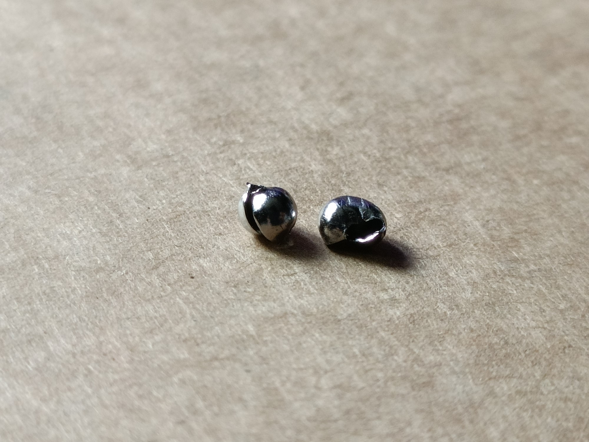
- This was an attempt to eliminate the asymmetrical ball opening that I'll talk about shortly. The left is how it's modelled in CAD, and the right is what happens in the real world, taking the slight rotation of the jaws into account as they close.
Basically, what I'm trying to say here is that I'm not a fan of the manufacturing stage because, like anyone in manufacturing would tell you, it's just as much of a grind as actually designing the thing in the first place. I don't have high hopes that I'd be getting #Tetent [gd0090] built anytime soon, and why I'm not even bothering with #SecSavr Suspense [gd0105] until after Tetent, since I'd most likely have to revise things a "Hey, there's Big Ben, Parliment" amount of times.
Anyway, this is the result:
The balls seemed to bend assymetrically; instead of evently splitting apart, the top hole would open loads and the bottom wouldn't open at all, and instead the sides would skew as seen above. Additionally, the jaw already broke after just 1 attempt:
It was printed solid (see below) so there's not much more I can do:
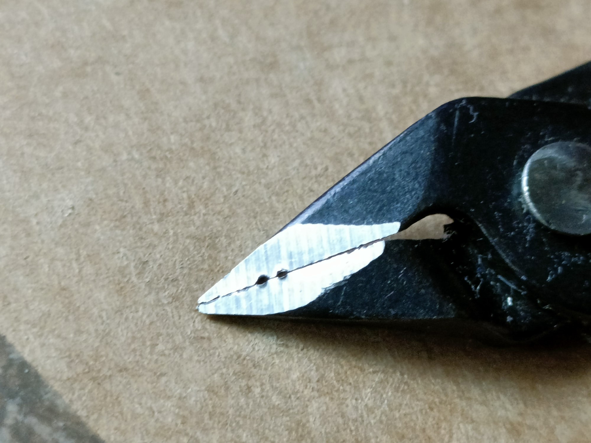
Oh, and actually cutting the chain left these voids in my nice cutters (that I mainly use for part cleanup). My long nose pliers fared much better for this task.
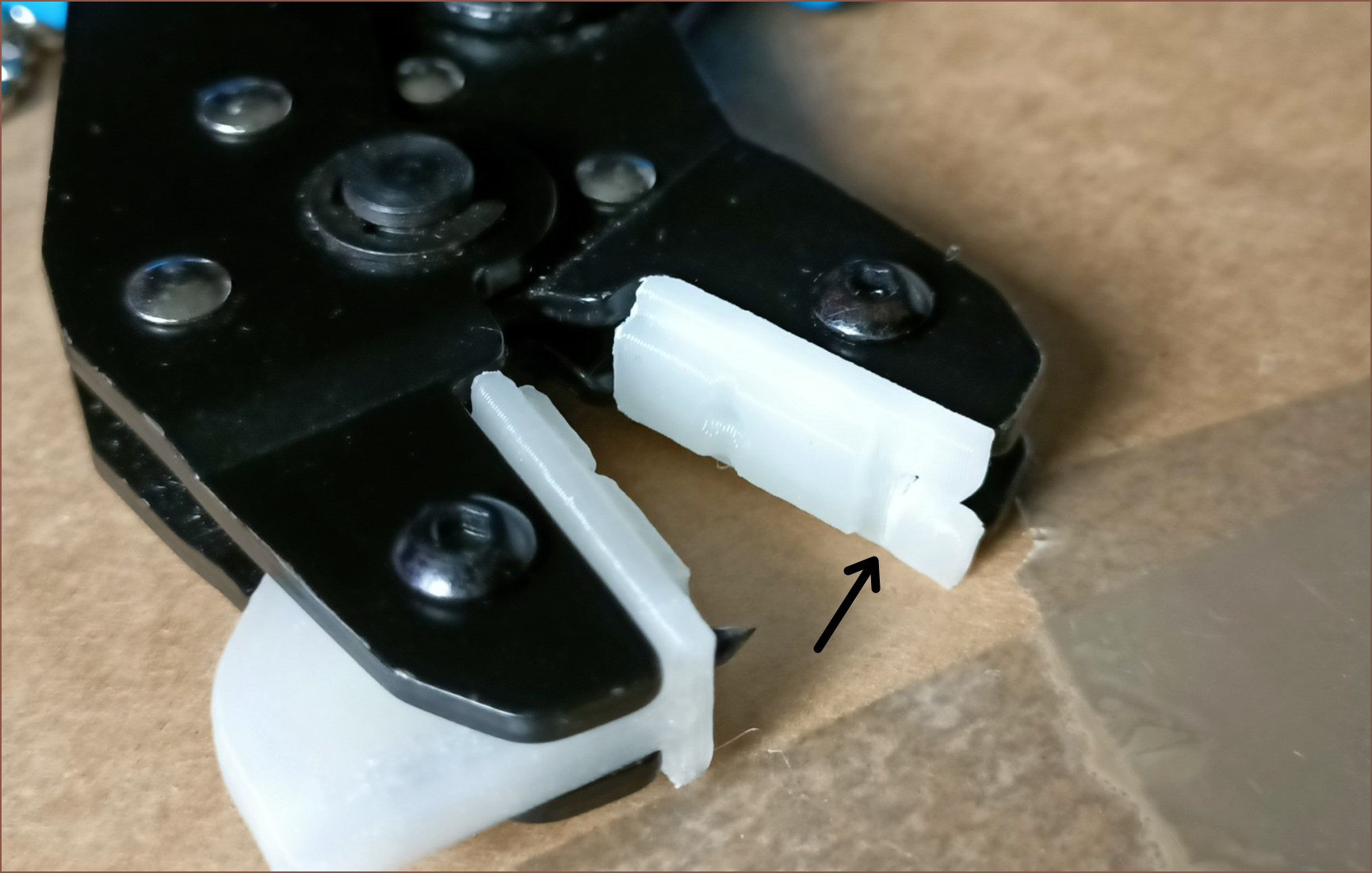
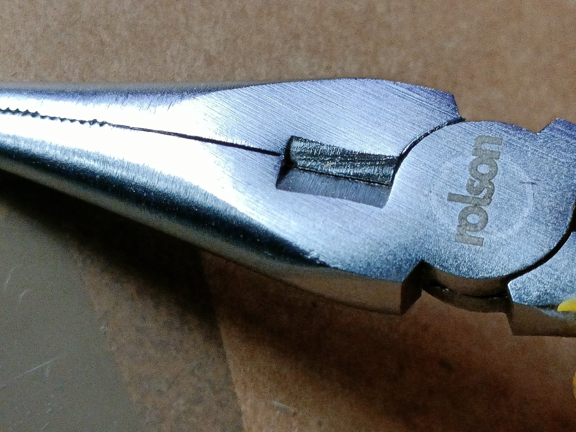
Speaking of these, I also tried using them in place of the 3D printed slot (see below), but I still got the asymmetrical seperation.
I'm tempted to buy a "Used, Like New" commercial tool to see if this is an issue with my design or if I've just got uncooperative balls.
-
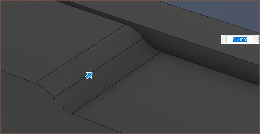
[M] Increased skeleton size
07/25/2023 at 07:34 • 0 commentsJust a quick update:
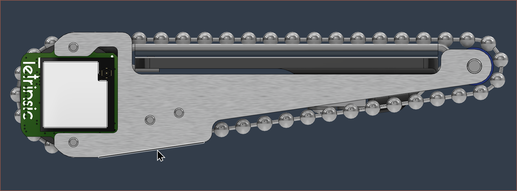
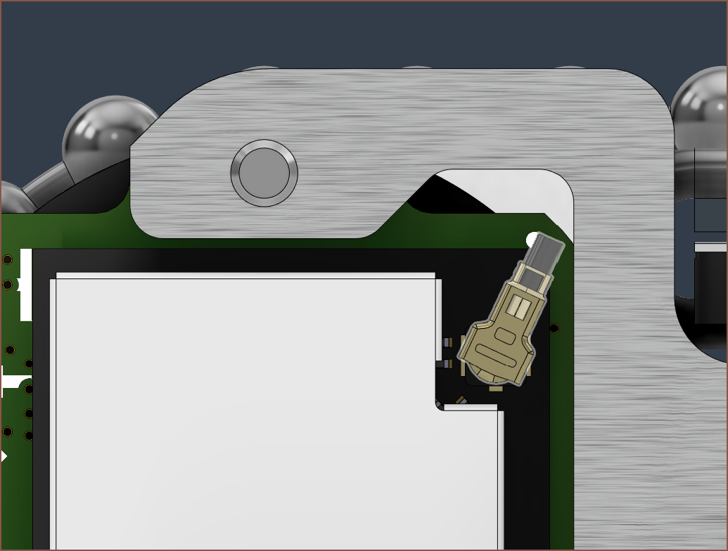
I had to make the skeleton side profile larger because the edge that my cursor is pointing to has to extend past the moving ball chain. I've also added a cutout so that the antenna connector can make its way out:
-
[R] RS60N11M9A0E Motorized Potentiometer
07/19/2023 at 01:39 • 0 commentsSo I was tweaking the Details page...
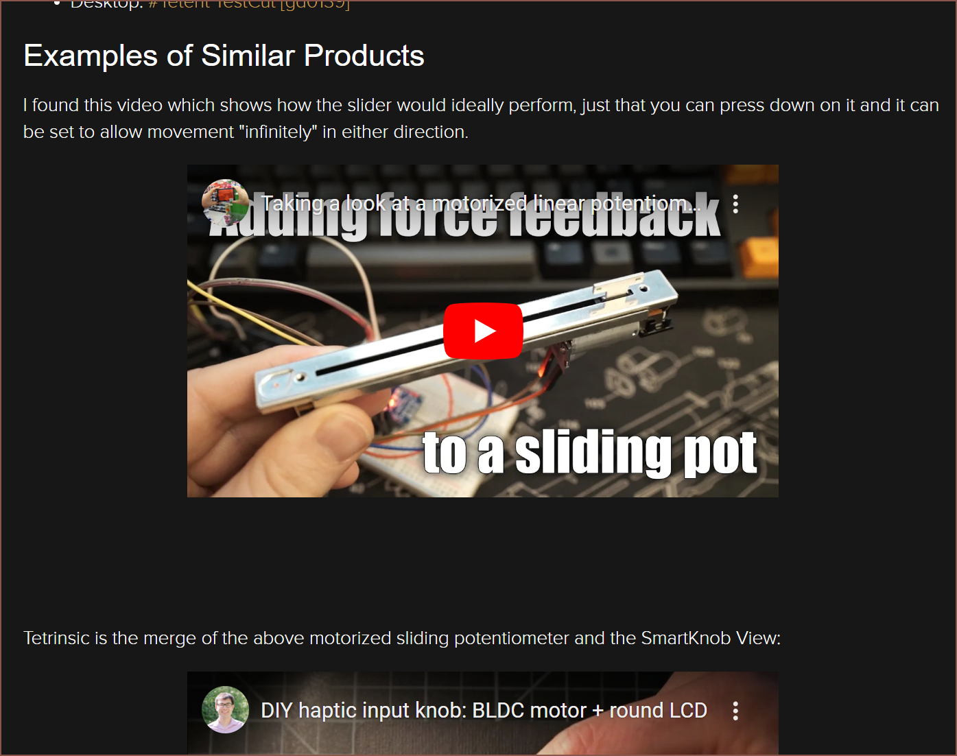
... and decided to look a bit further into motorized linear potentiometers, The last time, in 2022, I merely just did a quick search and saw that the pot was long and priced at about £30.
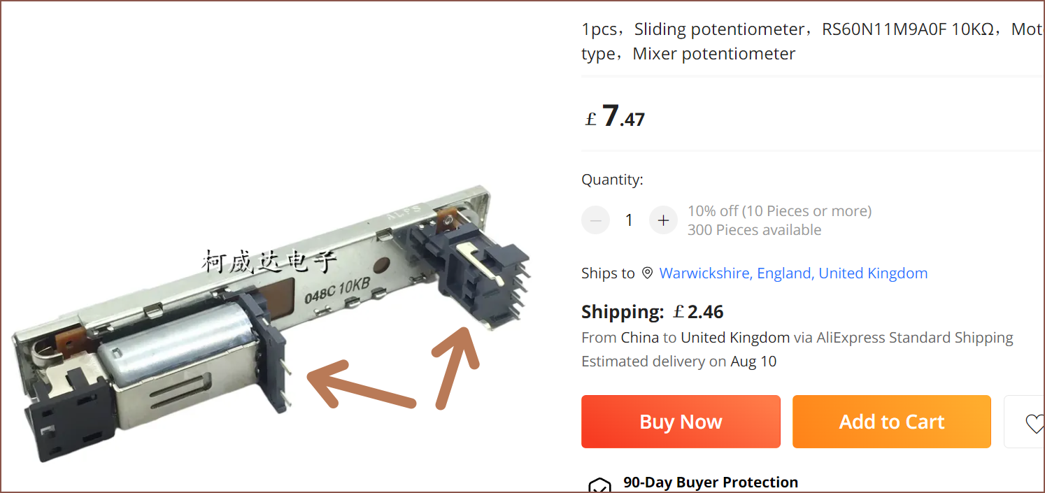
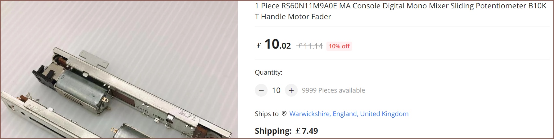
I did some searching on AliExpress and I found the RS60N11M9A0F and, subsequently, the RS60N11M9A0E.
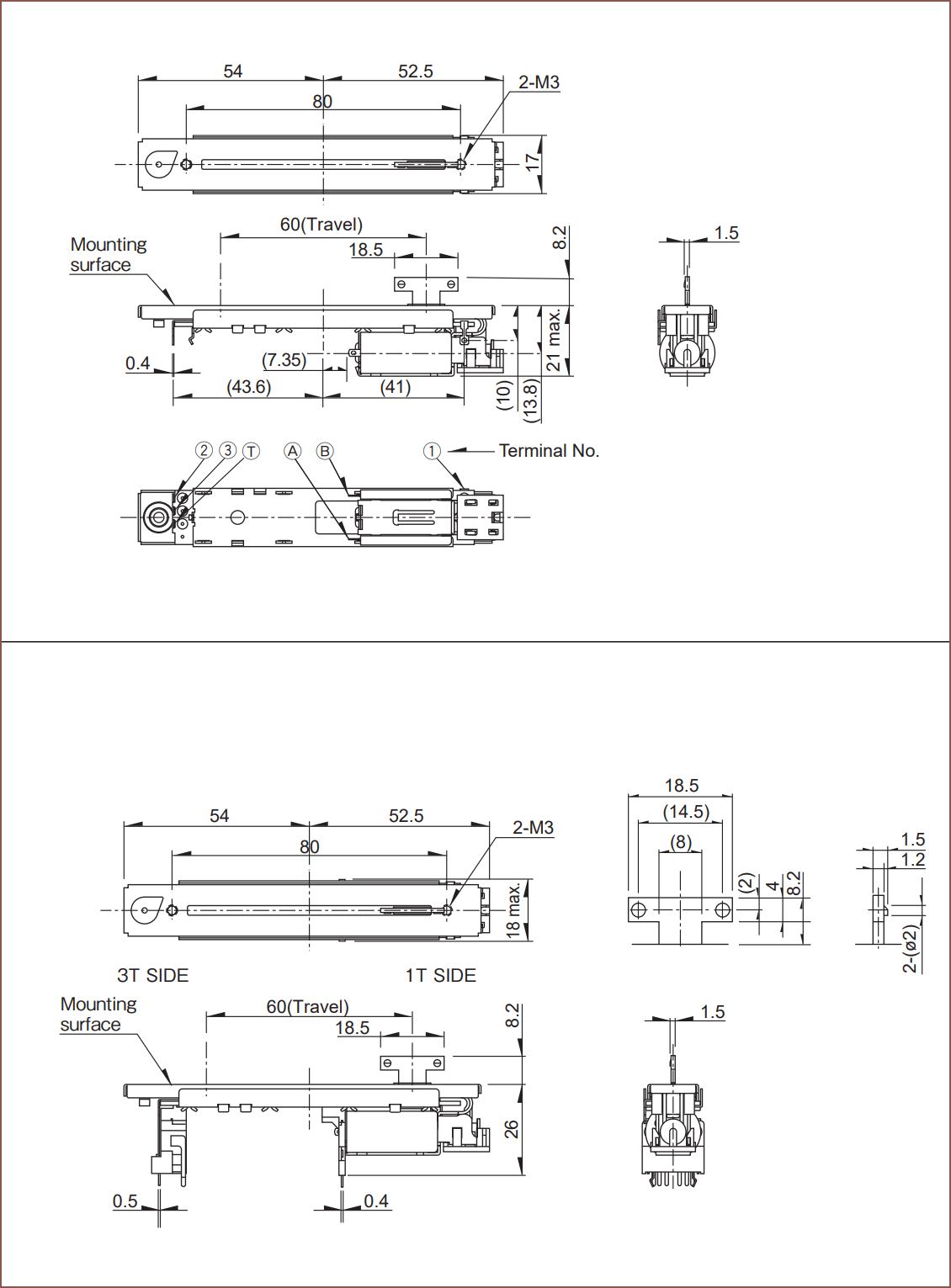
These two linear sliders are 106.5mm long and, at most, 18mm wide. The 0F is slightly larger due to these black mounts:
One AliExpress review on a different listing used it for the Yamaha ProMix 01, a device from 1995:
The 0E is a tad more expensive, but still only like £110 for 10pcs:
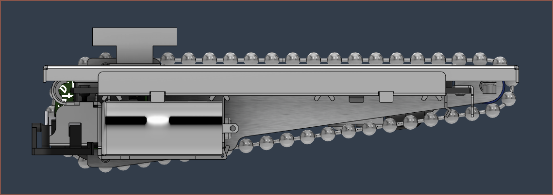
ALPS, the manufacturer, had a 3D model downloadable on their site so I've been able to import it into Fusion 360 to compare.
While the 0E only has a touch-sense pin instead of a pressure sensor, nor is bluetooth enabled or LCD backlit, the dimensions between this and Tetrinsic are very close. If anything, it's just that small black plastic piece at the back that sticks out and makes the 0E longer, though I wouldn't be suprised if I have to increase the length of Tetrinsic resulting from the ball-chain being too slack when made IRL.
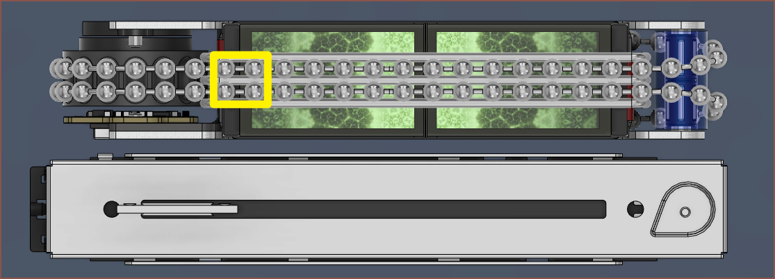
Each finger grip zone (yellow rectangle in image above) is about 8mm, so I could say that Tetrinsic has a stroke length of 55mm. The 0E has a 60mm stroke length.
It's nice to know that I won't be completely solutionless if the BLDC motor I've got now doesn't work out for whatever reason. I'd just have to go to a brushed DC motor. The motor that ALPS uses is rated at up to 10V 0.8A, and there shouldn't be much of a reason why the BLDC and circuitry in Tetrinsic wouldn't be able to do the same, since I've been planning to use 9V at a current limit of 0.6A.
It's actually sounding like, as an input for a digital system, Tetrinsic could be somewhat of a high-tech alternative, considering the similarities in dimensions and compatible motor voltages.
-
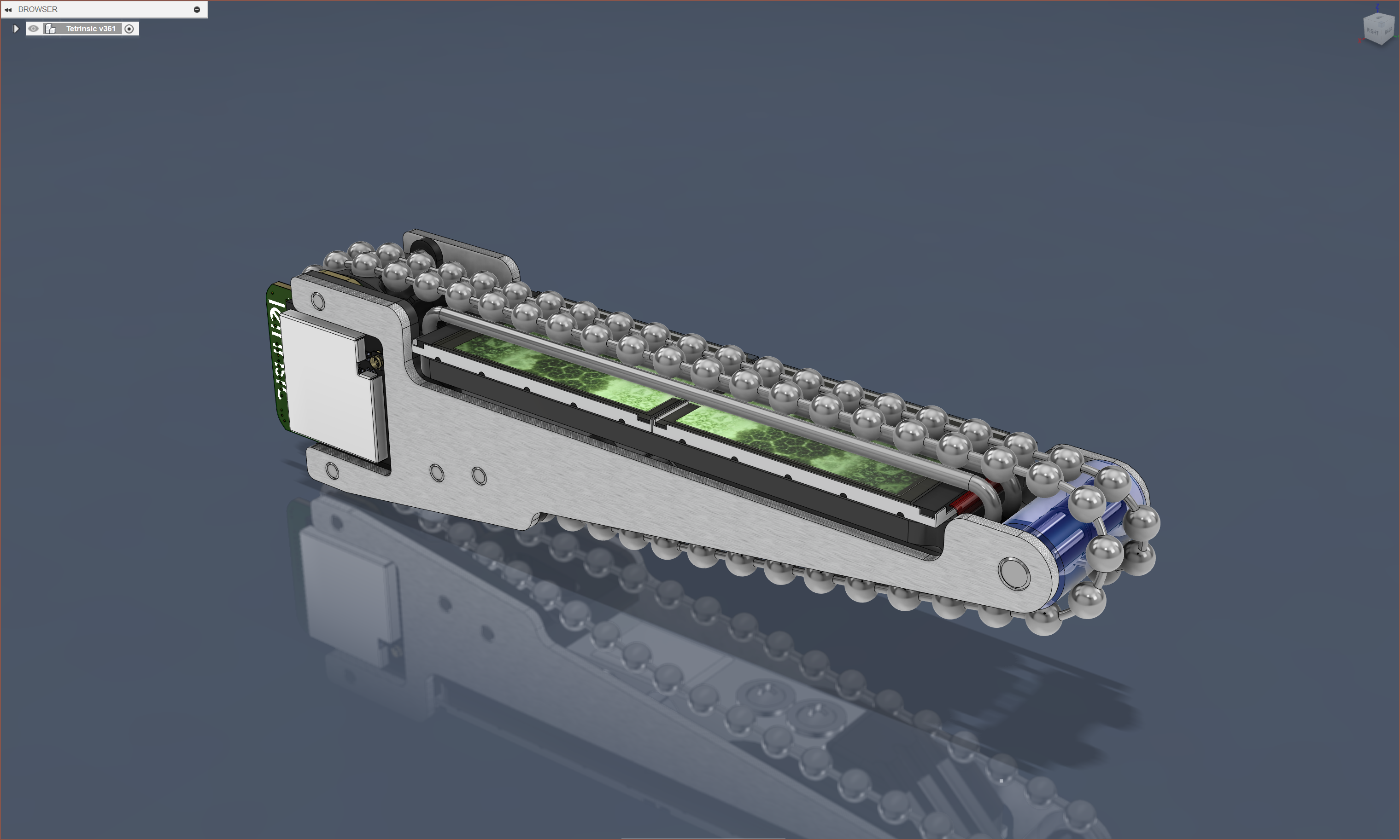
[M][L] Dual 1.14" PCB (and prototype's CAD and eCAD finished)
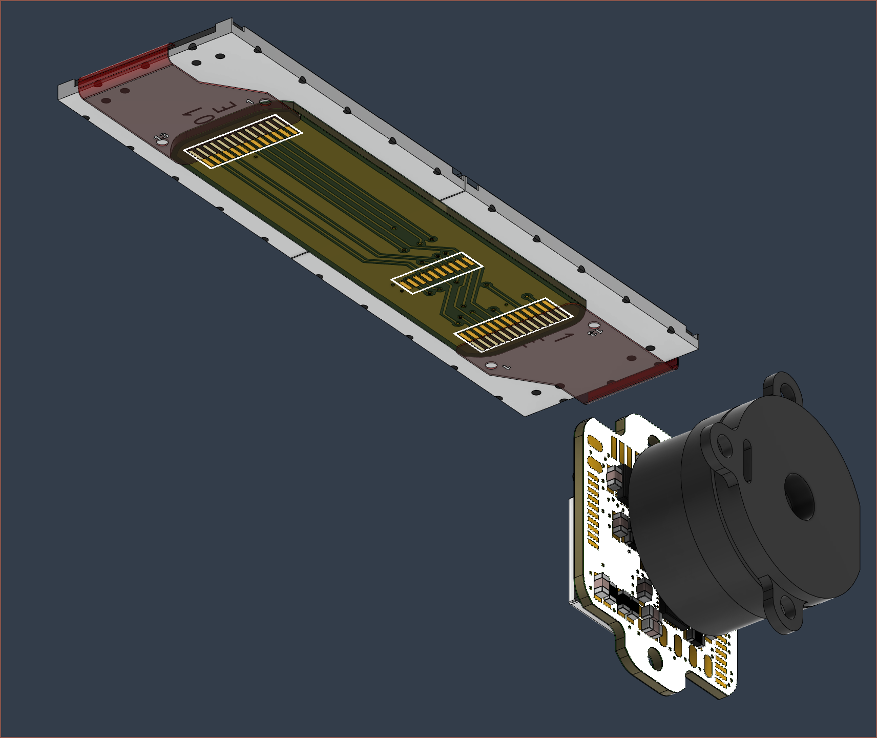
07/18/2023 at 05:59 • 0 commentsSo I've spent the past 6.5 hours working though Fusion 360 crashes to bring Tetrinsic v361 into existence. I've replaced the old 1.47" pad with a new custom pad for a PCB that connects the two screens, converted the FPC of the displays into sheet-metal components (so that I can adjust the bend radii and position) and adjusted the pressure plate, as seen below.
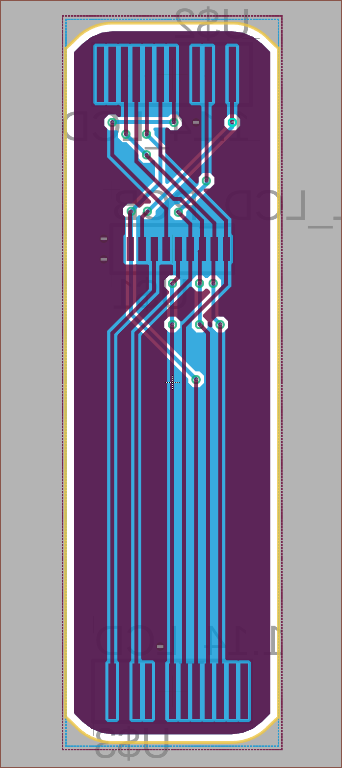
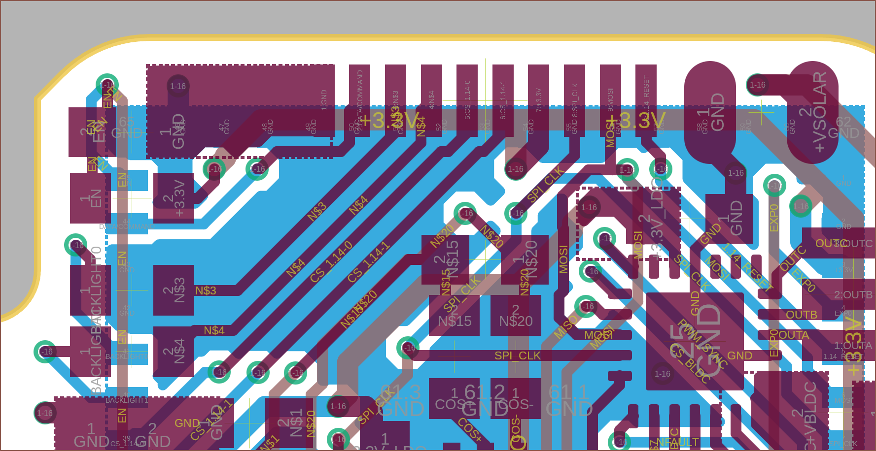
The routing of the PCB was a bit of a rushed job, but I think it still turned out elegantly. I havent' really done all that much in terms of silkscreen though.
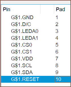
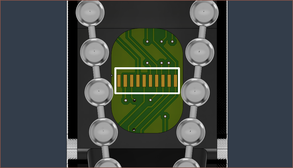
The pinout of the connector is shown here:
The pins were chosen such that it was possible to route the traces on the Tetrinsic PCB. Sadly, I had like 3 crashes just doing the last trace. This reminds me of what Fusion 360 3D design used to be like. It seems I'm only getting crashes when routing a trace.
I'm also thinking about using 4mm alignment pins for the BLDC too, to reduce the amount of unique components. I was planning to use that extra space on the sprocket for a grub screw, but I don't think I'd be able to fit it in anyway and a friction / glue attachment should suffice instead.
Now that I'm writing this log, I'm looking at the cutout for the 1.14" screens and it seemed like I should reduce the width to increase the strength of the pressure plate due to more material available on the sides:
It's actually starting to look somewhat professional now. [Spoken like an Apple executive who's summarising a new product as the summary slide animates in]: So there you have it. After 361 saves, this project concept has grown both in size and featureset and is now electrically and mechanically complete (unless I'm forgetting something). I won't know if it's manufacturable until I try, though.
Oh wait, there's something not quite right about the pressure plate fillet screensnip above...
Ah. Fixed. Ok, 362 saves.
-
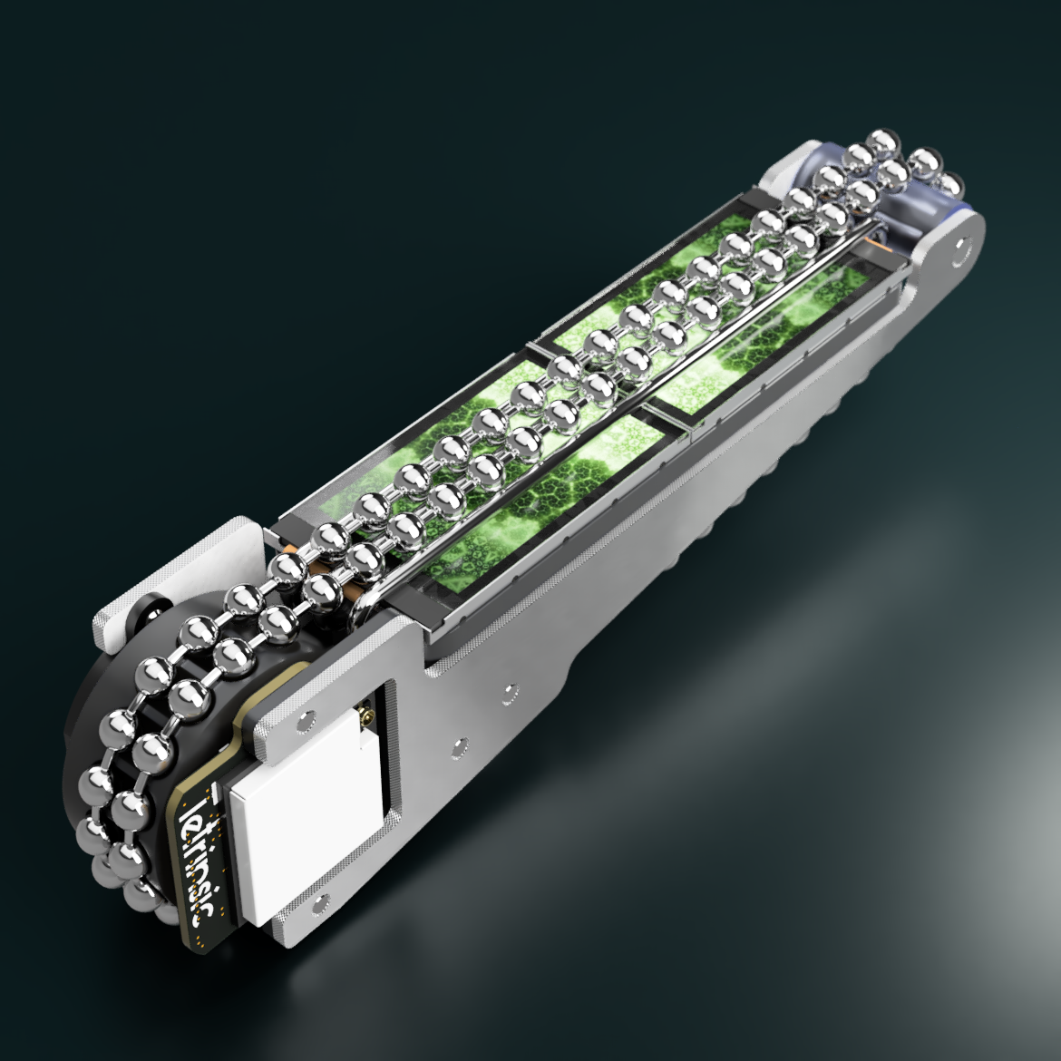
[A] New LCD background image and renders
07/17/2023 at 06:56 • 0 commentsSource of background: https://wallpaperscraft.com/wallpaper/fractal_shapes_glow_235436
Hue changed by 240 degreesI'm finally closing in to a similar completed state as the very first Tetrinsic concept, hardware-wise. I thought it would be a good idea to commemorate the relatively radical redesign of Tetrinsic from a dual path, single LCD solution to a dual LCD, single path one by finding a new background (see below).
Unfortunately for me, it seems that this entire process has taken 3 hours -- 2 for choosing / editing an image and 1 for setting up the render. Part of the 1hr setting up the render was to do with setting up slightly more accurate textures of the plates, such as the white soldermask or rough milled textures of the edges.
It's also interesting to know that I'm now at save v359. Only the #SecSavr Skyrise [gd0092] has more saves (v385) and that's an entire FDM printer. I guess it's to be expected, since digital input devices are used by billions and so all the low-hanging fruit of faster input methods have likely all been found already.
Tetrinsic Taic looks really cool and every past version of myself in the last 15 or so years (whenever the Horizon Fuel Cell H2Go RC Car came out) would be happy to know that a futuristic input device may very well be powered by renewable energy.
This log took 50 minutes to create. -
[M] Frame connector and pressure plate pusher
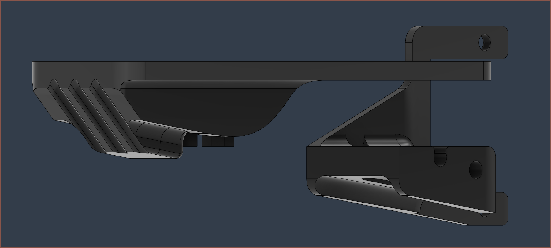
07/17/2023 at 03:24 • 0 commentsI've now modelled the 3d print that connect the two frame plates together, as well as modified the pressure plate to push the ball-chain around the load cell.
The plan is to use 2mm dowels as locating pins and then glue the frame plates together. The frame connector also acts as a spacer for the PCB. For mounting Tetrinsic to something, the frame acts like a massive spacer between the load cell and attachment surface. To put it another way, the M3 bolts go through the mounting surface, then the frame connector (narrowly missing the ball-chain path) and finally screw into the tapped holes of the load cell.
Hopefully, the tension of the ball-chain keeps the load cell + pressure plate assembly somewhat fixed in place during assembly.
Tetrinsic [gd0041]
A continuous, motorised fader that is pressure sensitive, haptic and water resistant.


 It's also interesting to know that I'm now at save v359. Only the
 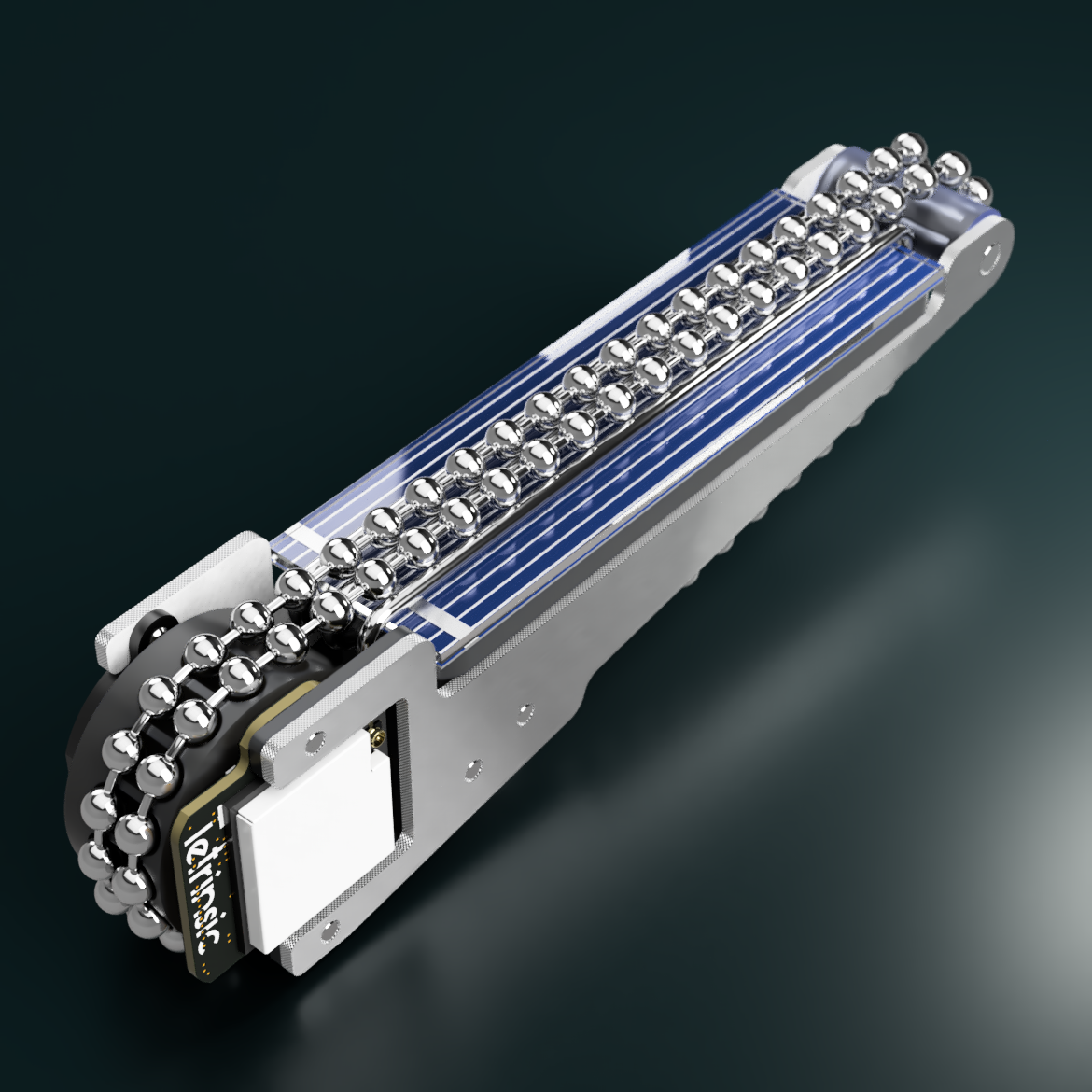 Tetrinsic Taic looks really cool and every past version of myself in the last 15 or so years (whenever the