kelvinA
-
[T] Idle thoughts
10/09/2022 at 17:50 • 3 commentsThis is a place to put any discoveries I find, if anyone was looking at this project for inspiration.
-
[A] Uploaded v72 .step file
07/31/2022 at 02:09 • 0 commentsThe CAD is still very much incomplete, but I also dislike when someone says they intend to upload the CAD data, but only after they've "cleaned it up".
-
[P] BTT CB1
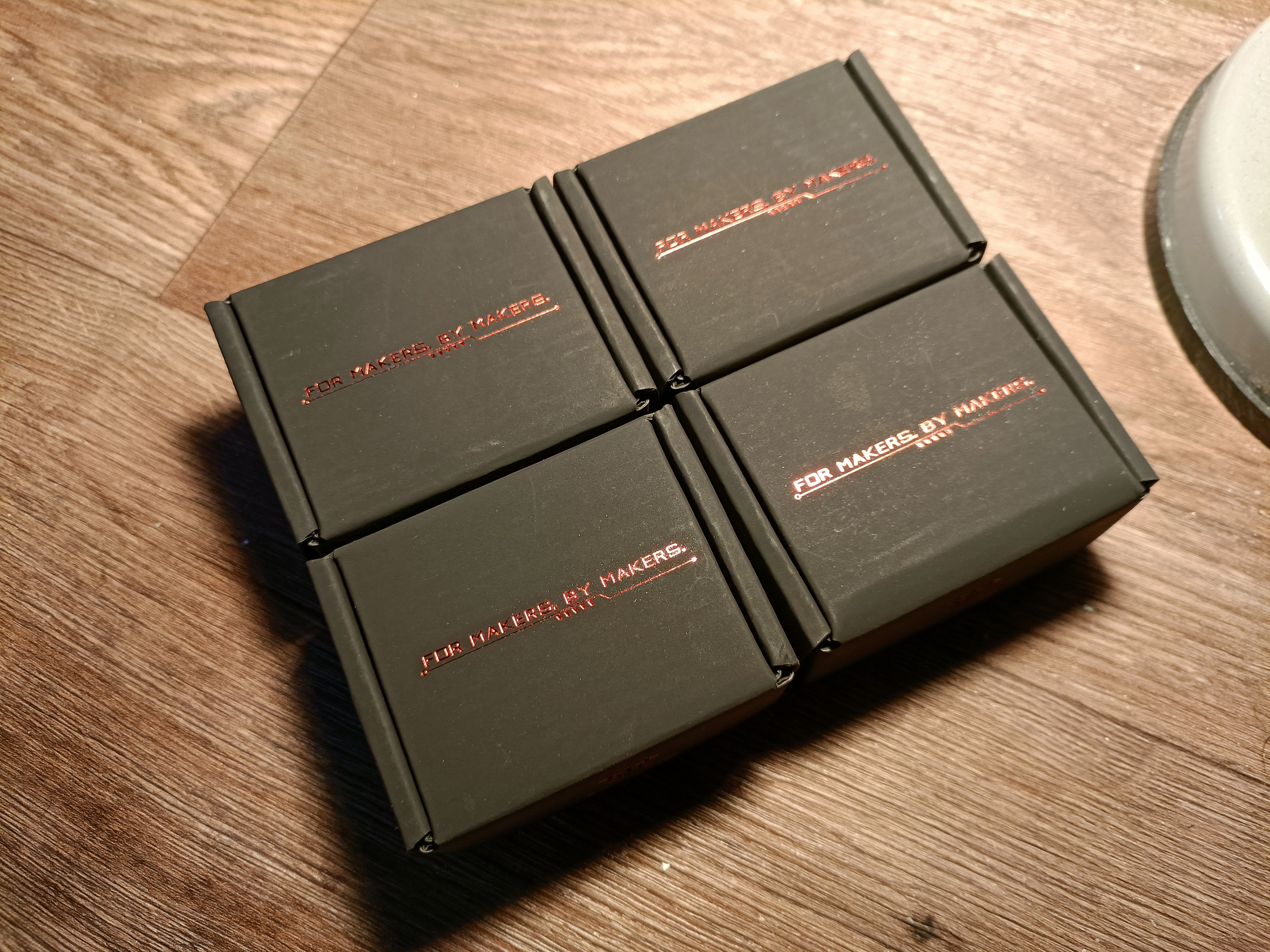
07/23/2022 at 12:32 • 0 comments![]() So I was able to get on the limited edition CB1 drop ($10 price) and, looking at the order speeds in the first hour, I seemed to be the only one that was treating this like a GPU stock drop. I went in with the minimum to grab being 2 (for each Sublime) and 4 ideally (Suspense and a spare) but there was a 1 per customer blockade. I bought 1 immediately, tossed and turned for maybe 20 minutes, and made a second AliExpress account to get another one. Sometime (maybe a day) later I was just scrolling around and the $10 CB1 was back in stock. Strange. There's 2 of them though. And I can check out with both of them? Ok then!
So I was able to get on the limited edition CB1 drop ($10 price) and, looking at the order speeds in the first hour, I seemed to be the only one that was treating this like a GPU stock drop. I went in with the minimum to grab being 2 (for each Sublime) and 4 ideally (Suspense and a spare) but there was a 1 per customer blockade. I bought 1 immediately, tossed and turned for maybe 20 minutes, and made a second AliExpress account to get another one. Sometime (maybe a day) later I was just scrolling around and the $10 CB1 was back in stock. Strange. There's 2 of them though. And I can check out with both of them? Ok then!![]() Wow this board is TINY. Seems to also come with an antenna with adhesive.
Wow this board is TINY. Seems to also come with an antenna with adhesive.![]() I wasn't expecting them to be this small. £23.50 is an expected price considering it's like a CB4 version of the Orange Pi Zero 2, but I'd like to imagine how versatile this could've been if their $19.90 (£17.47) lesser early bird price was the consistent price. What about $15??
I wasn't expecting them to be this small. £23.50 is an expected price considering it's like a CB4 version of the Orange Pi Zero 2, but I'd like to imagine how versatile this could've been if their $19.90 (£17.47) lesser early bird price was the consistent price. What about $15?? -
[R] Continuous tape reinforcement
07/18/2022 at 21:10 • 0 commentsOne of the issues I'm finding with the continuous fibre feature implementation is that the fibres on Aliexpress like basalt and carbon are sold in something that more resembles a ribbon than thread.
![]() While scrolling around, reading what industrial 3d printing companies have been getting up to, I found out that there's some rivalry between Desktop Metal and Markforged, and that Desktop Metal was making a continuous fibre 3D printer that could compete with Markforged's offering.
While scrolling around, reading what industrial 3d printing companies have been getting up to, I found out that there's some rivalry between Desktop Metal and Markforged, and that Desktop Metal was making a continuous fibre 3D printer that could compete with Markforged's offering.Seems that Desktop Metal has engineered a way to use the fibre's ribbon stock to their advantage.
![]() It very much seems to be a 2 tool toolchanger with the fibre tool being able to rotate 90 degrees, which would be able to get the fibre in any orientation. This reminds me of the rotating nozzle I found earlier.
It very much seems to be a 2 tool toolchanger with the fibre tool being able to rotate 90 degrees, which would be able to get the fibre in any orientation. This reminds me of the rotating nozzle I found earlier.![]() It likely uses a heated roller (that seems spring loaded in the animation) to apply the continuous fibre.
It likely uses a heated roller (that seems spring loaded in the animation) to apply the continuous fibre.Why is this a nice solution? For starters, I believe that it could be easier to do this instead of accurately aligning a thread under a nozzle to print a fibre infused extrusion line. Another thing is that it sounds much easier to feed to the Slime, easier to cut and I can use the free extruder gear as the 6th axis, unlocking the ability to have fibre reinforced prints not just on the Rotary Bed, but on all the beds like the Long Bed (because parts that use this bed would likely benefit the most from fibre reinforcement) and 5 axis support.
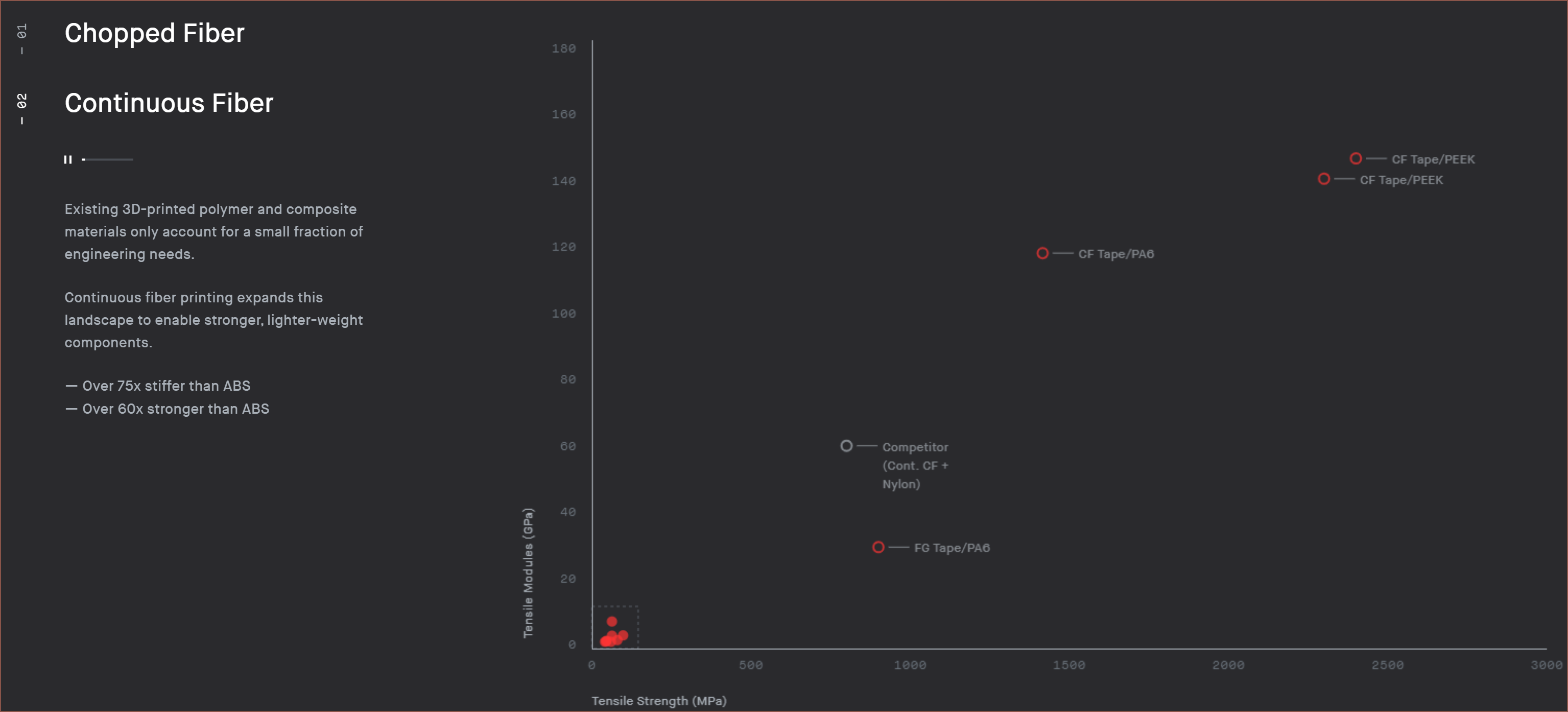
Then there's these 2 graphs:
![]()
![]() The grey dot is likely Markforge's flagship continuous carbon fibre:
The grey dot is likely Markforge's flagship continuous carbon fibre:![]() The carbon fibre tape is nearly 2x the tensile strength and is 2x the modulus. I'm more interested in the cheaper glass fibre tape (for which basalt should be a bit better). 30GPa modulus and a strength inbetween 800 and 1000MPa, according to Markforge's datasheet:
The carbon fibre tape is nearly 2x the tensile strength and is 2x the modulus. I'm more interested in the cheaper glass fibre tape (for which basalt should be a bit better). 30GPa modulus and a strength inbetween 800 and 1000MPa, according to Markforge's datasheet:![]() I just hope that I can just press the basalt fibre into a printed channel similar to using a soldering iron to embed steel wire into a print. If that plan fails, I'd imagine extruding a thin bead of filament on one side of the fibre for a stronger bond between the fibre and the bottom of the channel could provide a solution.
I just hope that I can just press the basalt fibre into a printed channel similar to using a soldering iron to embed steel wire into a print. If that plan fails, I'd imagine extruding a thin bead of filament on one side of the fibre for a stronger bond between the fibre and the bottom of the channel could provide a solution. -
[A] Project Frozen
07/18/2022 at 03:55 • 0 commentsFrozen due to the following reasons:
- Diverting time to the #SecSavr Suspense [gd0105], #Teti [gd0022] and #Tetent [gd0090]. If I try and go for everything, I'll probably end up with nothing to show for it.
- Other than continuous fibre, gd0105 could potentially fufill my 3D printing needs in a smaller footprint and lower cost, as well as higher speed for multiple parts (the brand is called "Second Saver" after all).
- gd0105 and the previous log made me realise just how much more stuff there is to model for gd0036, and I'd like to wait for #enSweepen [gd0096] to model all that.
- I'm out of my student accomodation for the next 2 months, where gd0036 is intended to be installed. I can make gd0105 outside of the SleepCinema, but can't really say the same thing for gd0036 (back to the "smaller footprint" thing I wrote earlier)
I remember I had a slight worry all the way back when I was starting out with gd0036 (in 2021) and thinking to myself "You know I'm not the fastest CAD modeller out there. What if some fancy technology finally comes out in 2022 and makes my FDM printer archaic? I feel like some resin printer could do that if it played its cards right." (similar to buying a 2080ti a month before the 3070). Seems that that time is now. I still can't see how someone or some company before BCN3D hasn't created this kind of film lamination MSLA/DLP 3d printer though. Then again, there doesn't seem to be much research other than on the material side for making resin printers safer to use or cutting out post processing steps.
In other news, I just found out that BCN3D is planning to ship printers in Spring 2023 (as I expected) but only 20 of them (kinda strange, especially since they have over 500 signups and I thought the printers were already ready for mass adoption) so if I could obtain a future where I have a working SecSavr Suspense (as currently invisioned) before then, I'd have a next generation 3D printer before the big companies and it'll be something closer to a second gen version already.
-
[T] SecSavr Sublime Already Out Of Date?!!?
07/16/2022 at 14:34 • 0 commentsThis kinda feels like a "Suffering From Success" kind of thing, but I've been working on the #SecSavr Suspense [gd0105] and returning to my original thought I had a few days after watching BCN3D's VLM video: Is gd0036 redundant/outdated before arival?
Now you may be wondering how a 5 axis, IDEXY, 10 toolchanger, 16 filament, modular bed (with infinite Y belt option), continuous fibre, airtight enclosed, additive and hopefully subtractive 3D printer could possibly risk being old tech already. I'll answer that.
The SecSavr Suspense's current optimistic solution.
I've already mentioned my concerns when it comes to print speeds in this log I just wrote. Sure the Suspense won't be milling PCBs, can only fit 8 materials instead of 16 and probably won't see continuous fibre support, but for additive manufacturing, it has the potential to do what I want out of a printer and has less unknowns with it.
Suspense Unknowns:
- Is there a semi-flexible material that can remove a thin layer of uncured resin and be cleaned before the next layer?
- Can a thin (around 0.1mm) layer of resin be deposited onto a film like PET?
- Can I program a slicer for it?
Sublime Unknowns:
- Can I program a slicer with the below functionality?
- 5 Axis
- Fully independent dual extruder printing
- Continuous fibre pathing
- Milling
- Will the #SecSavr Select [gd0091] be reliable enough?
- Will the rotary axes be stiff enough?
- Will the continuous fibre syringe nozzle be aligned well enough to work?
- Is there a suitable belt bed material?
- Will the magnetic tool system be strong enough for the SecSavr Spindle?
Shared Unknowns:
- Can I make an airtight enclosure with activated carbon (and HEPA for Sublime) filter?
- Can I cool the electronics?
- What's the max speed acheivable?
Moving on, there's material properties. SLA printers can create thermoset polymers, VLM can use less brittle resins and SLA prints are more isotropic, meaning that some parts can be angled to fit where an FDM printer would ideally need a larger bed. Colour choice could also be another win for the Suspense.
With print volume, there's limitations on the Y length (the longest side of the LCD, and maybe the cleaning roller), but as of now, I can't see much limitation for the X or Z height. Gravity is pushing the part towards the bed and not away from it, and in both cases the only thing that really changes is the length of linear rails, ballscrews, roller and the unheated bed. Adding to the fact that resin printers don't need a heated chamber either and the Suspense has serious power savings over the Sublime.
Right now, it's probably too early to call anything and I'm probably just speedrunning through the hype cycle with the new and emerging technology called VLM, but I'm on this rollercoaster now so I might as well enjoy it.
![]()
-
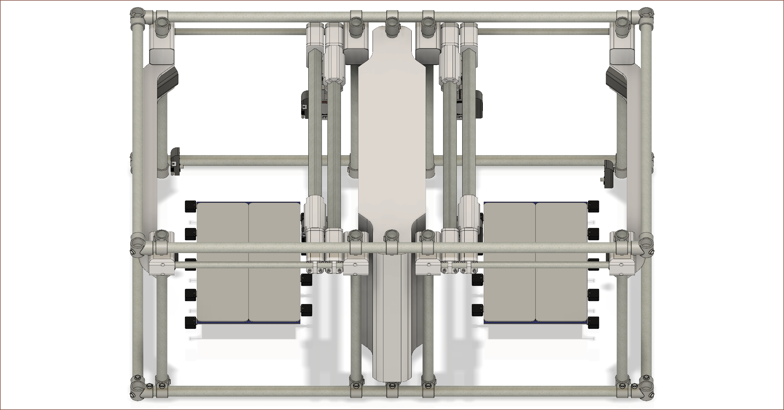
[M] SleepCinema tweaks
07/14/2022 at 04:40 • 0 comments![]() Due to developments with the SecSavr Suspense project, I've moved the Z axis beams closer to the sides of the SleepCinema to make room. I also removed all the extra Slights from the Tool Bar to improve performance.
Due to developments with the SecSavr Suspense project, I've moved the Z axis beams closer to the sides of the SleepCinema to make room. I also removed all the extra Slights from the Tool Bar to improve performance. -
[T] 352 Bearings Needed
07/09/2022 at 18:32 • 0 commentsI was thinking about how the specific implementation of the double belt, wondering if the round profile of the HDT 3M belts would even agree to do what I want to use them for, when I realised that I'd need 8 bearings for each slider that used the double belts. I could probably cut that to 4 if I printed out some kind of wheel, but the total amount of bearings still exceeds the 200 I have now and I don't have that much space in the sliders.
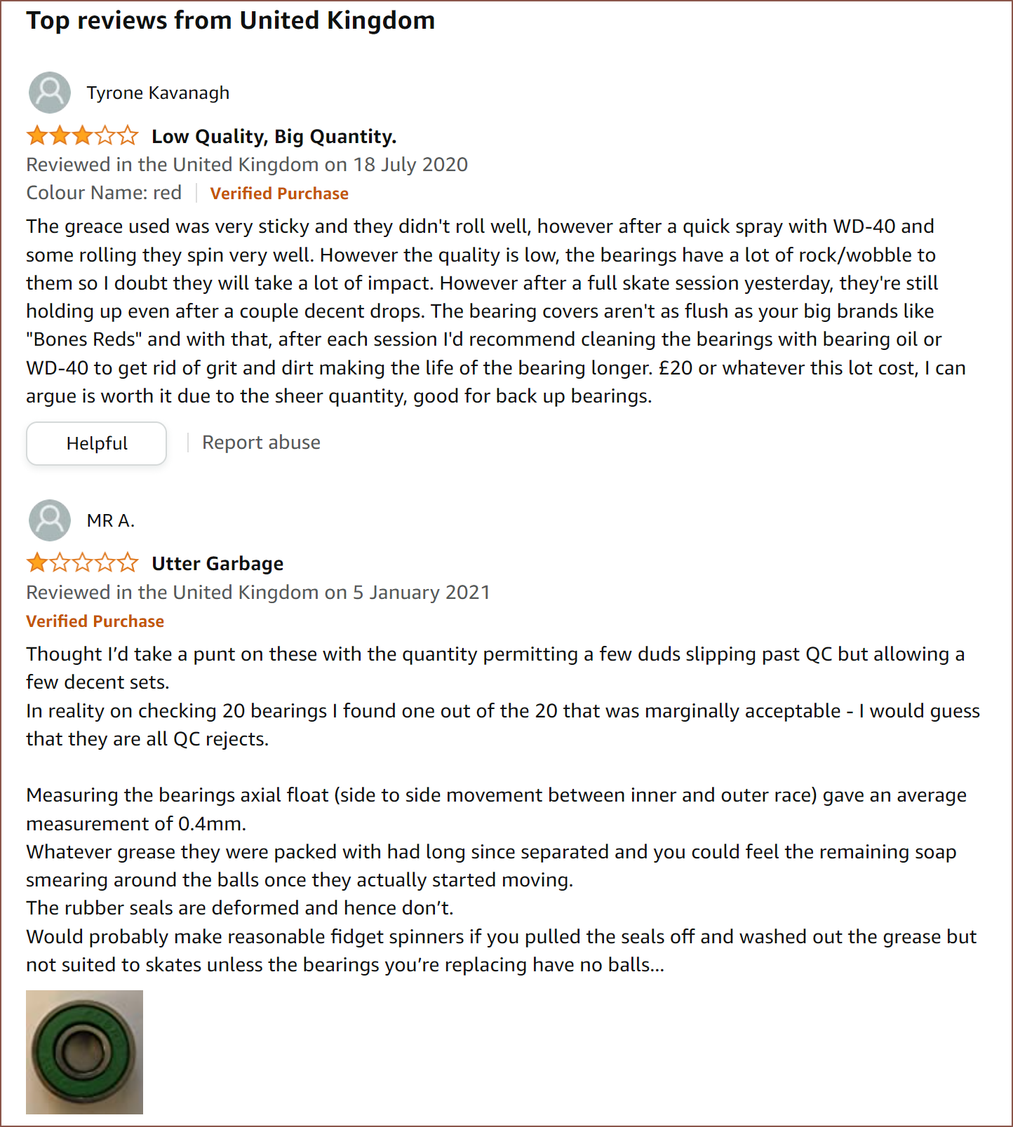
I did the calculations of the main bearings and I got 224 bearings for both Sublimes. I feel like I must've accidentally only calculated for one set in the past. Anyway, it's not like I want to take a chance on a 3rd set of bargain bin bearings that would probably go out of stock forever in the coming months, especially since I'm trying to get some sort of decent system everywhere else (you know, like dual 15mm 3M belts). I don't want the weakest link to be all the bearings, as that's what moves the 3 main axes.
![]()
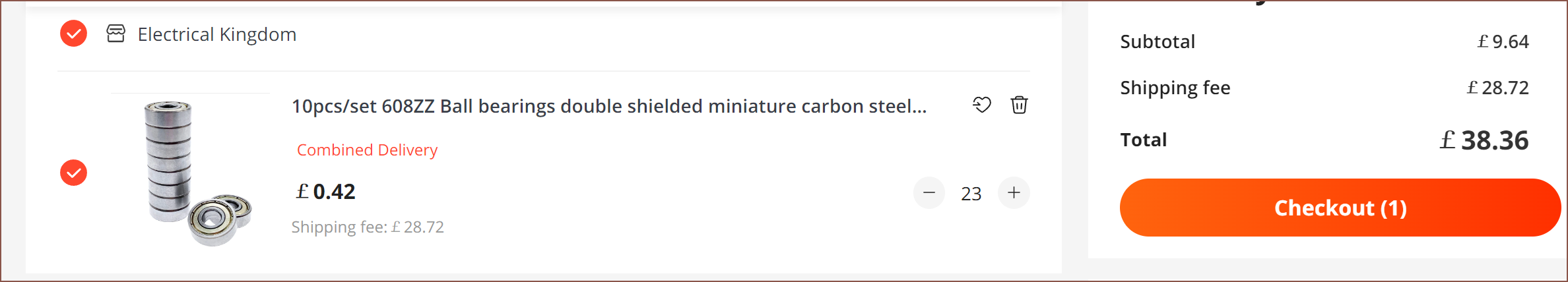
I also didn't know that the seal gap wasn't supposed to be so large. To adress the points about future availability and get something that probably runs better, I found these 608ZZ's on AliExpress.
![]()
No idea about quality, but ZZ bearings allegedly run smoother than 2RS as the rubber seal isn't in contact with the wheels. The ZZ's probably would have a better seal that the RSs I have now. I'm thinking of using the ZZ's for the sliders, and some of the 200 RS bearings will be used in the sliders to squish the double belts together.
-
[E1][T] Multiple use cases for the blower bowden tube
07/06/2022 at 22:04 • 1 commentI reluctantly decided to go for a bowden blower a while ago since I wanted to reduce length. Later, I thought that I could now implement to vacuum for the Spindle, and now I've realised that I could use it as a pathway to send 2.85mm filament down to a modified Slight extruder tool, but more importantly, to move pellets.
It's probably simpler to have some kind of pellet feeder on the Tool Bar, now that I think about it, but the idea was to have a dual tool wide pellet extrusion tool and have 1 bowden blowing cool air to the part and the other blowing pellets.
Yeah it's probably better to just have a pellet refueler on the Tool Bar, high extruder costs and low availability (if purchaser is not a company) nonwithstanding. I did find this awesome pellet extruder that shockingly retracts so well, it sucks filament back INTO the nozzle! I didn't think pellet extruders would somehow get better retract performance than filament ones.
-
[T] Pogo Pinout
07/06/2022 at 09:30 • 0 commentsI've been thinking about the specific pogo connector pinout to see if I can find a solution that won't damage components if the wrong tool was installed. With an 8 channel relay, each Slime will have:
- 24V or Mot1*
- Toggled GND or Mot1*
- GND or CAN1
- Thermistor or CAN2
*Mot2 will be on the other slime.
The first option is the one selected when the relay signal is 0. Pins 1-2 will share a signal pin, as will pins 3-4.
The reasons for the pinout choice:
- Say that the Spindle is expected but the Slight is plugged in. A voltage of +/-36V is applied through Mot1/2. The heater, connected to pins 1 and 2 will see a potential difference of 0V, as will the CANbus tool.
- Then there's the opposite situation, where the Slight is expected but a Spindle is plugged in.
- If a thermistor is used on the Spindle, then the mismatch won't be detectable and pins 1 and 2 will be shorted.
- The Manta M8P seems to have harder-to-replace fuses than the Octopus Pro, so inline replacable fuses would be used instead. Alternatively, since there's not many mentions of installing a thermistor with a spindle, it can be ommited and a MINTEMP error will occur in this scenario.
- Expecting a CANbus tool and receiveng a Spindle will result in a short, so a 9A fuse would be needed anyway.
- Wait a second. What about a diode from Pin2 -> Pin1 inside the Spindle? The Spindle motor will be connected to Pin1 and take current from both pins when operating normally, but 24V to ToggleGND will have a large resistance.
- If a thermistor is used on the Spindle, then the mismatch won't be detectable and pins 1 and 2 will be shorted.
- The next scenario is expecting a Slight but a CANbus tool is connected. The resistance over pins 3 and 4 should be 120 ohms, which seems lower than what a thermistor would have at 300C printing temperatures [reference]. A MAXTEMP error should occur.
- The last scenario is expecting a CANbus tool but a Slight is connected. CAN1 will be grounded and CAN2 would be a 4.7 kΩ pullup to 5V. CAN will tolerate one of the lines being connected to ground [reference].
SecSavr Sublime [gd0036]
An FDM 3D printer that I described as "The FULL Coverage, Extended X, Pro Max, Ultramatrix Solution".
 So I was able to get on the limited edition CB1 drop ($10 price) and, looking at the order speeds in the first hour, I seemed to be the only one that was treating this like a GPU stock drop. I went in with the minimum to grab being 2 (for each Sublime) and 4 ideally (Suspense and a spare) but there was a 1 per customer blockade. I bought 1 immediately, tossed and turned for maybe 20 minutes, and made a second AliExpress account to get another one. Sometime (maybe a day) later I was just scrolling around and the $10 CB1 was back in stock. Strange. There's 2 of them though. And I can check out with both of them? Ok then!
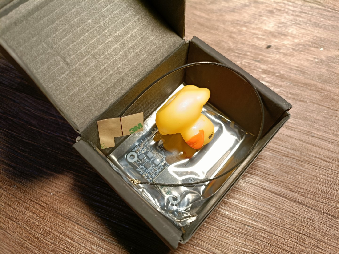 Wow this board is TINY. Seems to also come with an antenna with adhesive.
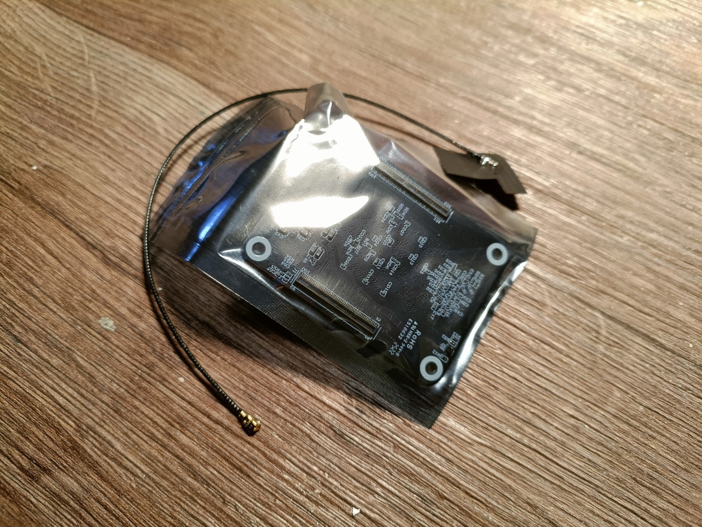 I wasn't expecting them to be this small. £23.50 is an expected price considering it's like a CB4 version of the Orange Pi Zero 2, but I'd like to imagine how versatile this could've been if their $19.90 (£17.47) lesser early bird price was the consistent price. What about $15??
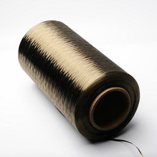 While scrolling around, reading what industrial 3d printing companies have been getting up to, I found out that there's some rivalry between Desktop Metal and Markforged, and that Desktop Metal was making a continuous fibre 3D printer that could compete with Markforged's offering.
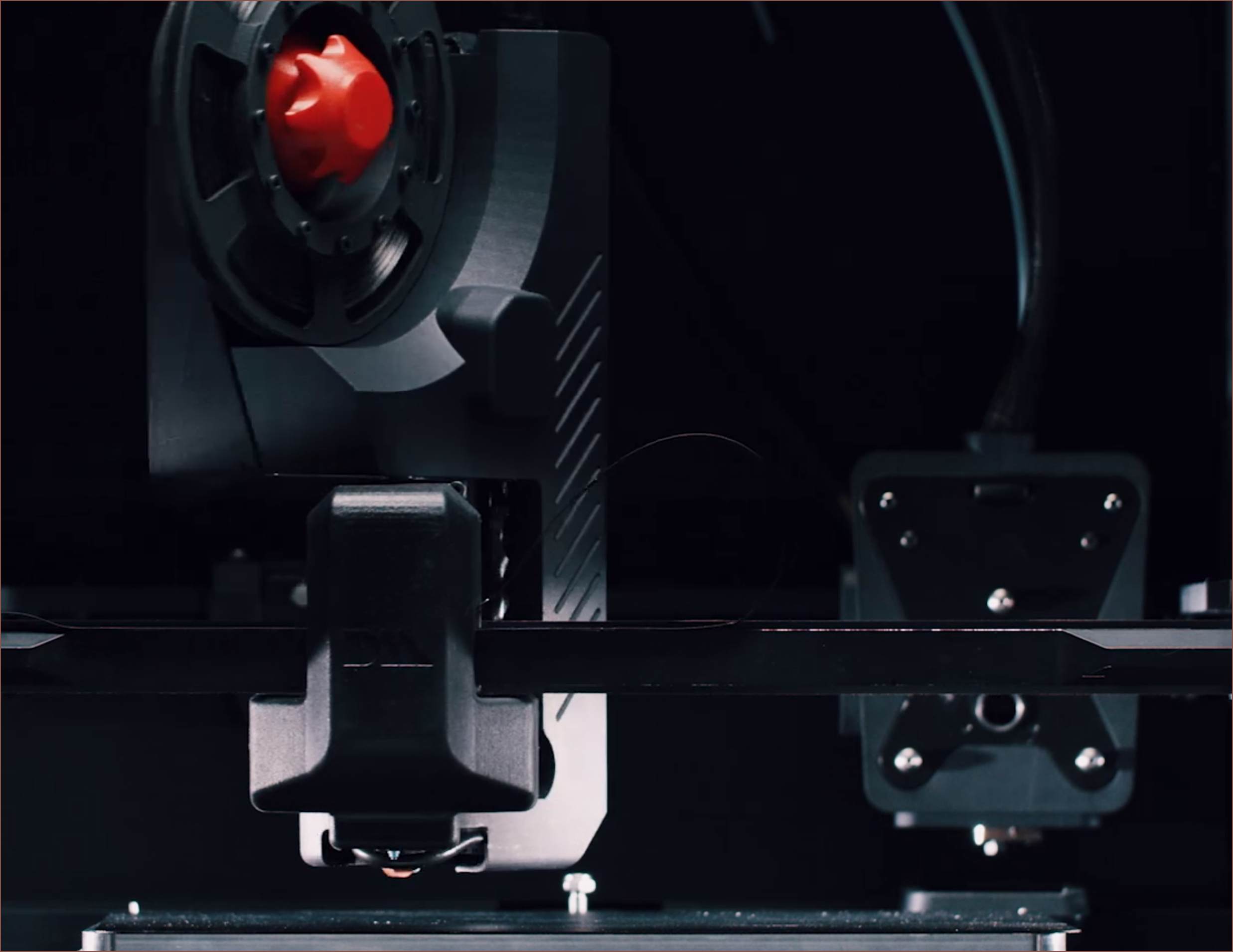 It very much seems to be a 2 tool toolchanger with the fibre tool being able to rotate 90 degrees, which would be able to get the fibre in any orientation. This reminds me of the rotating nozzle I found earlier.
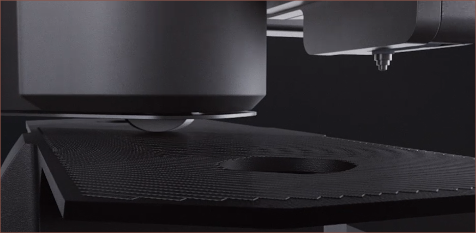 It likely uses a heated roller (that seems spring loaded in the animation) to apply the continuous fibre.
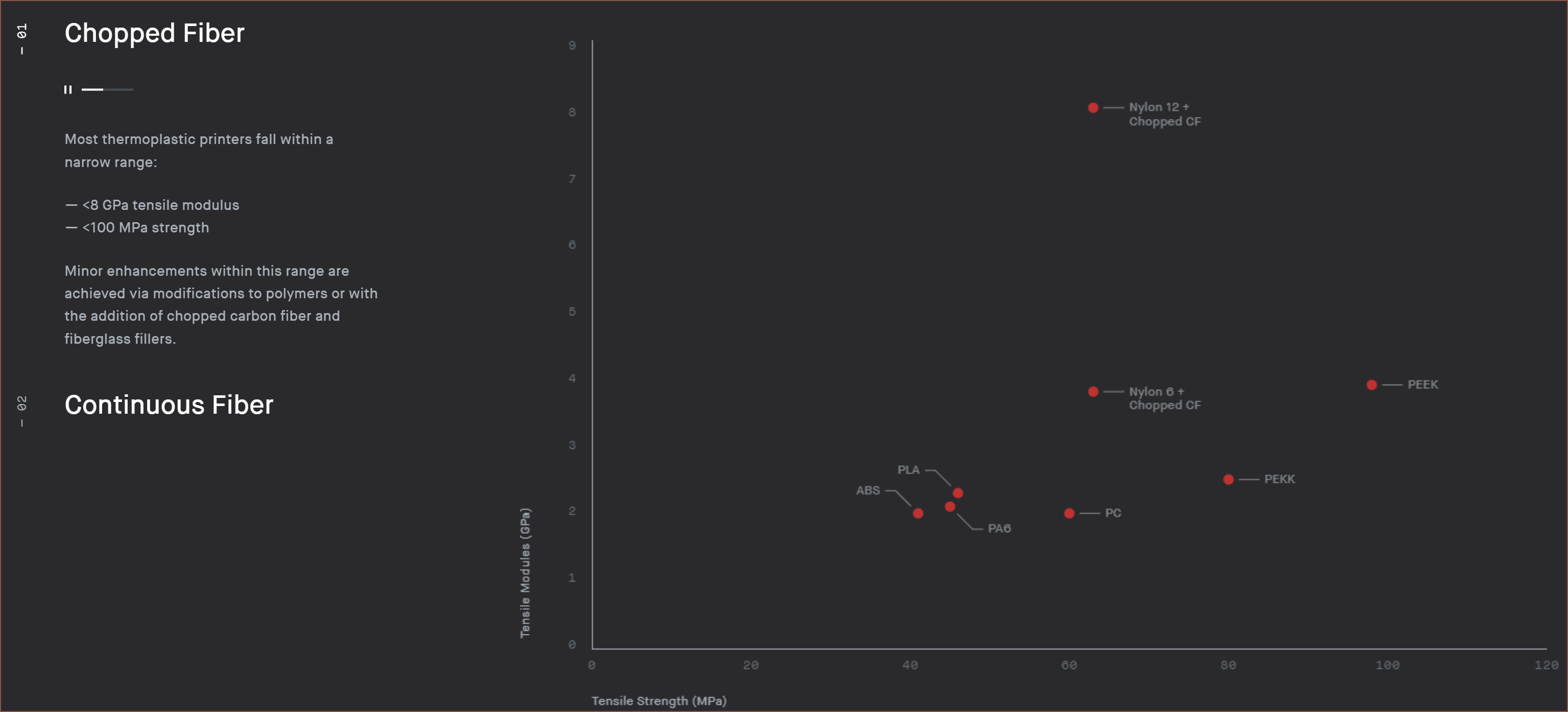
 The grey dot is likely Markforge's flagship continuous carbon fibre:
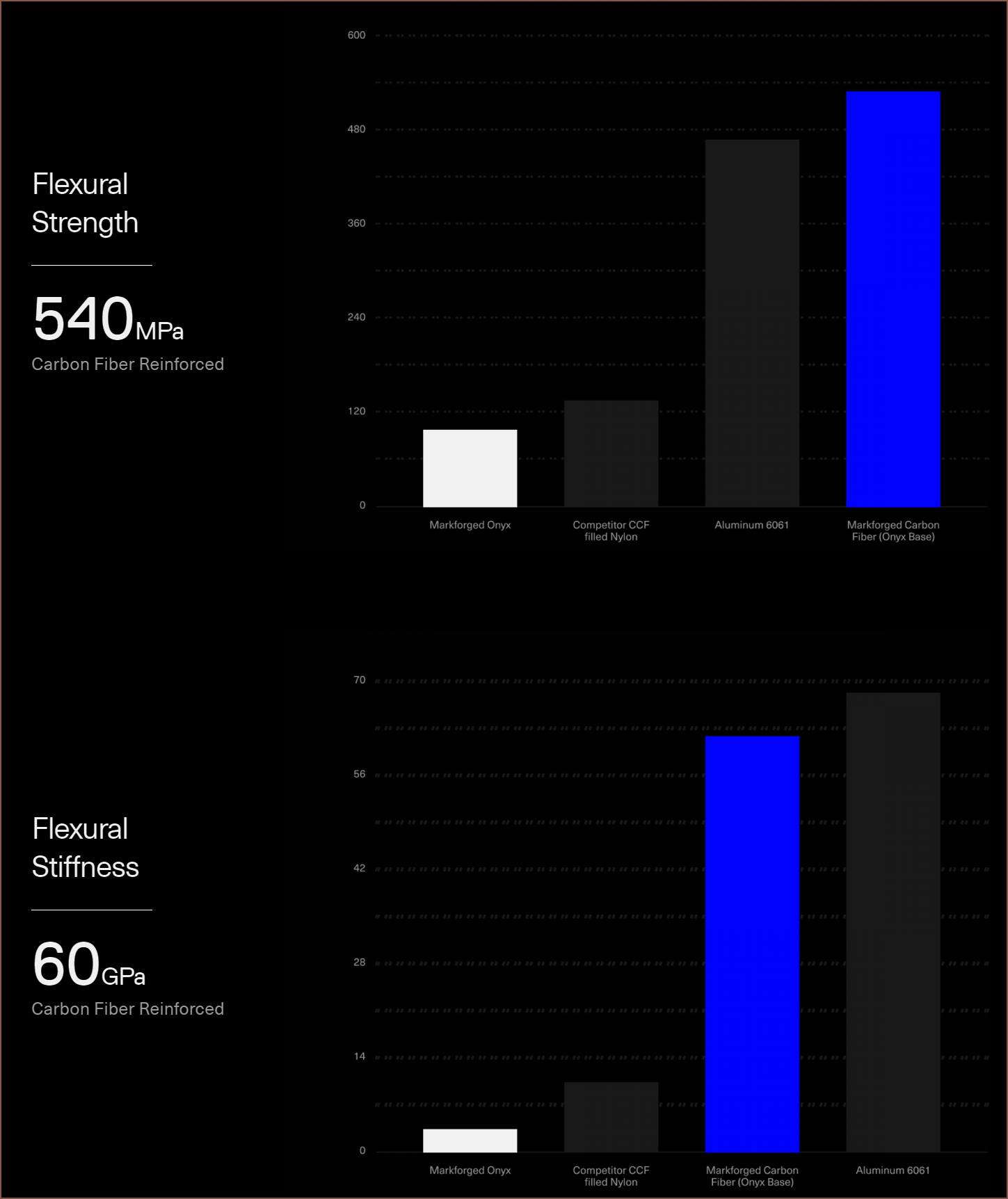 The carbon fibre tape is nearly 2x the tensile strength and is 2x the modulus. I'm more interested in the cheaper glass fibre tape (for which basalt should be a bit better). 30GPa modulus and a strength inbetween 800 and 1000MPa, according to Markforge's datasheet:
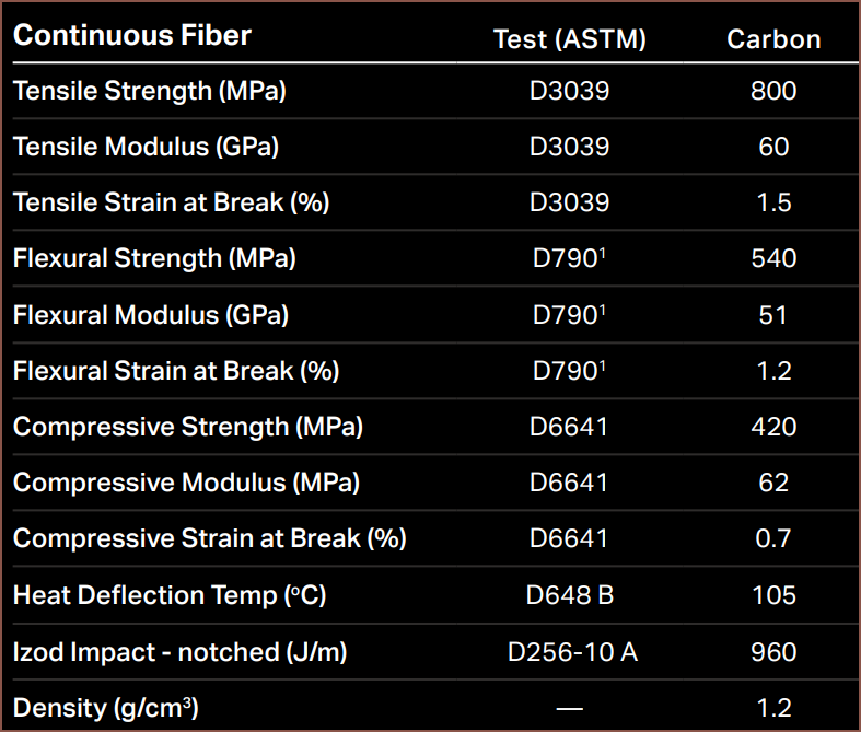 I just hope that I can just press the basalt fibre into a printed channel similar to using a soldering iron to embed steel wire into a print. If that plan fails, I'd imagine extruding a thin bead of filament on one side of the fibre for a stronger bond between the fibre and the bottom of the channel could provide a solution.
 Due to