ElectroBoy
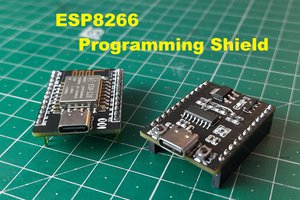
Last week I updated my first version of clone board, And now I am here with a newer and better version. This one performs as original and have more headers to use Male to Female, Male to Male jumpers. So that we can connect sensors directly. This board has a micro USB to program and to give power. So, this is a simple tutorial about Arduino and we will learn, how to design circuit, how to convert this into PCB. Finally order the PCB's from China's no.1 PCB manufacturer "JLCPCB" just in $2 for 5 high quality PCB's.

Some words about my Arduino journey:
It's been too long I am working on this and I have many things to share, which are coming soon. About programs and codes, I can't say anything. I can understand programs but can't write them properly; because most of them are available open-source on WEB. That's why I started with embedded and Now I am designing some compatible microcontrollers, sensors, modules and shields.
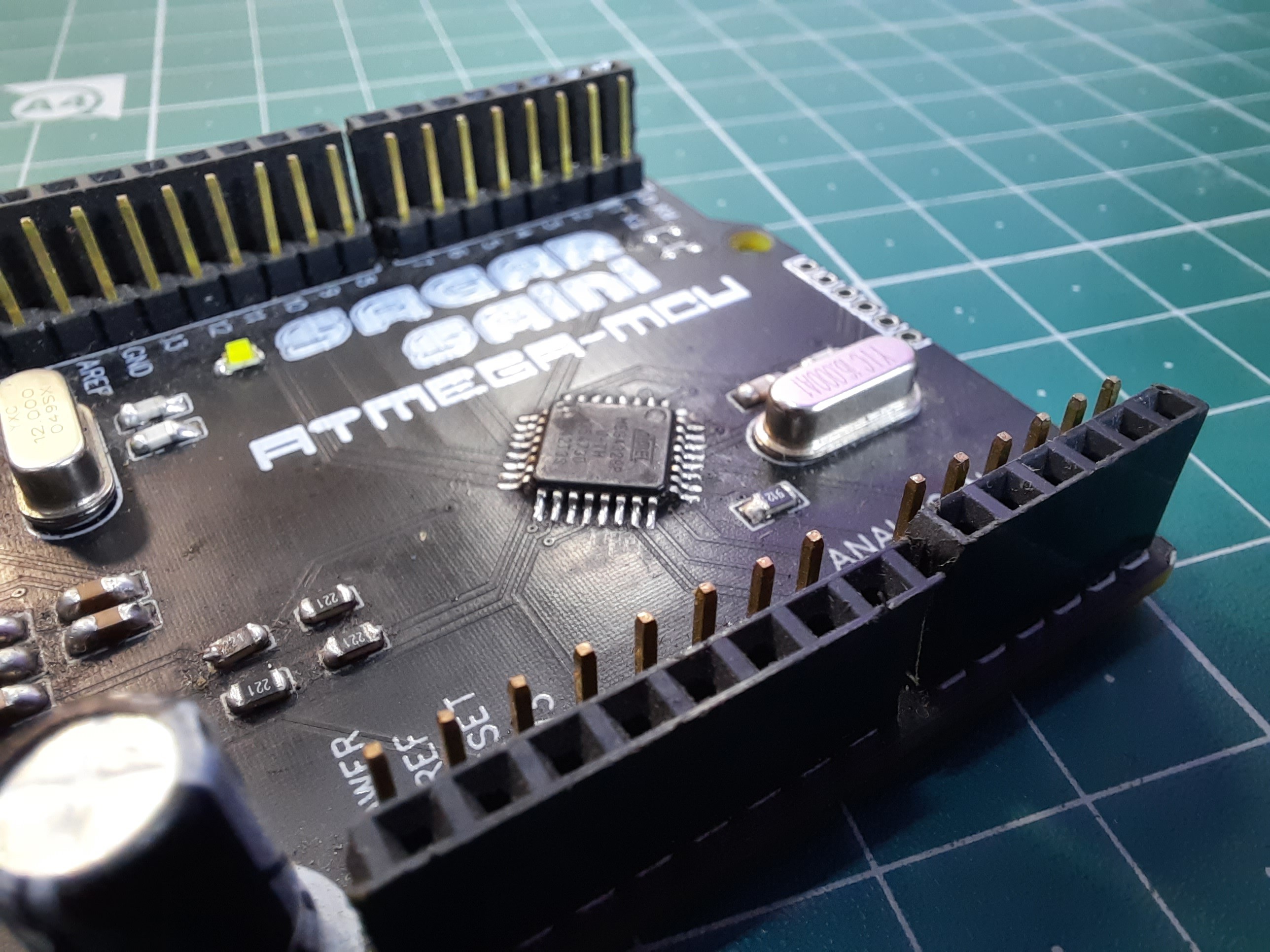
Arduino Microcontroller:
As we know the Arduino UNO's microcontroller(Atmega328p) are basically available in two packages: 28pin DIP and 32 pin SMD. This is powerful enough to get start your microcontroller journey. In this project we are using SMD version, Files of DIP version and PCB layouts are also available see from HERE.

Specifications:
- Microcontroller: ATmega328P
- Operating Voltage: 5V
- Input Voltage (recommended): 7-12V
- In/out Voltage (limit): 6-20V
- Digital I/O Pins: 14 (of which 6 provide PWM output)
- PWM Digital I/O Pins: 6
- Analog Input Pins: 6
- DC Current per I/O Pin: 20 mA
- DC current for 3.3V Pin: 50 mA
- Flash Memory: 32 KB (ATmega328P) of which 0.5 KB used by bootloader
- SRAM: 2 KB (ATmega328P)
- EEPROM: 1 KB (ATmega328P)
- Clock Speed: 16 MHz
- LED_BUILTIN: 13
Designing circuit:
There are some main parts of circuit, First the microcontroller itself. Then a programming chip, some resistors, coupling capacitors, USB port, voltage regulators and crystal oscillator. The schematics is available, Download from here.

List of components:
1) AtMega328p (DIP version)
2) CH340G Usb to TTL (For programming)
3) Micro USB socket
4) 100nF (104) capacitor
5) 22pf capacitor
6) 12Mhz crystal
7) 16Mhz crystal
8) 220-ohm resistor
9) 1k resistor
10) 10k resistor
11) 603 smd led white
12) Pin headers
13) Ams1117 3.3volt
14) Ams1117 5volt
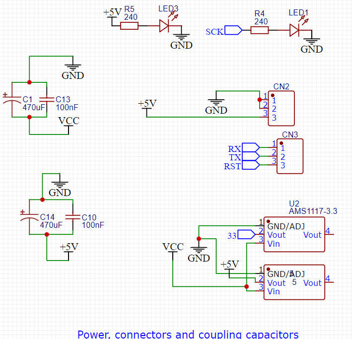
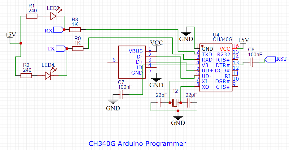
Circuit description:

The most challenging thing is to keep the cost as low as possible, so we tried to go with ch340 programmer chip, which is directly connected to USB and known as USB to serial chip. RX and TX pin is connected to MCU with a 1k resistors and DTR pin to reset with 100nf capacitors. To give a proper clock signal to MCU a 16MHz Crystal oscillator is there with two 22pf ceramic capacitors. Ch340 also need a clock of 12Mhz so there is a separate 12MHz crystal. AMS1117 5v provides 5v to all circuit. Ch340g is used to provide 3.3v or we can use a separate regulator. Reset pin is connected to 5v with 10k resistor and pulled down whenever we have to reset the programmer. Some capacitors are used to reduce the noise in signals and There are 4 indicating led's for RX, TX, Power and D13.
Simplified circuit:

PCB and Designs:
This is my design, I used the same form factor as the Original one. Using the Black color and 1.6mm thickness with HASL finish. Download Gerber from here.

The PCB's is sponsored By JLCPCB and you will get coupons of worth $30 on first signup through my link. https://jlcpcb.com/see
In addition a $5 coupon for 1st PCB order. So register to JLCPCB using this link from here. Also providing SMT assembly, 3d printing and aluminium PCB services.
Soldering and assembling:
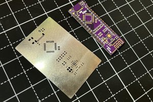
First solder all the smd components, I don't have any special solder, hot plate or hot air gun. so I am using that my simple solder iron with hand soldering method.

Then place all the through hole components and solder them.

Place the headers and finally we are ready to go.
Programming:
Download the CH340G drivers...
Read more »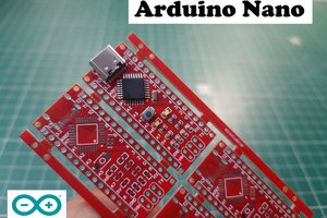
 Lithium ION
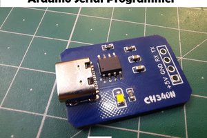
 Sagar 001