 ElectroBoy
It is very difficult to know the voltage of a Zener diode without markings. If the markings on Zener diode got erased, we can’t tell the ratings on Zener without testing circuit and proper equipment. So, today we will make a Zener testing meter to get the voltage ratings of a Zener diode. A simple and accurate meter then we’ll make a case for this.
The testing circuit and Gerber files to the PCB is given below. I am using JLCPCB prototype service to give a professional look to my projects. They are offering 5pcs of 2,4 and 6-layer PCB just in $2.
Concept in brief:
To make a Zener tester, we have to boost-up the voltage to the maximum limit of measuring. Means if you are measuring Zener diodes below 24v then the voltage setting of booster will be 25-28volts). A 10k resistor to protect the diode and the voltage drop across the Zener will tell the ratings.
Pictorial Circuit:
This is a easy to understand circuit with proper wiring and pictures, Provided by cirkit designer software.
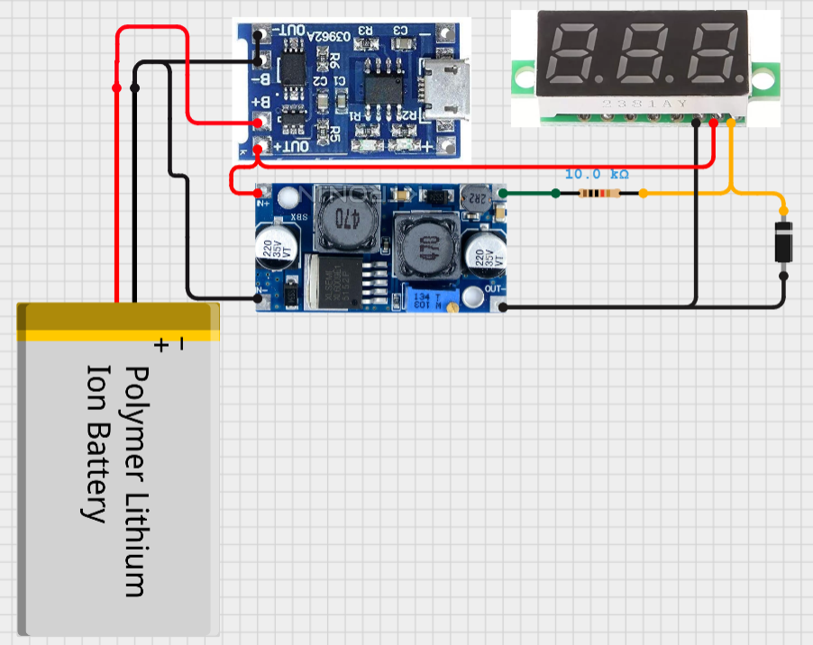
To make this type of detailed circuit diagram with picture presentation, Check our New software "Cirkit Designer" and in next updates of the software we are adding code compilation for Arduino.

Download Cirkit designer from here.
Starting making your presentation more cool and easy to understand. Just move on Cirkit designer. And you will get free access to lot of more project shared in community by top engineers.
Components used:
1) Volt-meter
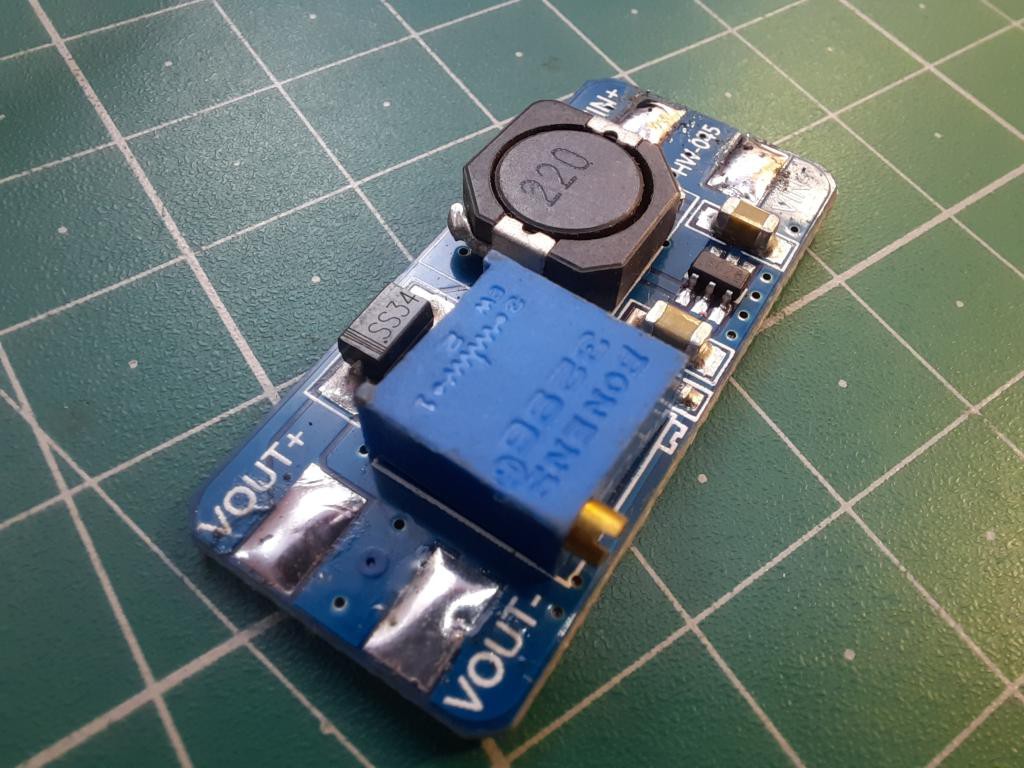
2) Dc-dc booster module
3) 3.7v battery and charging module
4) 10k resistor
5) Clip wires
6) ON/OFF switch
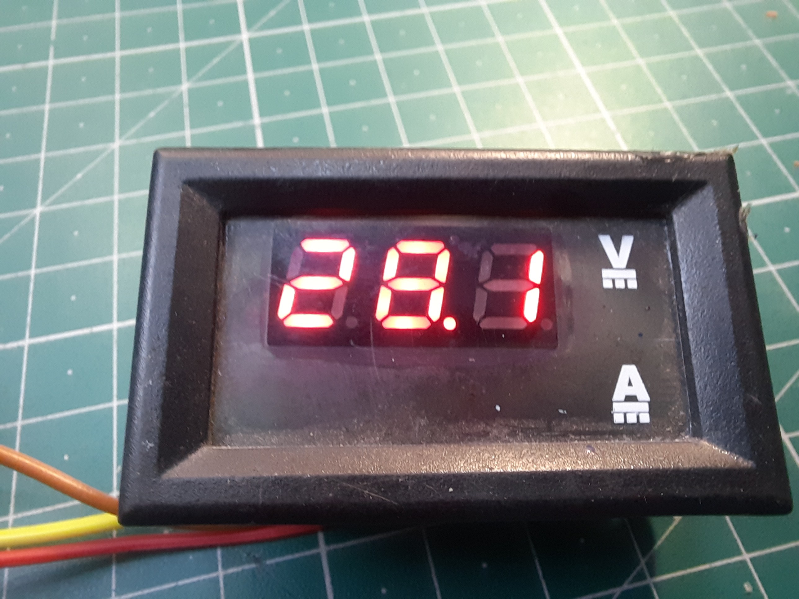
Display for Zener tester:
A simple multimeter can do the job in voltage measuring setting, but for simple and portable project it will be too big. So we need a small multimeter or we can make one using 16x2 LCD. Here is the full tutorial to make a voltmeter using Arduino with LCD.
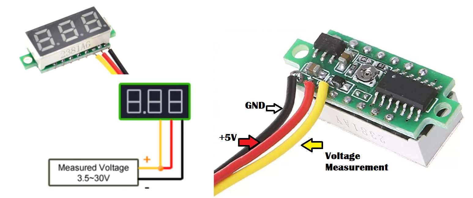
This small voltmeter has 3 wires (2 wires to give power) and one more for measuring. You can buy this type of voltmeter in cheap from Ebay or Amazon.
This small voltmeter has 3 wires (2 wires to give power) and one more for measuring. You can buy this type of voltmeter in cheap from Ebay or Amazon.
Circuit diagram:
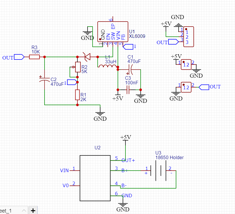
Circuit description:
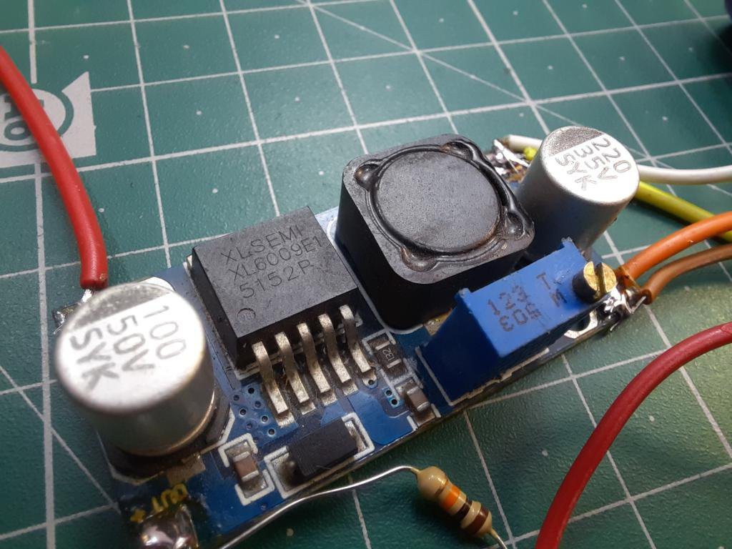
Here we are using XL6009 voltage booster module, with this a 10k resistor to protect the diode and 3.7v lithium-ion power cell. To display the readings either we can use multimeter or separate voltmeter module. This 3.7v lithium battery can be charged using dedicated 4.2v charging circuit.
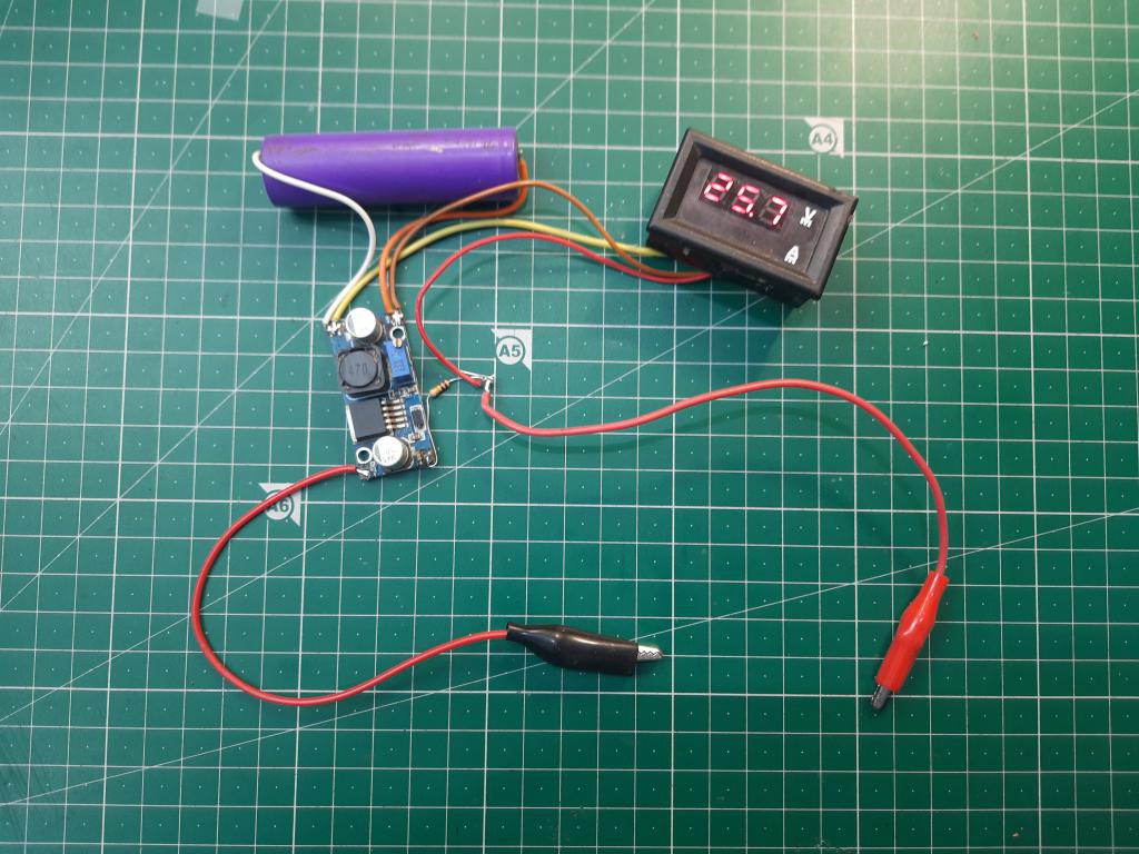
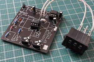
In the above image you can see the circuit out of the box made of wires. This is only made to test the operation. And once done, I made a proper circuit in EasyEda and PCB files are shared below with you guys.
Want to know more about the SMT assembly service of JLCPCB click here.
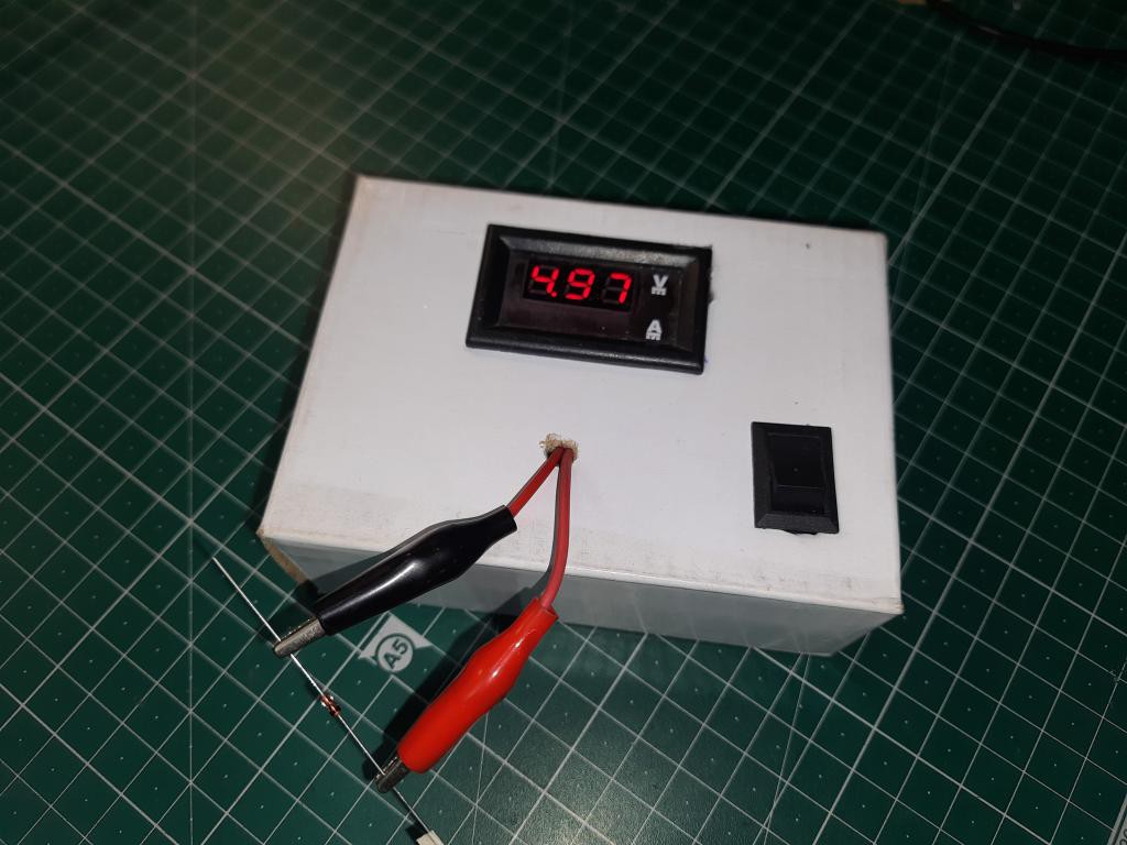
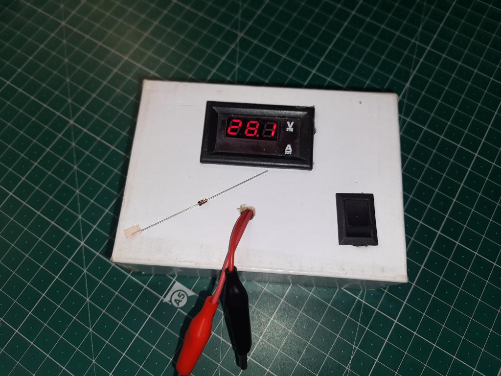
Measuring:
In the circuit I am using XL6009 voltage booster, but the same work can be done using any other module. just max out the output of your voltage booster. if you want to measure the ratings of zener between 0-24 volts, the voltage should be 5-6 point above, say-28 to 30.
Case for Zener tester:
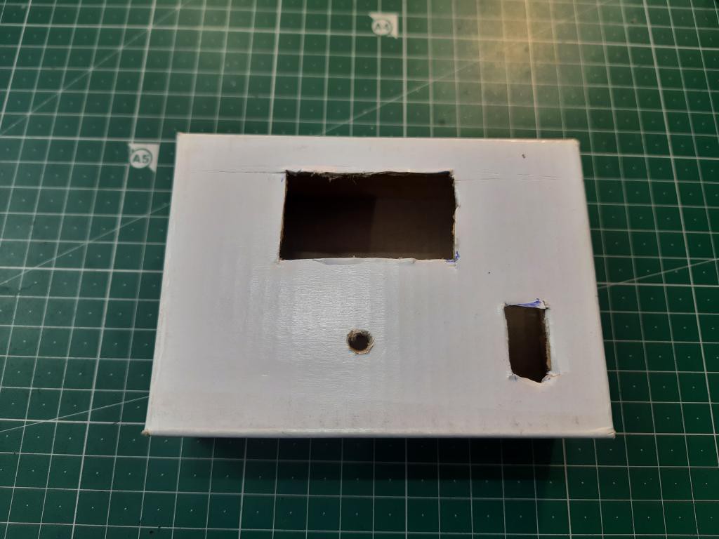
At this moment, I don’t have any 3D printer. I made a case using thick cardboard sheet and insert all the circuitry inside. Although, if you are making it on Pcb prototype then there is no need of any case.
PCB layouts:
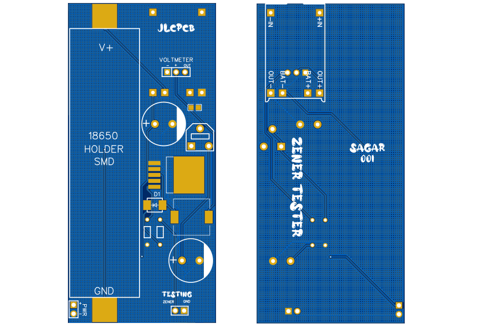
Download Gerber files from here. Sign-up to JLCPCB using this link and get 4 discount coupons worth $27.
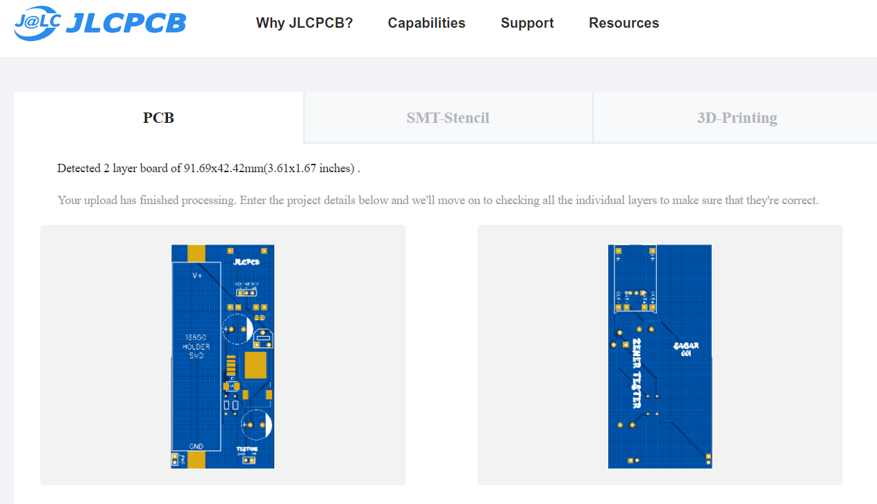
Ordering Process JLCPCB:
JLCPCB offers a very good method to order PCB, You don't have to remember the size, just upload you Gerber file and software will automatically detect the size.

Then choose the color, thickness and other parameters like surface finish and gold fringes.

Then checkout just in $2 and you will receive a good quality branded boards just in 7 days.
Follow me on Hackster, Instructables and Hackaday. Try our Limited custom PCB making service just in $2 and order them from JLCPCB
 555Techlab
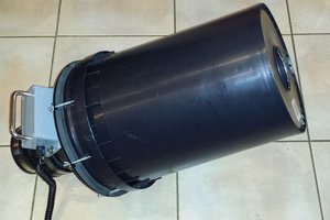
 Robert Hart
 KSUdoubleE
 Sagar 001