 555Techlab
Description:
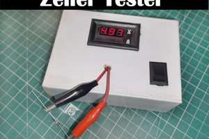
This project is a useful voltage reference for analog circuit experiments and a cool project for analog circuits enthusiasts. With this project you are able to provide a voltage reference in the range of 0.00 to 9.99 VDC.
The project is designed on a PCB. On the top layer of the PCB you will also find the circuit diagram.
Circuit:
The circuit of the adjustable voltage reference is designed as a simple opamp circuit - an inverting amplifier with a old style LM741.
An opamp (IC1) s amplifying a reference voltage of -6.2V.
The reference voltage is created with a 6.2V-zener diode (D1).
The feedback resistor of this inverting amplifier circuit is the pushwheel switch with integrated resistors which works as an adjustable resistor from 0 Ohm to 9.99 kOhms.
A +12V/-12V power supply with the ICL7662 provides the power for the opamp.
The input voltage is +12V DC.
PCB:
I designed a simple PCB. On the black PCB I placed the components including the circuit diagram of this project.
Pushwheel Switch:
A pushwheel switch is a mechanical switch with 10 positions (0-9). The output signal can be in decicmal or BCD code. In this project we need 3 decicmal pushwheel switches.
Each pushwheel switch includes a resistor circuit on a smal PCB in order to get a adjustable resistor in the range of 0 to 9.
The range of the single pushwheels are.
1.digit: 0-90 Ohms (9 resistors with each 10 Ohms)
2.digit: 0-900 Ohms (9 resistors with each 100 Ohms)
3.digit: 0-9000 Ohm (9 resistors with each 1000 Ohms)
All three pushwheel switches in serie result in a adjustable resistor with a range from 0 Ohms to 9990 Ohms. See pushwheel switch circuit diagram.
You can also use a 10 turn potmeter with 10K instead the 3-digit pushwheel switch.


 ElectroBoy
 Sagar 001
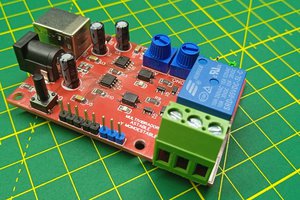
 ElectronicABC
An improvement of this is to take the feedback for the zener diode directly from the output of the opamp, and that is a common circuit for 30+ years or so. This way, the zener diode has a constant current (through a resistor from a constant voltage) and thus the zener voltage is independent of the input voltage of the circuit.