Lithium ION
Home theaters and speaker systems are very popular due to Bass songs, releasing everyday and I am very fond of music and songs. I want to buy one for me but I don’t need commercial one. Because I have a much deeper knowledge in analog/digital amplifier designing. So, I want to design a low power consuming and high efficiency circuit my own.
I used to design transistors amplifier but for a home system it is too big. Transistor amplifier are mostly used for high output and they are little bit noisy too. I need a super quite and HI-FI stereo circuit. Then I found the datasheet of TDA7265 audio amplifier IC.
TDA7265:
The TDA series of IC’s are very popular for their high-fidelity sound and super quite operations. There will be no humming or external noise if this IC is paired with proper external components. I am using TDA7265 which is a stereo IC, give the extreme output of 25watts per channel. TDA series need a very fewer external components too. But these class AB amplifiers are also need a cooling system. In most of the cases heatsink can do the job without any active cooling(fan).
Features:
I want to mention one thing here, TDA7265 need dual channel power supply. And this is possible only with transformer. As mentioned in the datasheet the maximum power voltage is 18-0-18. Therefore full power output and better efficiency same ratings transformer is required.
- Mute options
- Thermal Overload protection
- Stand-By feature
- Short circuit protection
- High output power (25W at 8ohms speaker)
Components required:
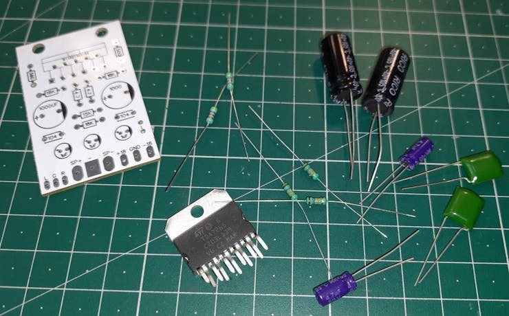
1) TDA7265
2) 18K resistors
3) 560ohms resistor
4) 4.7ohm resistor
5) 100nf capacitor (Polyster film)
6) 1000uf capacitors (Electrolytic)
7) Custom PCB from PCBWAY
Circuit diagram:
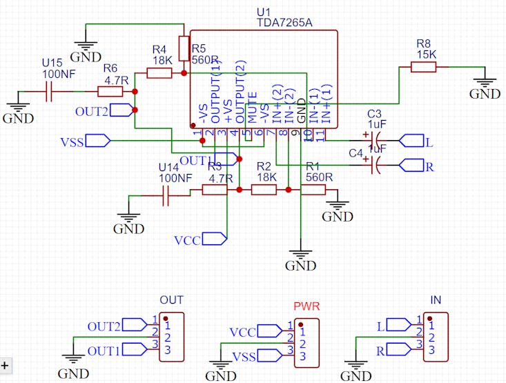
I found this circuit in datasheet and this is real application circuit. Then I made my own with to understand it better. This IC is of 50watts, either we use 25watts for two channel for stereo operation or 50watts in bridge mode. The circuits for bridge mode is available here.
Moving to professional looks:
My circuit is complete but I want to give professional look to my project. So I designed the PCB to make the form factor as small as possible. A big shoutout to PCBWAY to sponsor this project. I upload my designs on PCBWAY.com offering best service in low prices. Ordering process is quite simple.
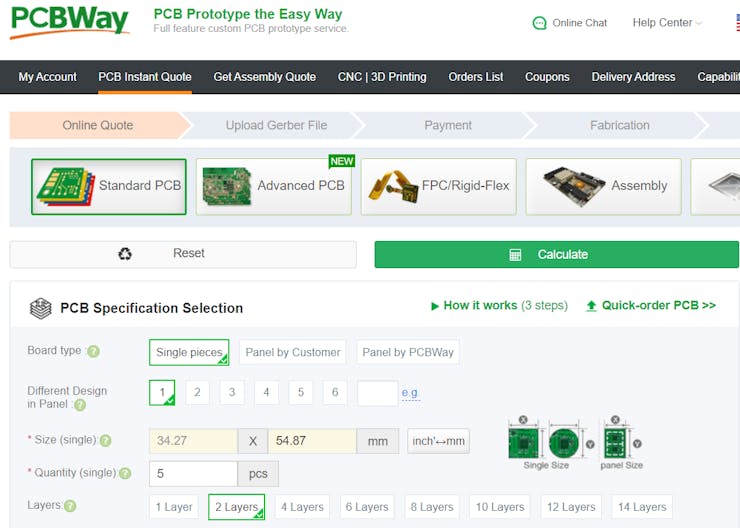
Go to PCBWay > Fill the size of board > choose color and finishing > save it to cart > upload the Gerber files > checkout and make payment.
Mt special link for Sign-up is here, if you register using this PCB discount coupons will be credited into your account. Enjoy the service of 5 professional looking PCBs just in $5 with PCBway.
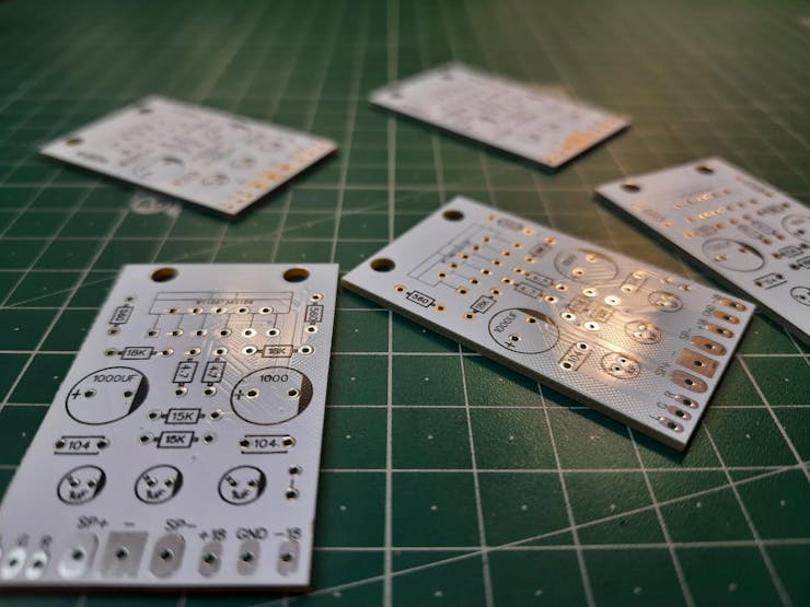
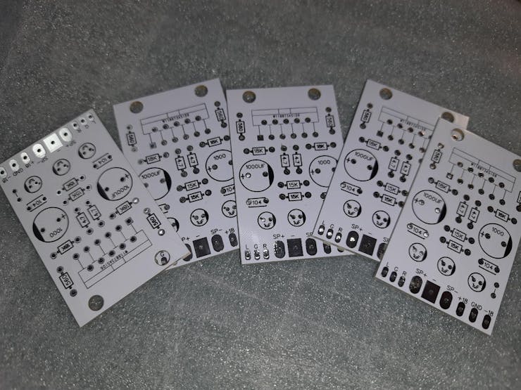
PCB layouts:
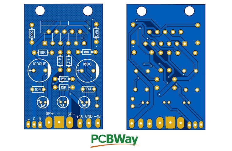
These are PCB layouts I received after 1 week, the quality and surface finish is too good. I choose white color for my PCB, but there are a lot of options you can try from here. Download the PCB Gerber files from here.
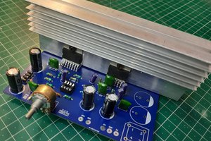
Assembly:
Our design only contains through hole components, DIP IC, resistors and capacitors. So first of all start with the IC and resistors, It is easy to place components after placing small sized resistors. Then move on Big capacitors and other circuitry.
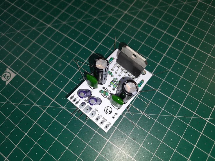
After placement of all the component, bend the legs of all so that when soldering they don’t fall. But first we will cut all the bended legs so that there will be no any dry soldering.

Clean the PCB with propanol or petrol after soldering to remove residual flux.
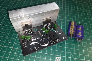
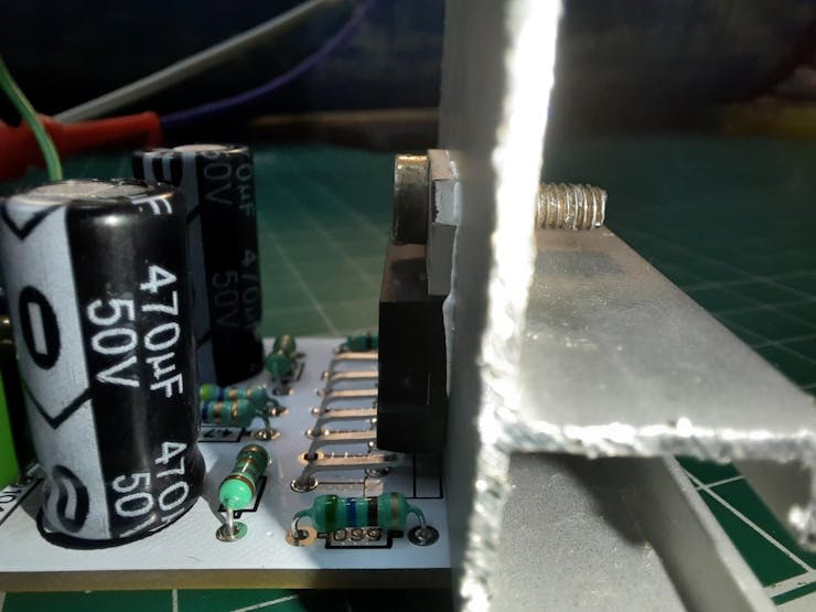
Mounting Heatsink:
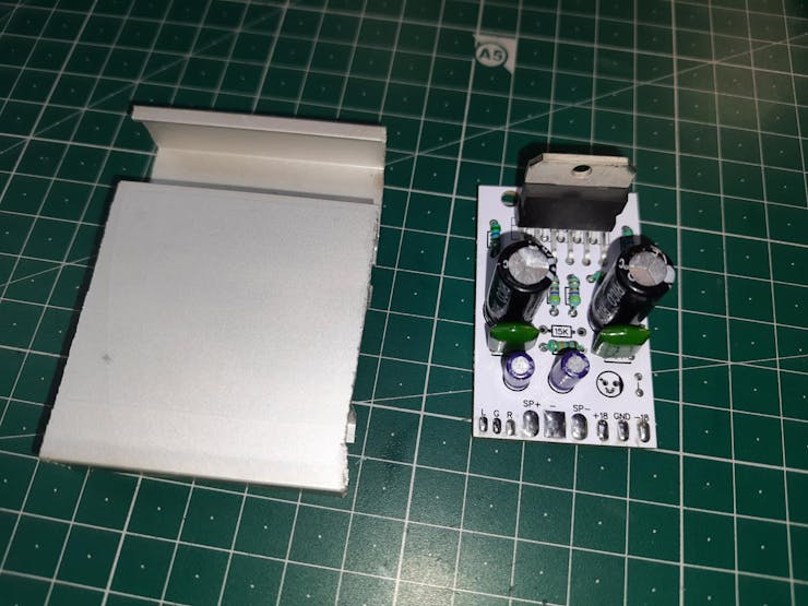
Usually the heat sink, is depend on the area and thickness of aluminum. I am using a big 100mm heatsink with this single IC of thickness 2mm. The most important thing is that there should be no any space lest between the heatsink and IC. To transfer heat immediately from ic to heatsink, we need heatsink compound. Improper placement of heatsink will immediately burn the IC and components.
If you have a...
Read more »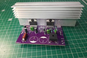
 ElectroBoy
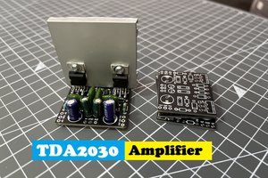
 Sagar 001