Close
0%
0%

Life Time

Hacking an analog clock to display a life

Similar projects worth following
On a normal clock, one second is a second in real life. On this clock, one second can be 20 hours. When all of these extended seconds add up, the clock takes a century to complete one midnight to noon cycle. Of course, the clock can count any other duration greater than 12 hours (think weekend, vacation, a whole year) just as well. If the clock is being used to display someone's life, 00:00:00 represents their birth, and 12:00:00 represents an estimated death.

Why?

I wanted to waste less time, so I thought having an at-a-glance view of my life would be a pretty good motivator to stay focused. Obviously, I can't know when I'll die, so I set the clock to complete its cycle 100 years after my birthdate. I liked 100 years because it seems optimistic, but even at that rate the second hand ticks once every 20 hours.

However, I don't expect to always keep the clock displaying my life. I think I'll also use it for shorter time frames, like the week-long spring break I am currently on. The clock could also display a countdown to an anticipated event, like a holiday. 

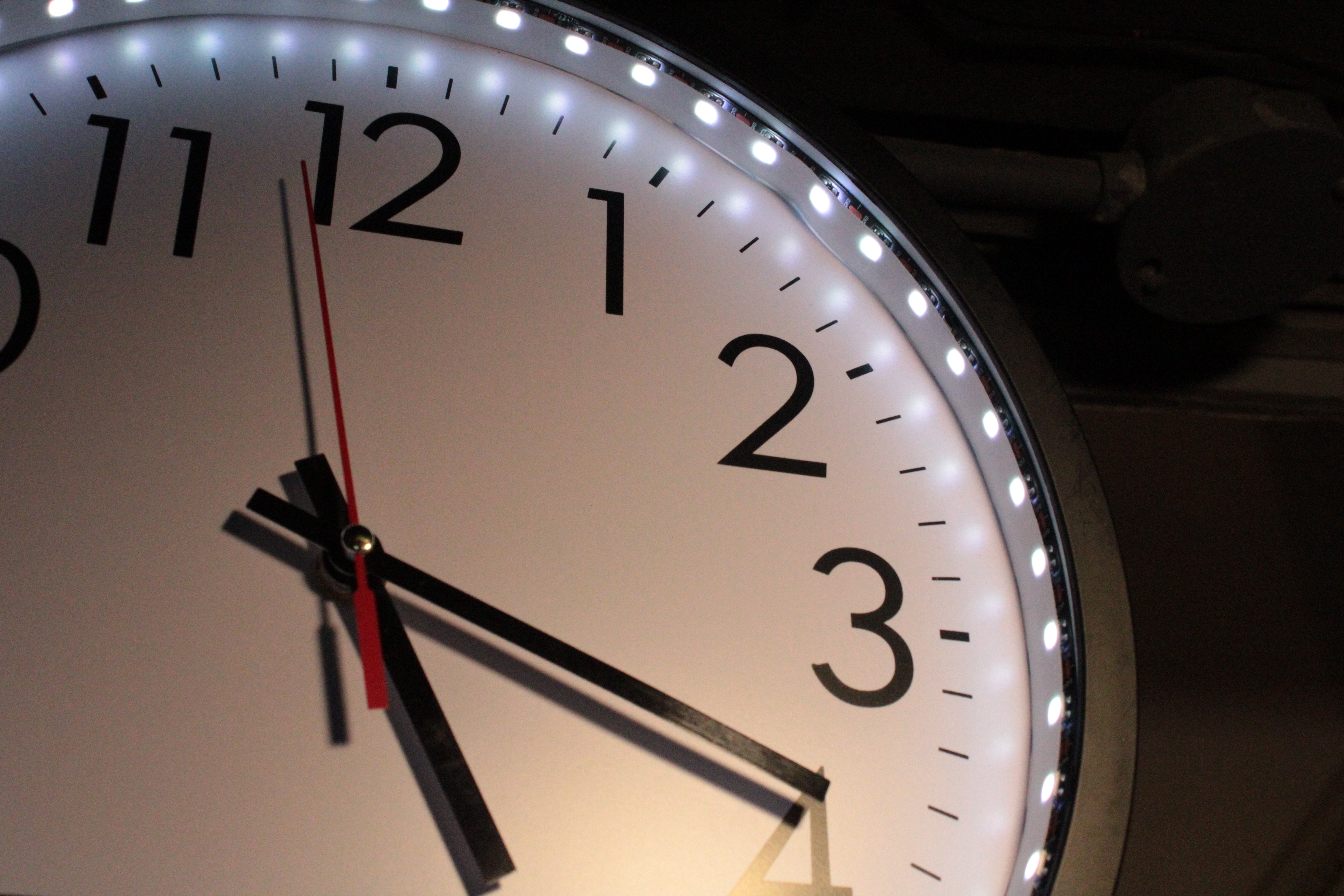
I chose to hack an analog clock for this project, rather than using a digital display for two reasons: first, that it is able to blend in as a "normal" clock (better without the LEDs) and second, it shows the time passed as well as how much time remains. The second reason is important to me because it gives the viewer a sense of perspective of the past, not just what lies ahead.

What:

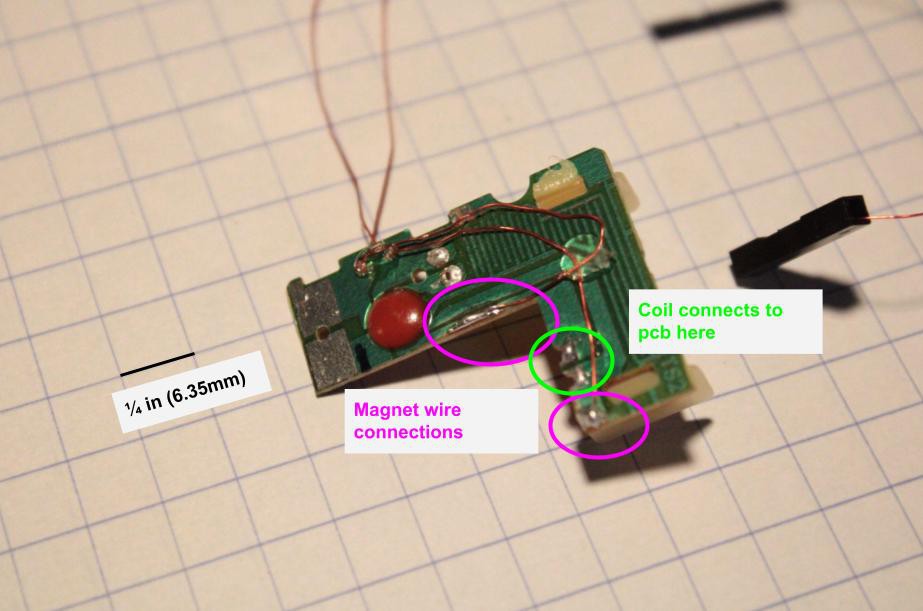
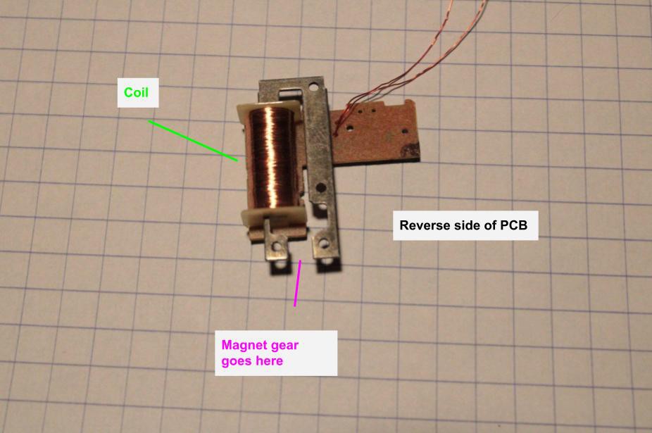
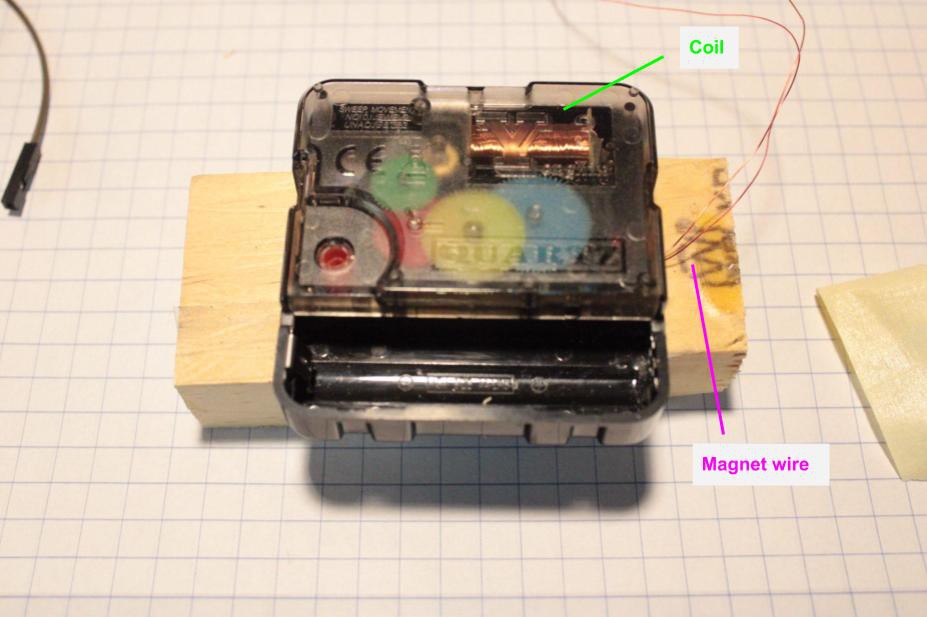
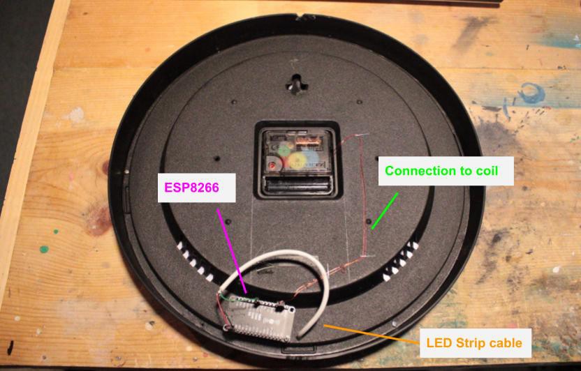
The clock is a cheap analog wall clock I got on Amazon. I removed the glass pane so that it would be easier to change the time on the clock to set it to a different time period. The heart of this project is an ESP8266 development board which gets time data from an NTP server. The ESP8266 steps the clock's internal motor on an interval determined by the time period being displayed. The time period can be changed with a simple serial interface, and the clock can be recalibrated in the same way. Also, a strip of RGB LEDs is attached surrounding the clock face to add light or maybe do some special effects in later versions...

esp8266 mount.step

Glue the flat side to a surface on the back of the clock and attach your board with screws

step - 29.16 kB - 03/29/2022 at 14:35

Download

  • How it works

    Henry York03/29/2022 at 14:10 0 comments

    In my most recent design for this project, the clock's hands are moved by pulsing the clock's internal motor directly with a GPIO pin on the ESP8266. I was inspired to go with this method by this video: https://www.youtube.com/watch?v=XzXfadQXRn8. I soldered two thin pieces of magnet wire to pads on the clock PCB that connect to the coil on the board. 

    When the direction of current through the coil is switched back and forth, it spins a small gear with a magnet on it that drives the rest of the gears in the clock's movement. 

    When reassembled, the clock movement looks like this:

    The clock movement fits into the back of the clock, and the completed control system looks like this:

  • Clock prototypes

    Henry York03/29/2022 at 13:45 0 comments

    My first two ideas for controlling the clock were: to keep the clock's circuit entirely intact and just turn its power on and off with a GPIO on the ESP8266, or to remove the crystal and provide a wave from the microcontroller at a frequency based on how slow I needed the clock to move. The first idea did not work well because the movement of the hands with a one second pulse of power would vary unpredictably, making the clock very inaccurate. The second idea worked considerably better, but required more work from the microcontroller as it had to be putting out a wave constantly. It also lost accuracy pretty quickly. So, I went one level deeper into the clock and bypassed the internal circuits entirely, controlling the clock's motor directly from the microcontroller. 

  • Stepping clock coil directly?

    Henry York03/28/2022 at 16:27 0 comments

    So far I have been controlling the clock by pulsing the pads on the PCB where the crystal oscillator used to be. The ESP8266 board I am using to control the clock sends a square wave into the PCB with a frequency based on the amount of time it is set up to display (a life, a year, a weekend...) It seems to work pretty well, but I think accuracy could be increased by stepping the clock in a different way.

    Inside the clock is a coil that when pulsed, steps the internal gearing of the clock. By connecting GPIO pins on the ESP8266 directly to that coil I should be able to control the clock's movement with better accuracy, especially over longer periods of time. 

View all 3 project logs

Enjoy this project?

Share

Discussions

Similar Projects

Does this project spark your interest?

Become a member to follow this project and never miss any updates