|
|
Mode switches |
Function |
||||
| # |
Set |
Level
| Single Rep |
Slow |
Description |
Action when pressing a TRIG button |
| 1 |
Set |
- |
- |
- |
Set the INACTIVE level for each channel |
Toggle the INACTIVE level of the channel |
| 2 |
Run |
Level |
Single |
- |
Output static levels |
Change output to ACTIVE level while TRIG is pressed |
| 3 |
Run |
Level |
Rep |
Slow |
Square wave, 50 % duty cycle. Repetition period: 2 seconds. (f = 0.5 Hz) |
Fire a single ACTIVE pulse when TRIG is pressed |
| 4 |
Fast |
Square wave, 50 % duty cycle. Repetition period: 10ms. (f = 100 Hz) | ||||
| 5 |
Run |
Pulse |
Single |
Slow |
Slow (1 millisecond) pulses on demand |
Pressing TRIG restarts the waveform |
| 6 |
Fast |
Fast (1 microsecond) pulses on demand |
||||
| 7 |
Run |
Pulse |
Rep |
Slow |
Train of overlapping, slow pulses (PW = 200 μs).
|
TRIG sets start channel of the pulse train |
| 8 |
Fast |
Train of separated, fast pulses (PW = 1 μs).
|
||||
Comments to the mode table
minimum interval between pulses is 75 ms. (No matter how fast the trigger is tapped.)
The toggle switches are also debounced.
Modes 3, 4, 7 and 8 waveforms restart when entering these modes. Flipping the Set/Run (or Single/Rep) switch thus
provides a crude synchronization method.
Square waves (mode 3 & 4) are just slightly out of sync when entering these modes. The square waves are started in
channel order with around 2 μs between consecutive channels.
Pressing TRIG in mode 3 or 4 restarts the square wave for the channel involved. The start level is the channel’s
ACTIVE level. (For the “fast” square wave, all you can hope to accomplish with this is some random phase shift.)
The phase shifts between channels in mode 3 & 4 are not remembered after switching to another mode.
Pressing TRIG in mode 7 or 8 will immediately restart the pulse train with the (new) start channel first. This is always
the case, even if the start channel doesn't change its level.
The start channel for mode 7 & 8 is remembered when switching to another mode.
In mode 7, only neighbour channels have overlapping pulses. There is guaranteed to be a small gap (1-2 μs) between
e.g. the end of the pulse in channel 0 and the start of the pulse in channel 2. (Channels 5 and 0 are neighbours if
channel 0 isn’t the start channel.)
All times are approximate. Timing is performed in software and is subject to small amounts of jitter.
Behaviour when keeping one or more TRIG buttons pressed while changing mode in undefined.
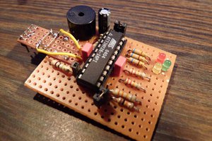
Please visit the project web site (link to the left, below images) for a full description, including schematics and source code.
 Klaus Dormann
 Electroniclovers123
 Michael Wessel