-
Preliminary results
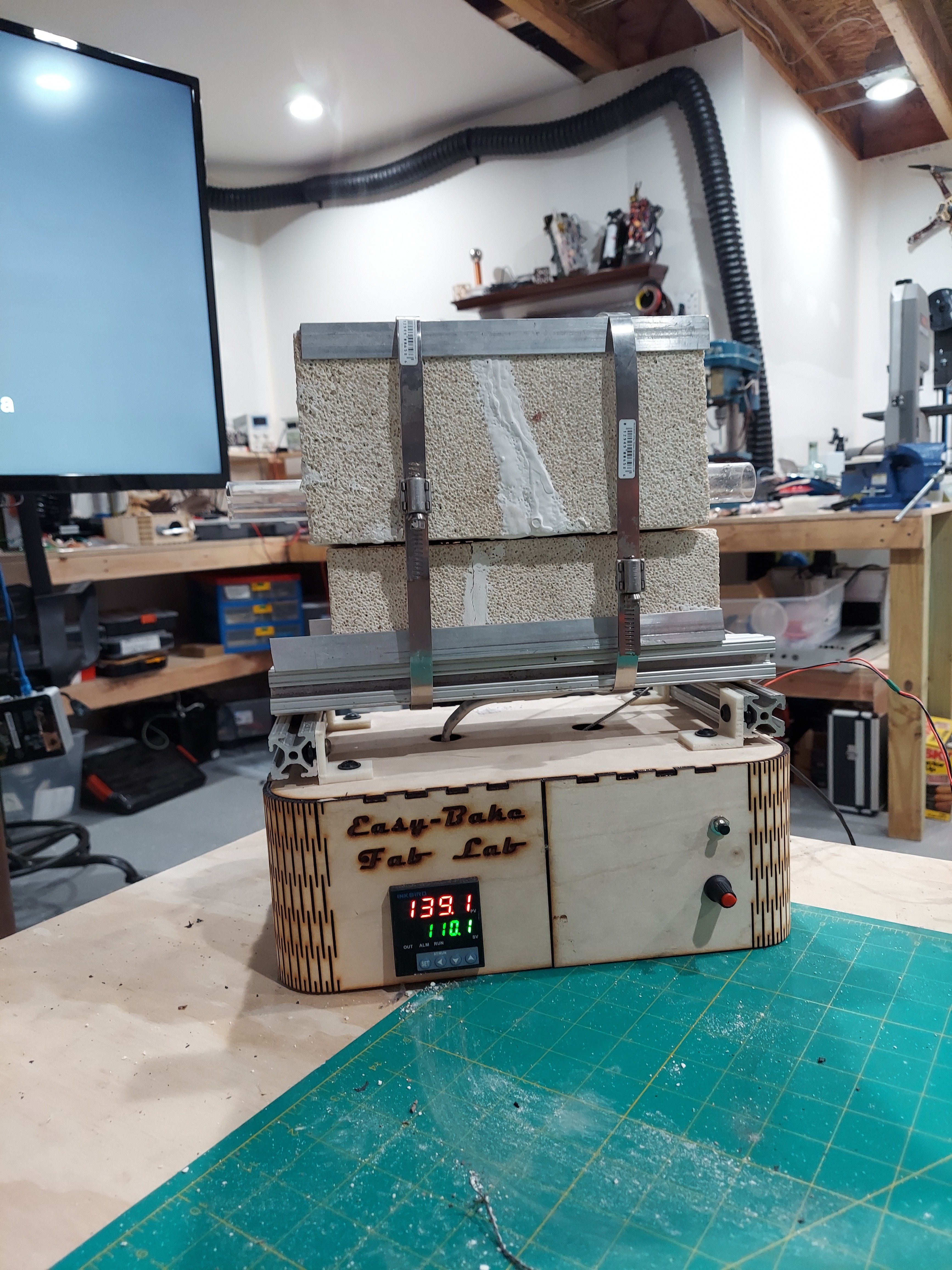
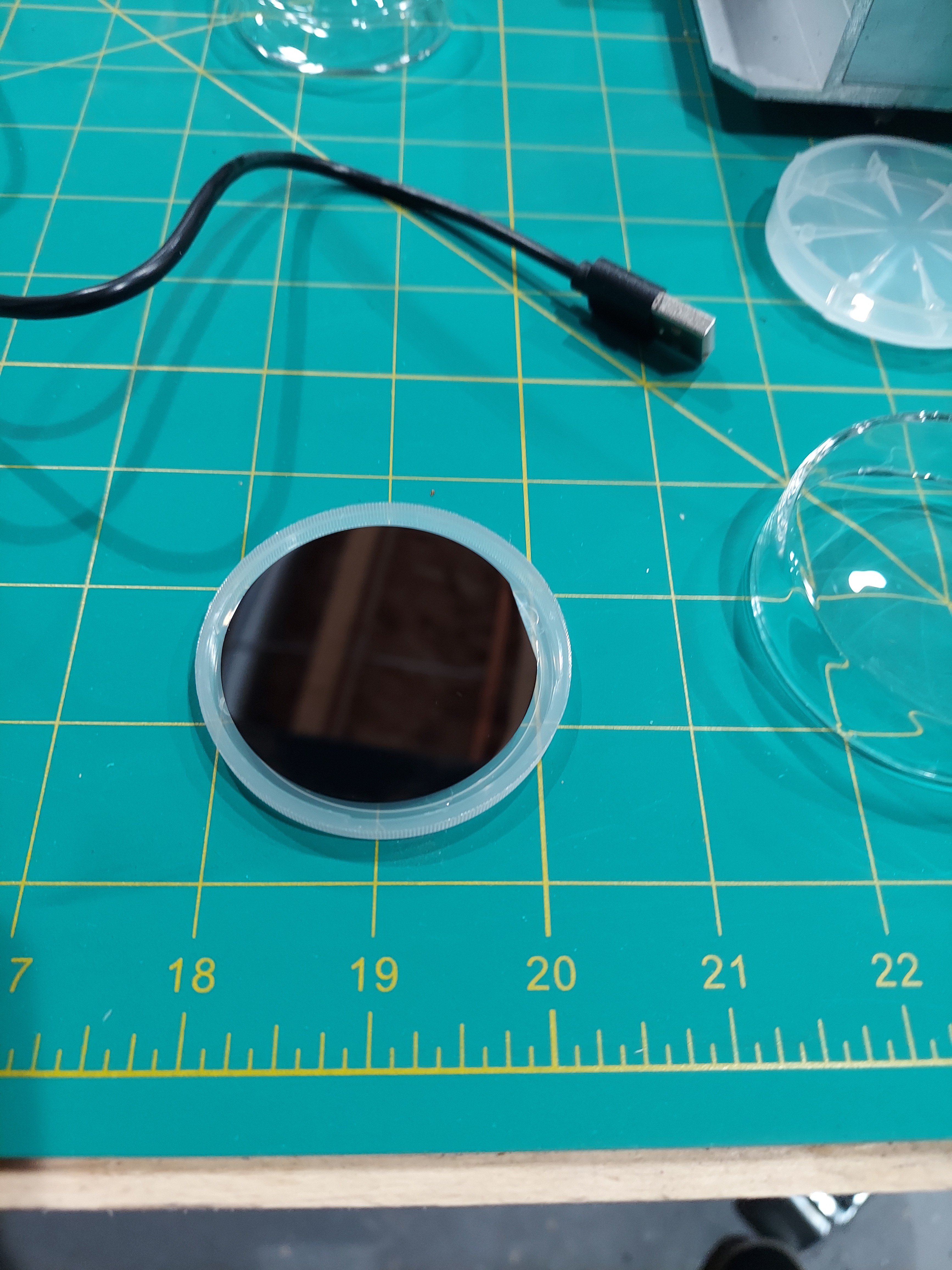
07/04/2022 at 23:02 • 0 commentsSo after I got my Easy-Bake back in working order, I started experimenting with building actual devices. Previously - I worked though growing oxide layers, doping materials, masking, etching, and spin coating.
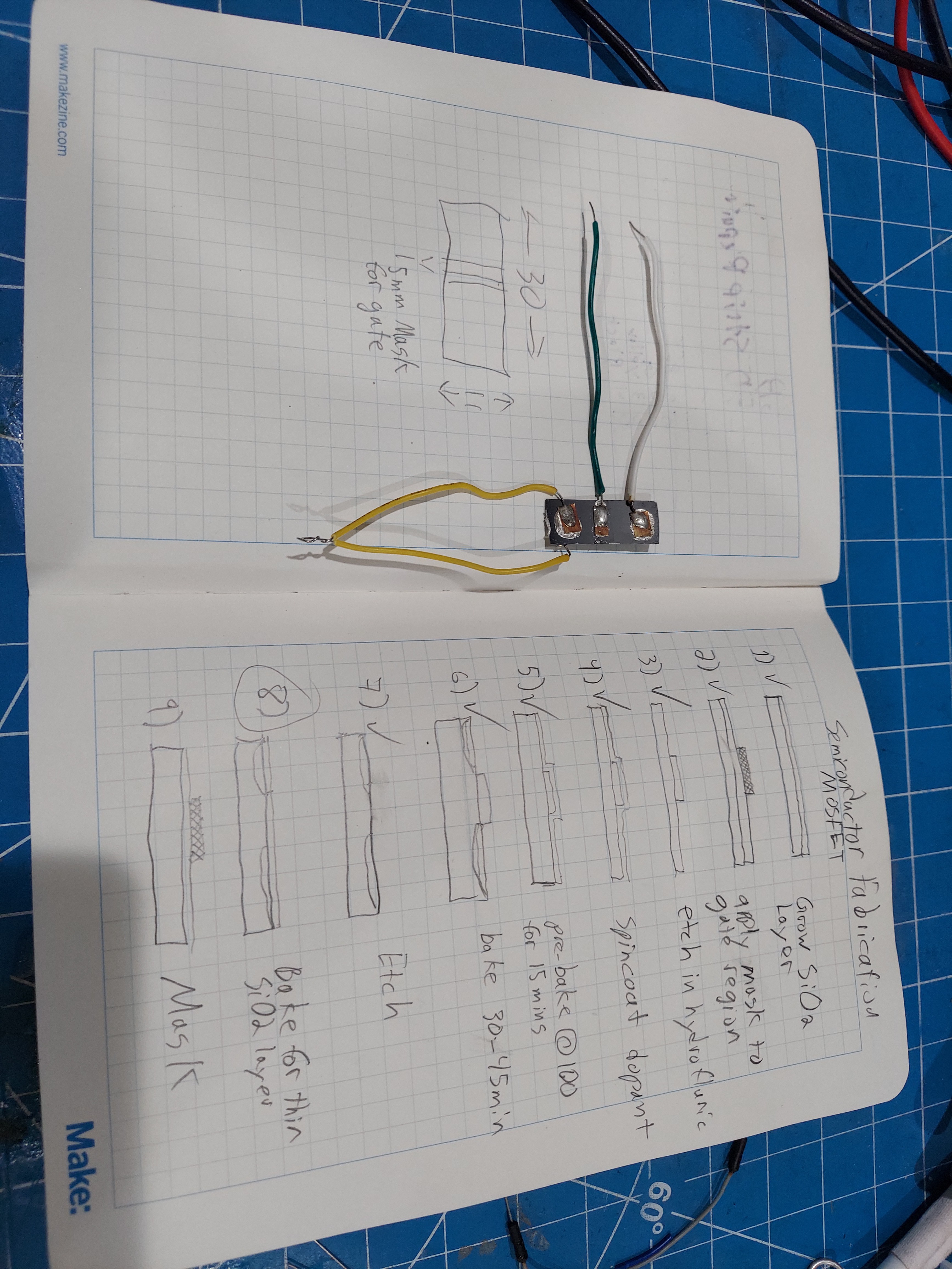
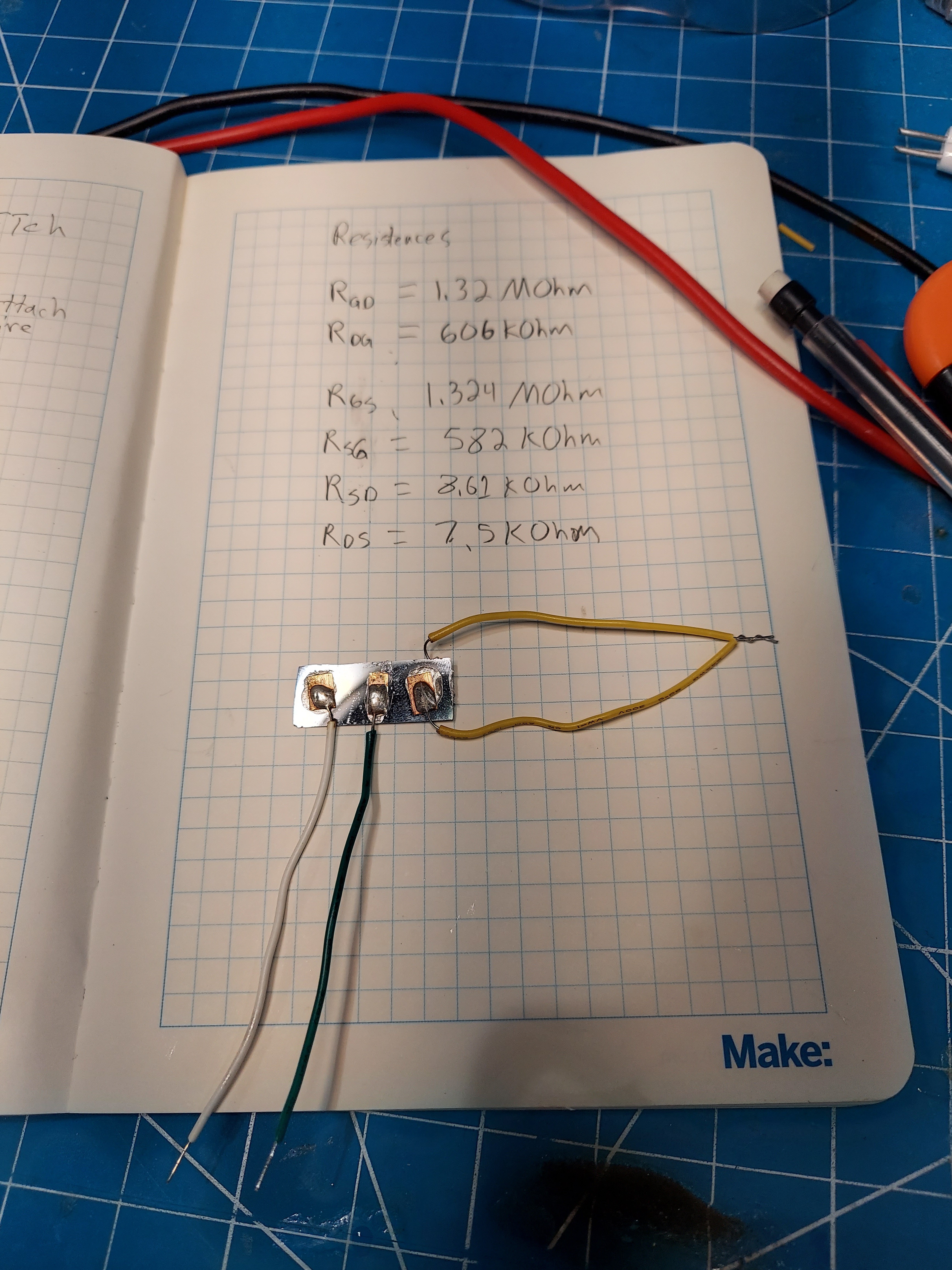
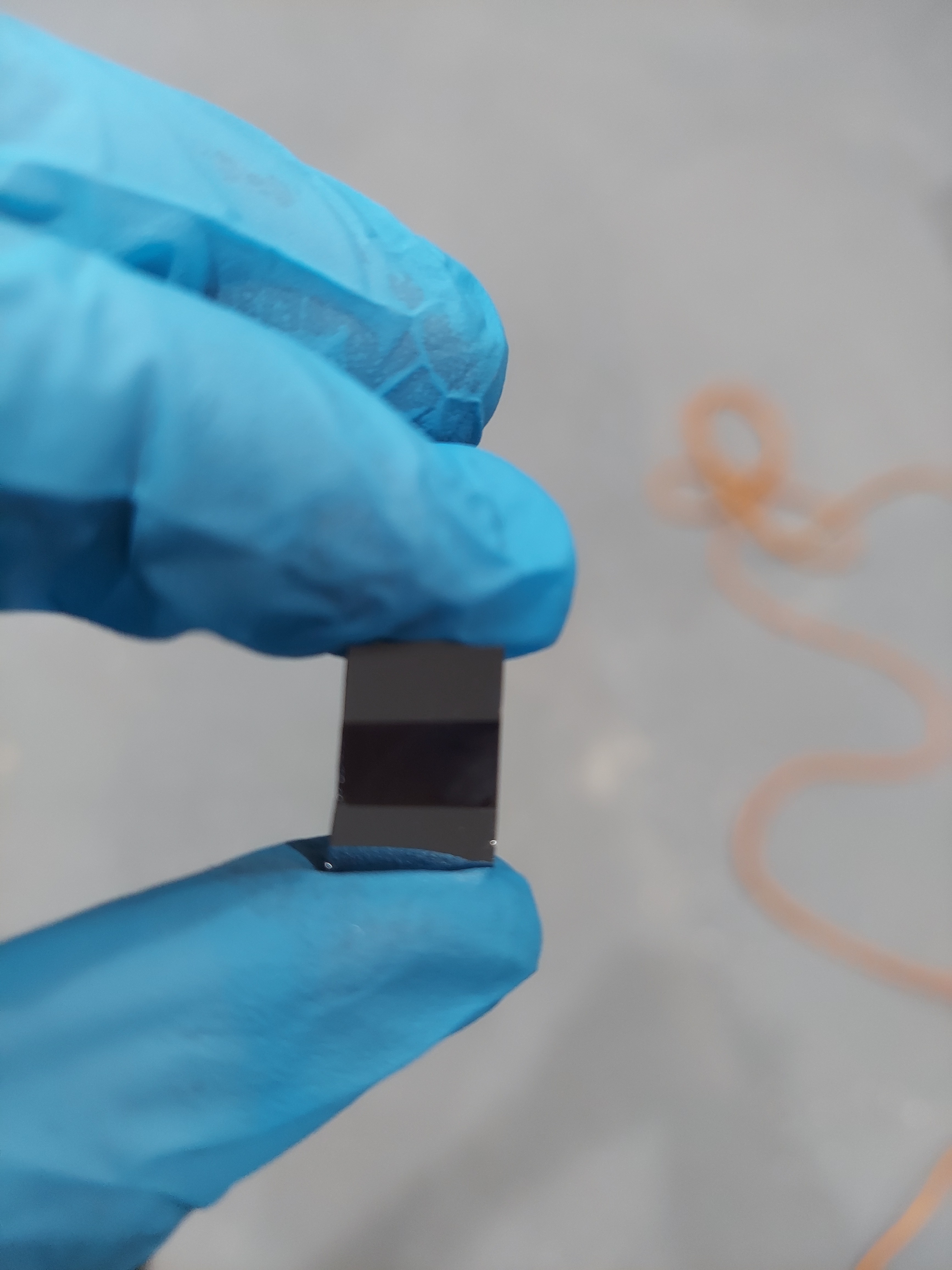
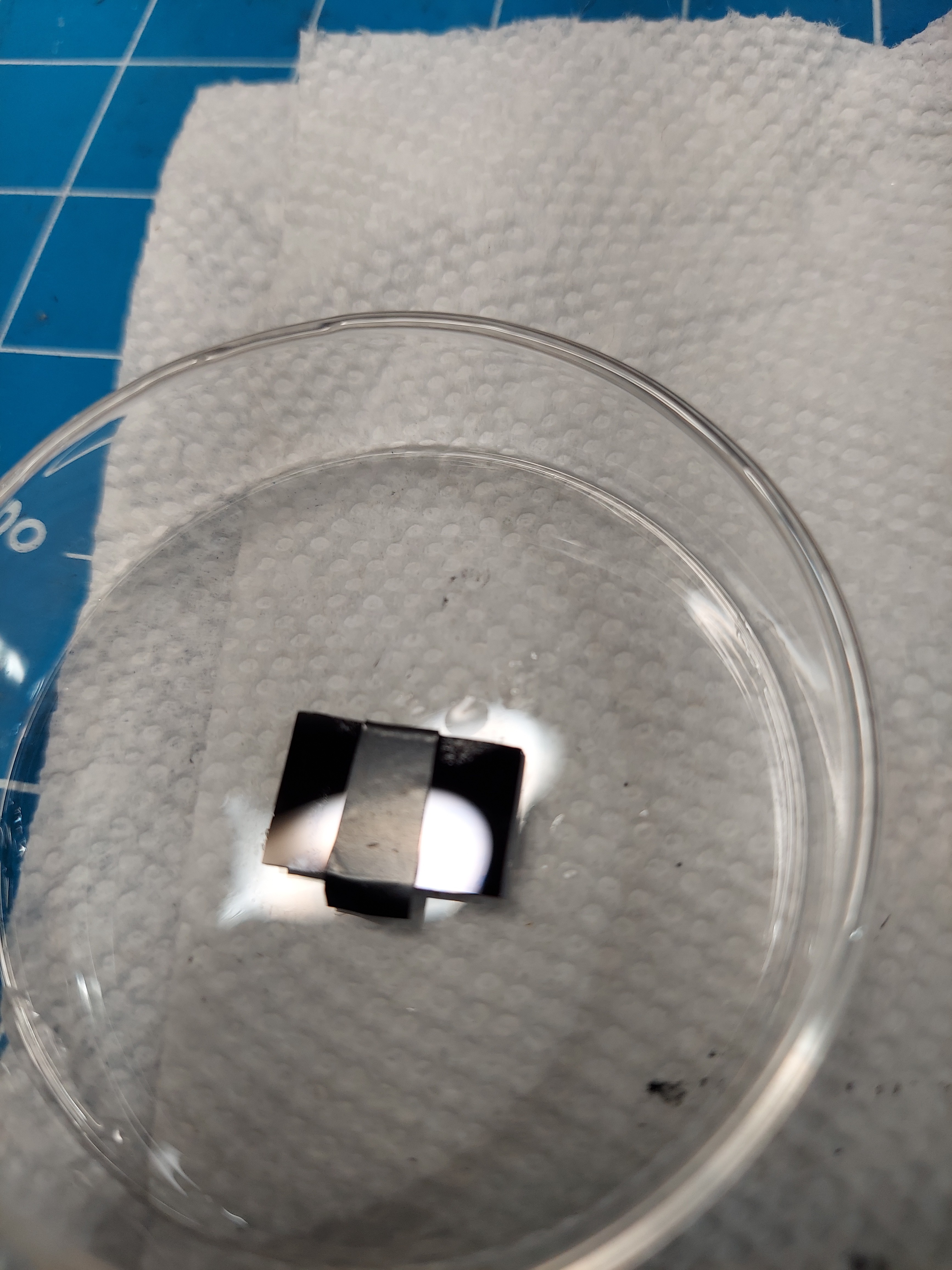
I decided to build a few simple PN junction devices - diodes. I also followed Sam Zeloof's recipe for a MOSFET - unfortunately - I'm fairly sure the gate shorted because the oxide was too thin.
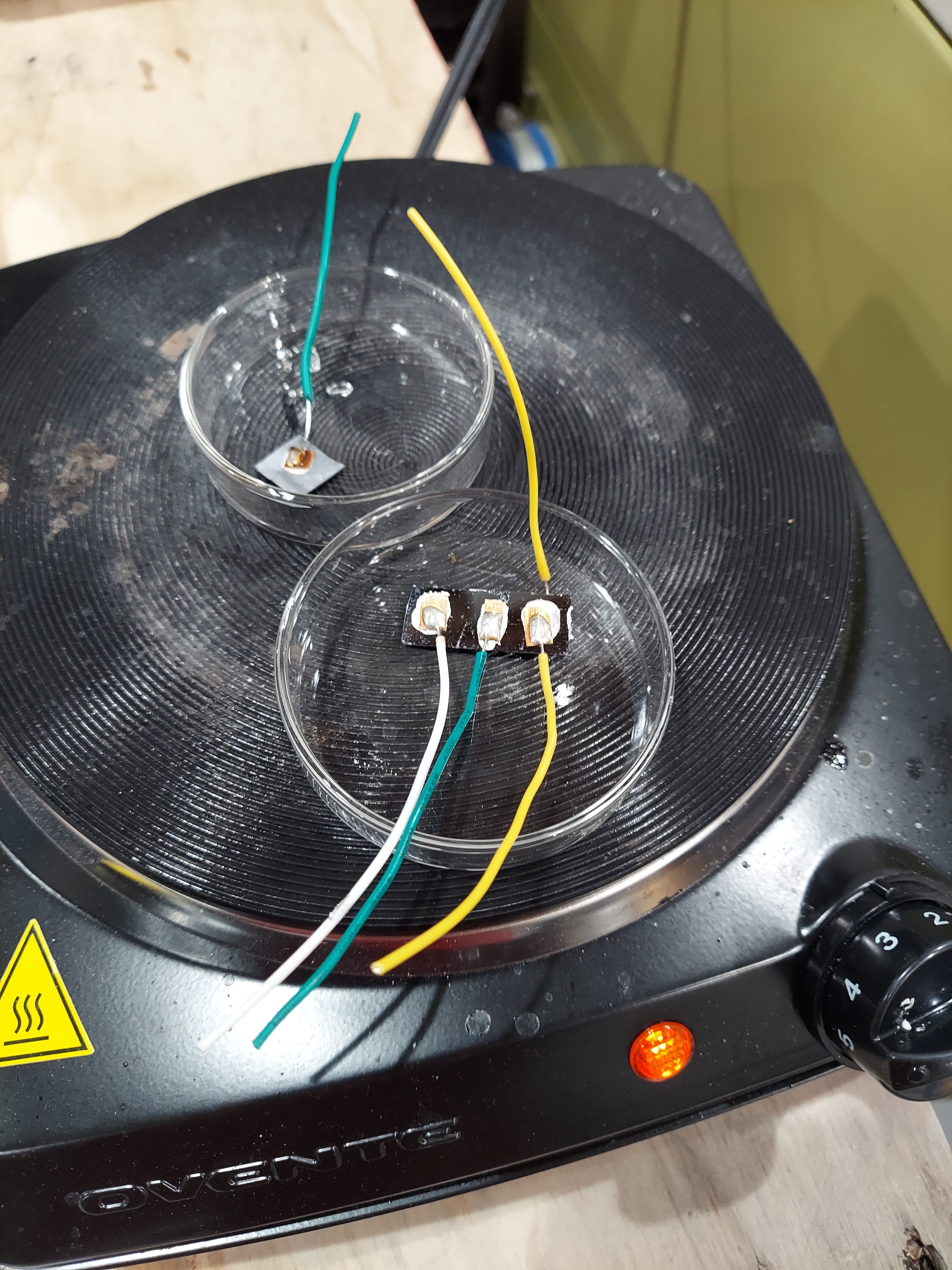
All the PN devices I built exhibited 'diode-like' properties - having a voltage drop higher in one direction, having a different resistance per direction. They also generated a small voltage under direct light.
I still need to buy or build a diode tester - aka 'octopus' device to generate V/I current traces.
It's been a steep learning curve the past week, and I think my devices are becoming more refined and successful.
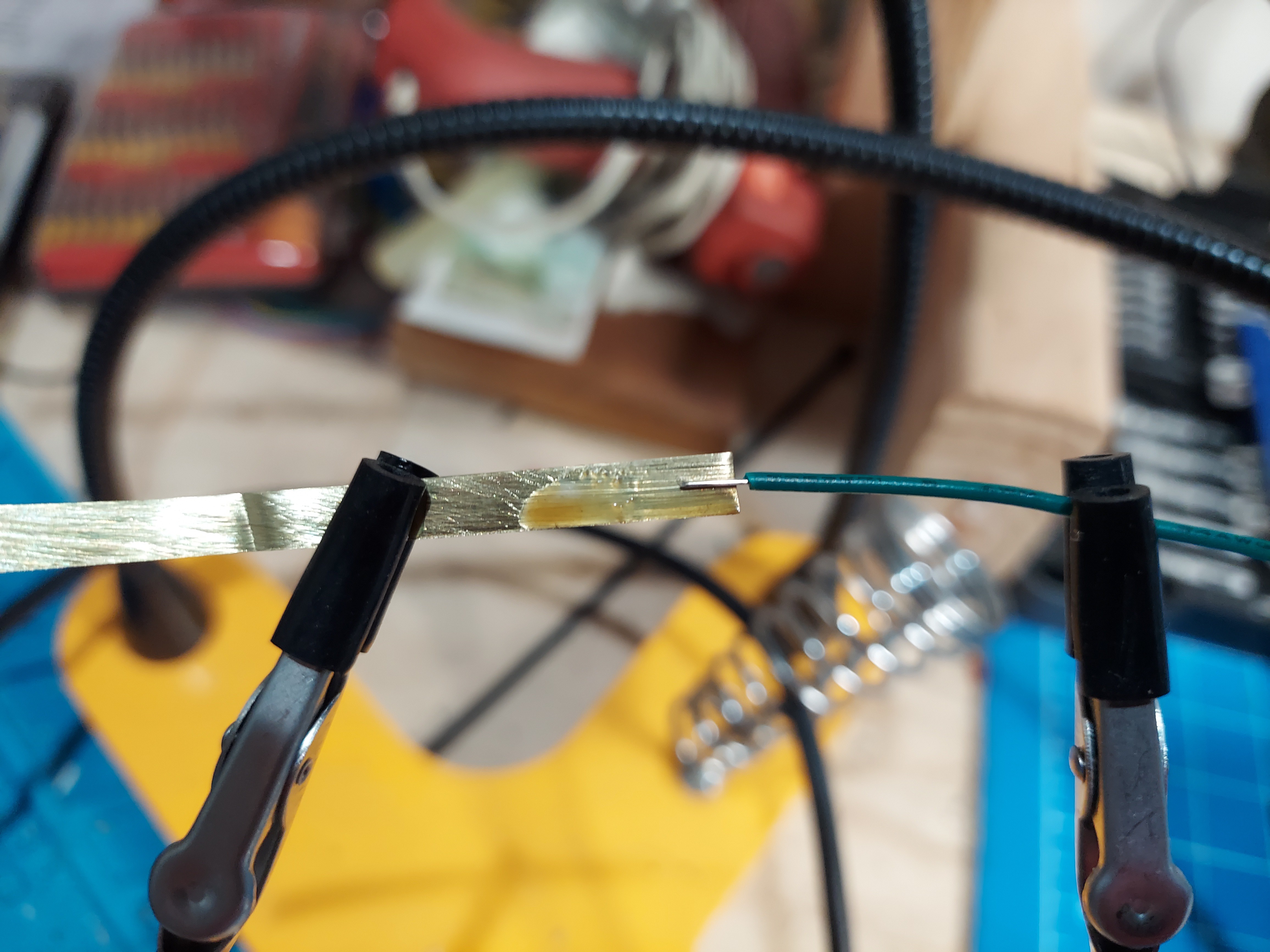
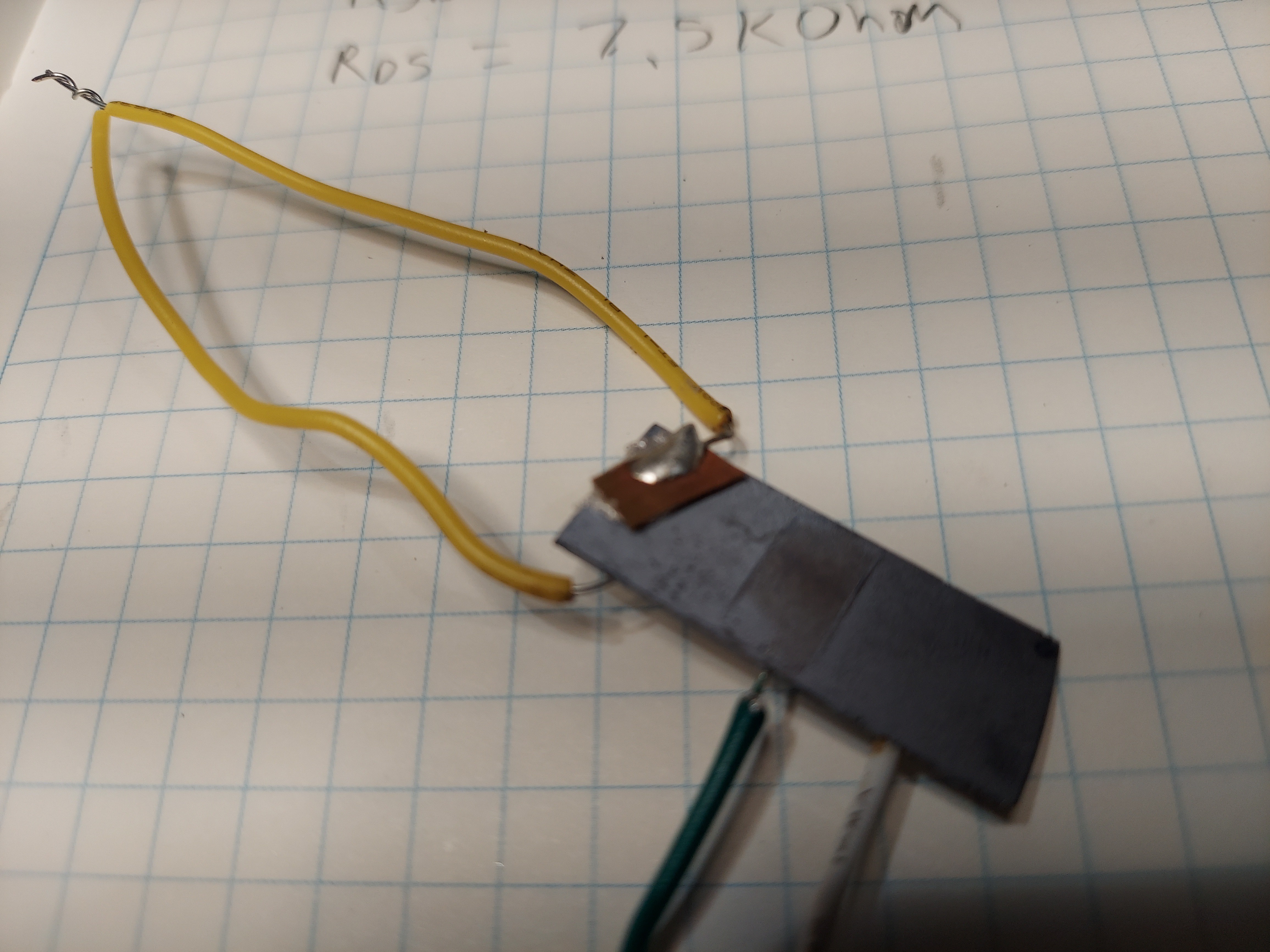
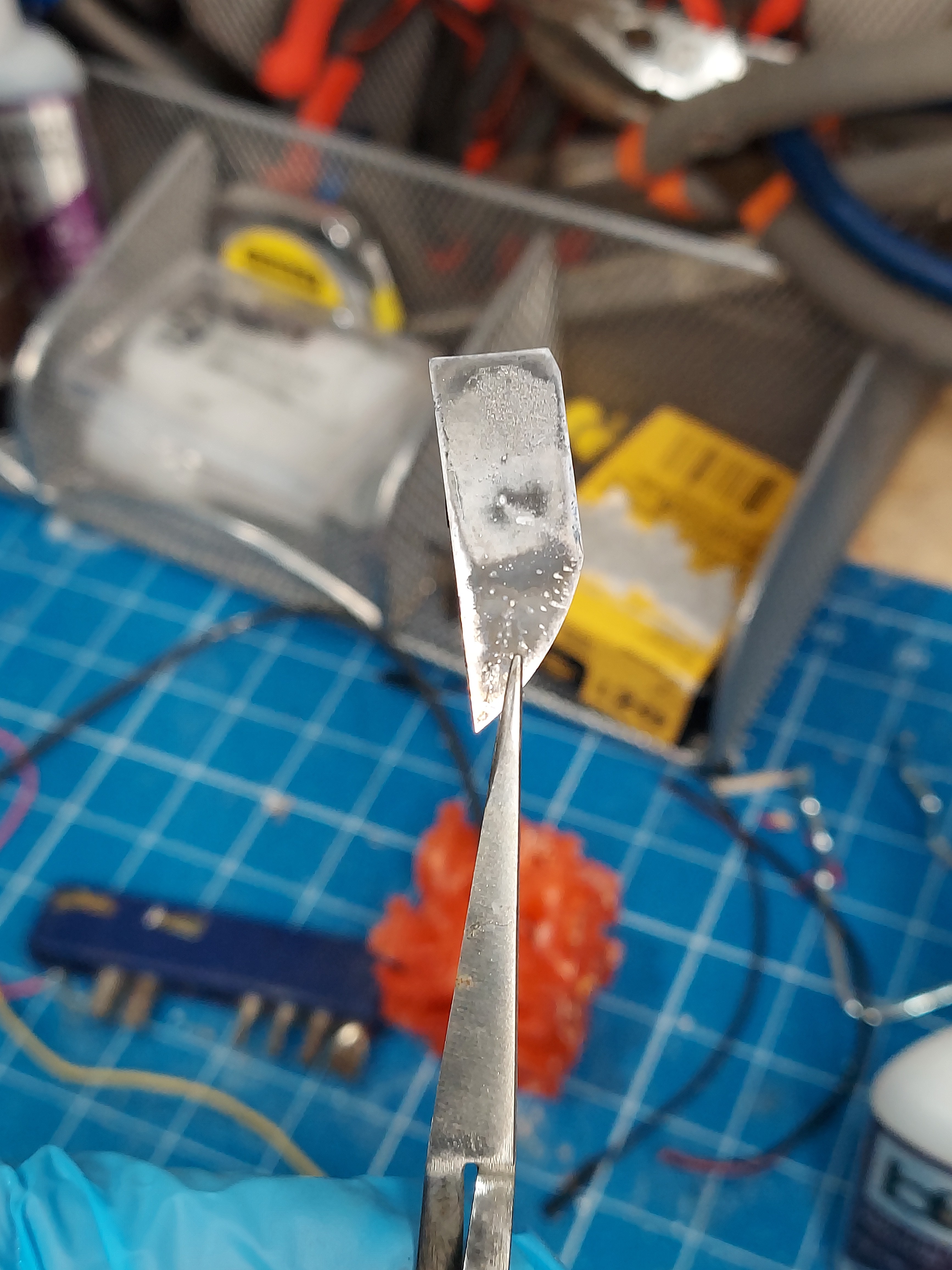
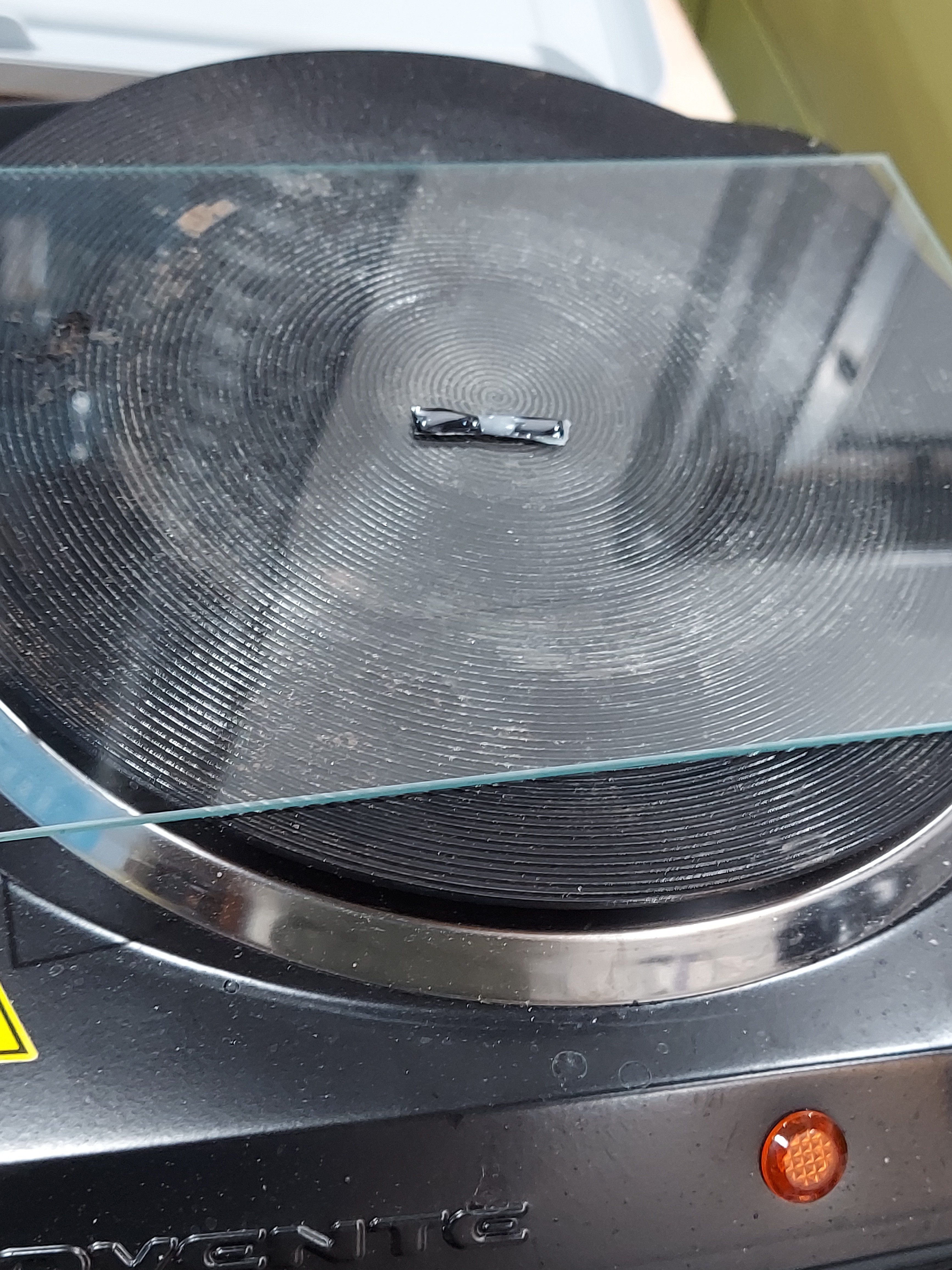
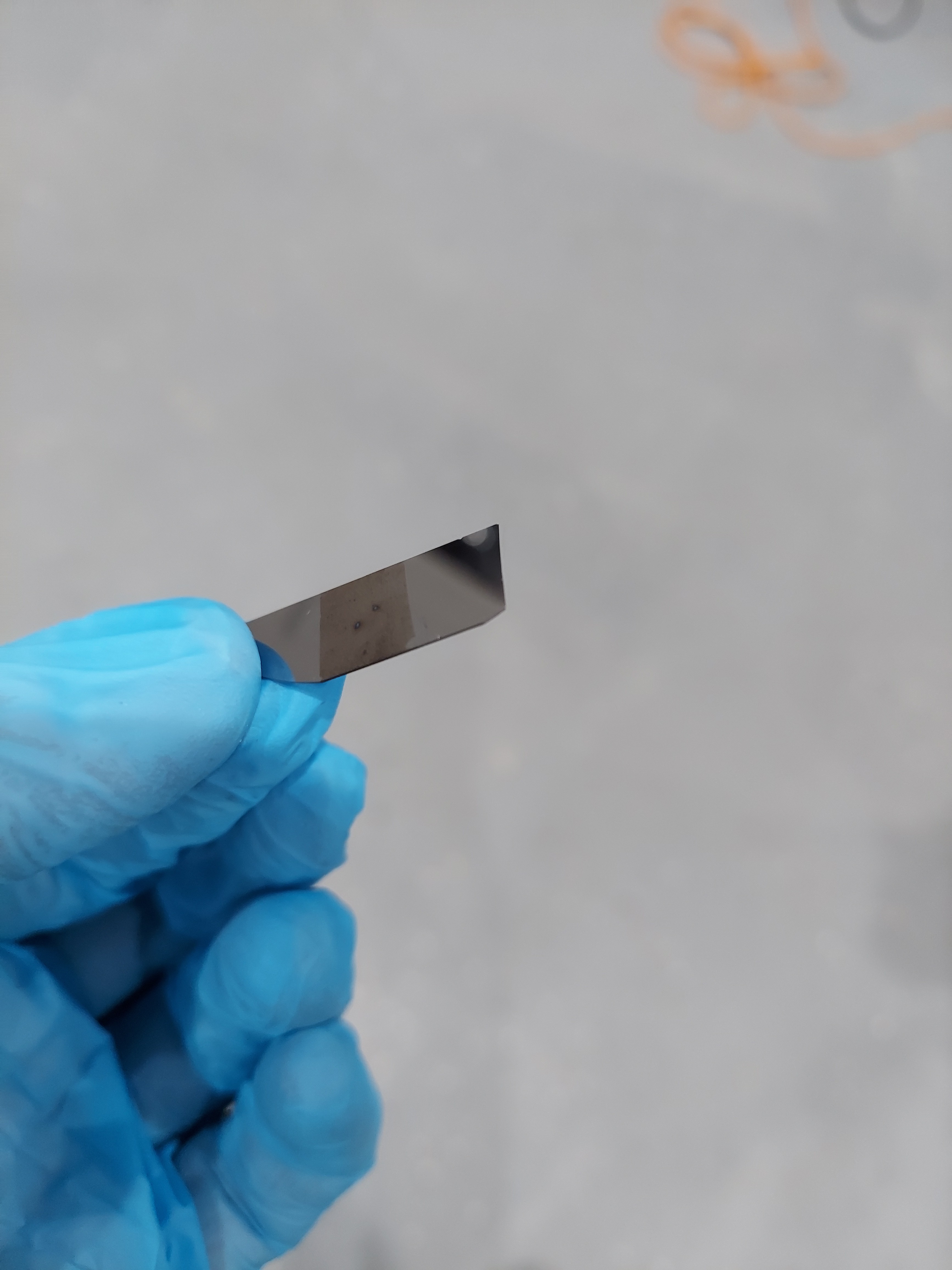
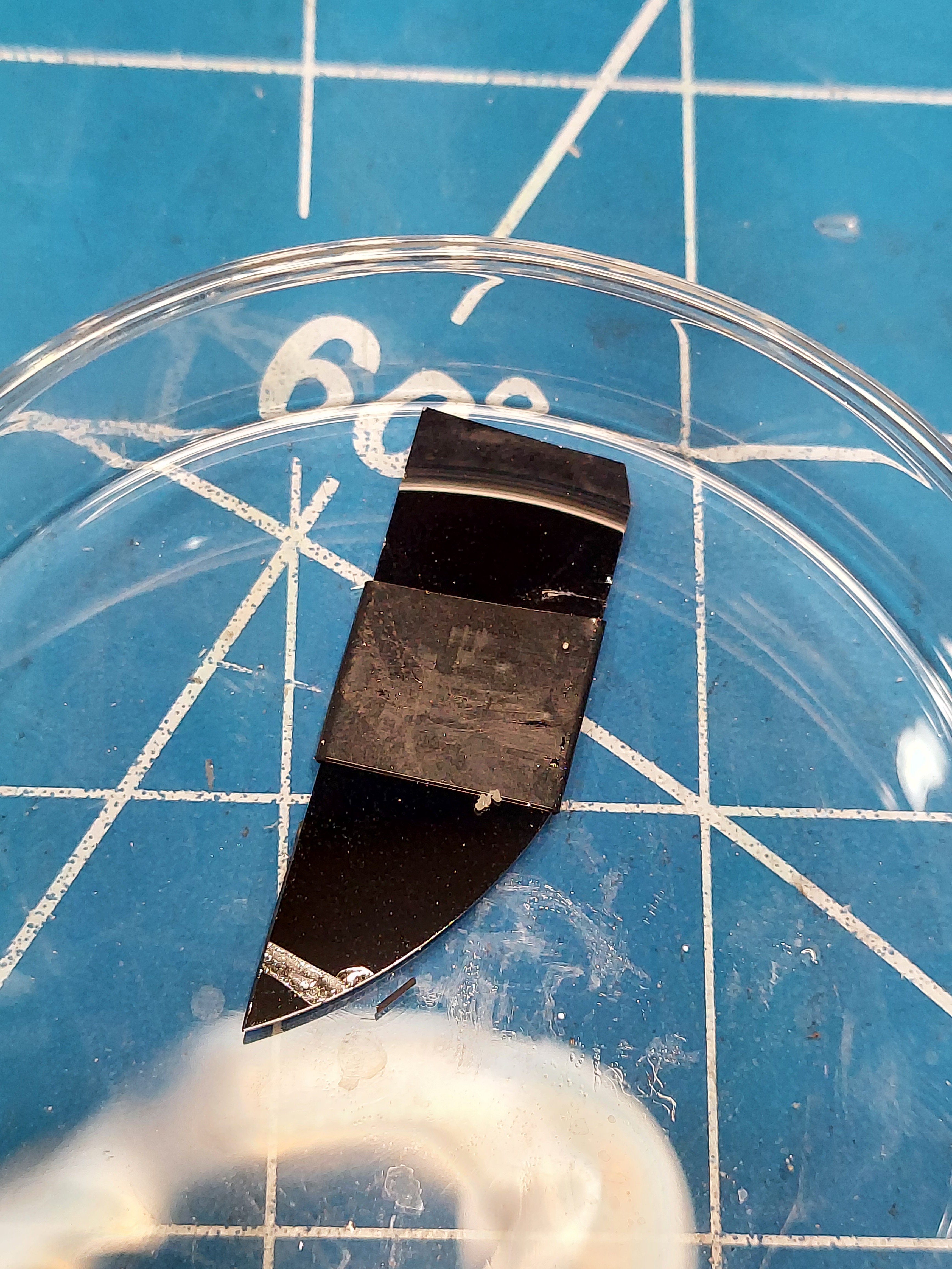
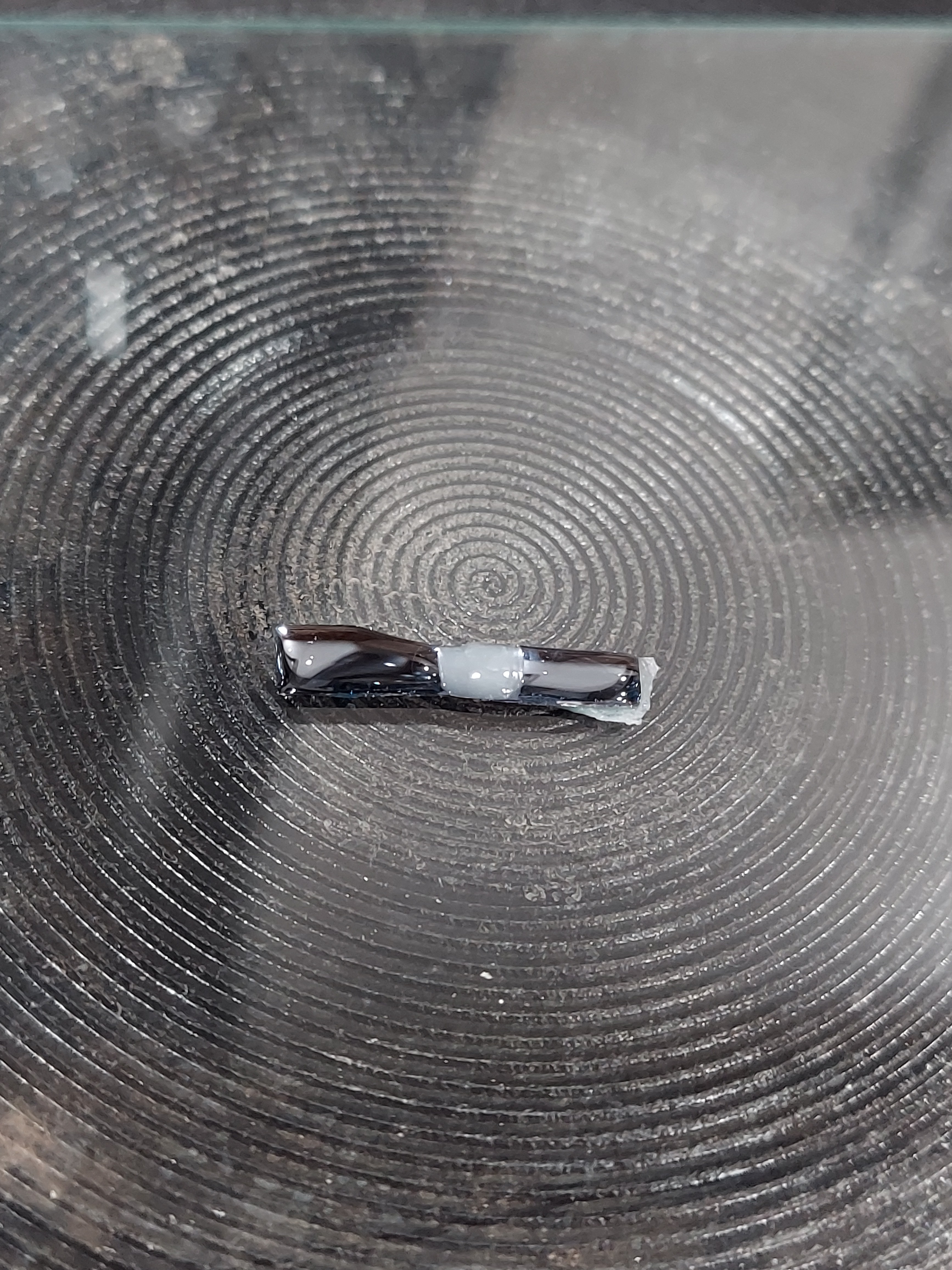
I'm making attachments to the silicon with small strips of sheet brass bonded with a silver epoxy. It's a heat-curing epoxy, not a 2-part epoxy, so it was more practical to have a footpad.
![]()
![]()
![]()
![]()
![]()
-
Coil rebuild
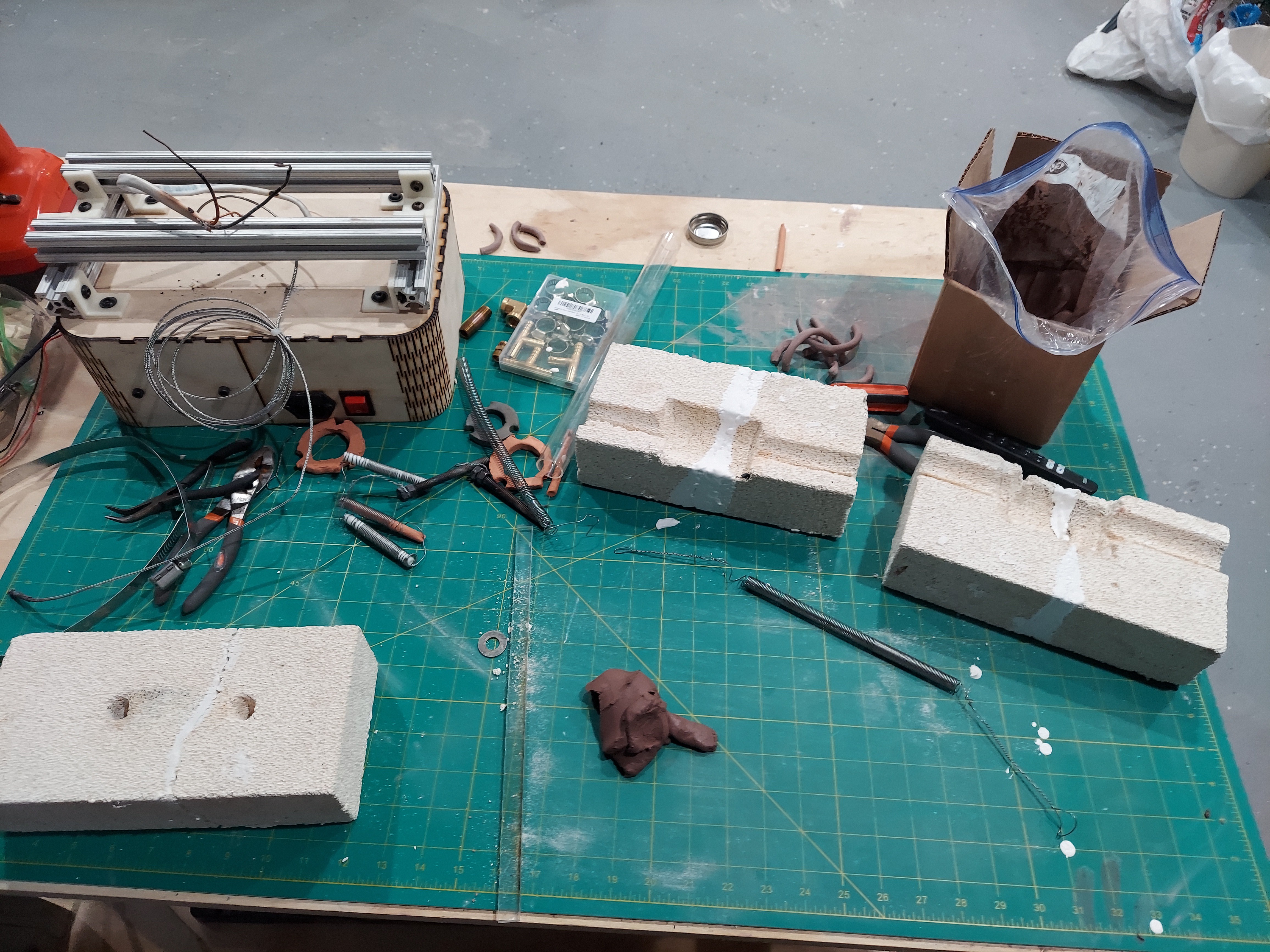
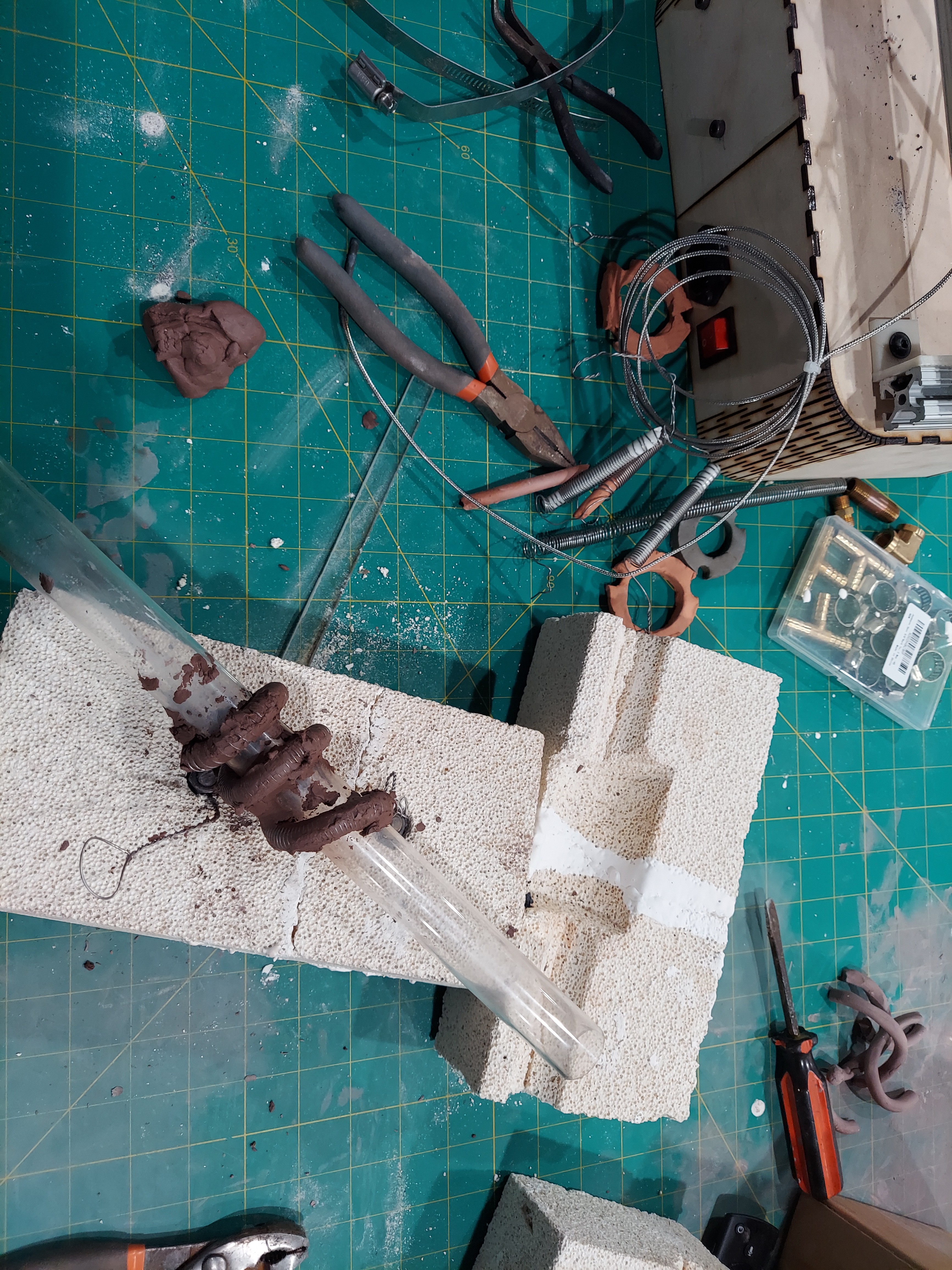
07/03/2022 at 23:10 • 0 commentsSo, after running the tube forge for a while, I had a problem. Basically, the heating coils got too hot and started to melt/droop around the quartz tube. The coil ended up pooling at a the bottom of the forge, shorting, and burning out. I ended up fixing this by re-building the coil and this time - stuffing it full of clay! The idea is that the clay will bake in-place and form a hard ceramic that will act as a support for the coils - keeping them in place.
![]()
![]()
![]()
![]()
-
Experimenting with Silicon
06/21/2022 at 04:11 • 0 commentsNow that my semiconductor forge is (mostly) built, it's time to start actually building some PN junctions!
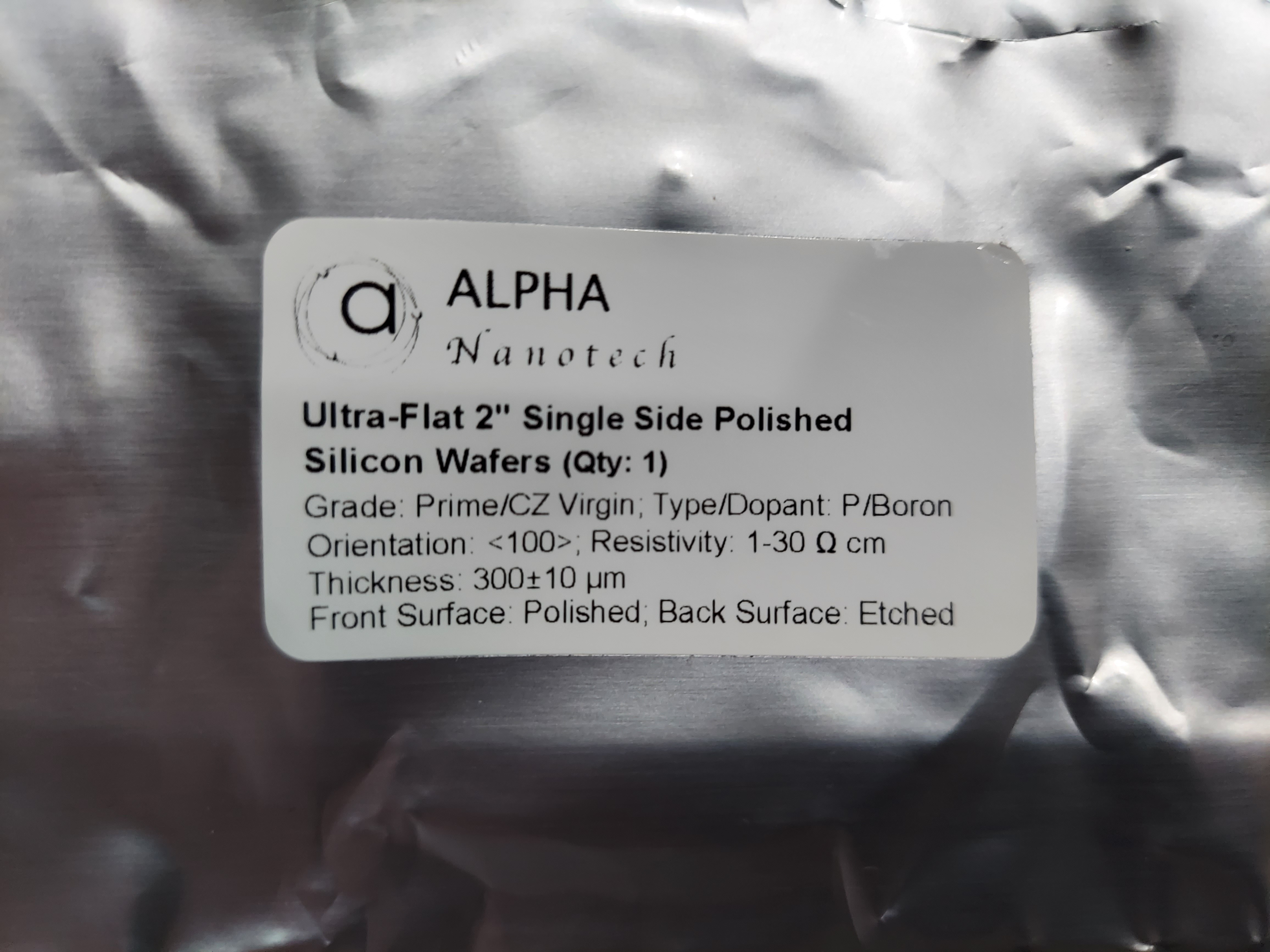
There are several things I'm going to have to do correctly in order to get this right. I've been experimenting with a P-Type wafer for a few days now.
Here's some initial notes:
- Breaking the silicon is more tricky than it looks. My first 2" wafer shattered leaving only a few sizeable working pieces.
- Growing oxide layers - I downloaded and printed the silicon dioxide growth rate chart (https://cleanroom.byu.edu/oxidetimecalc) and used the calculator to estimate growing oxide layers of different thicknesses. My furnace can blow water mist over the chips for increased oxide growth.
- Working with Chemicals!
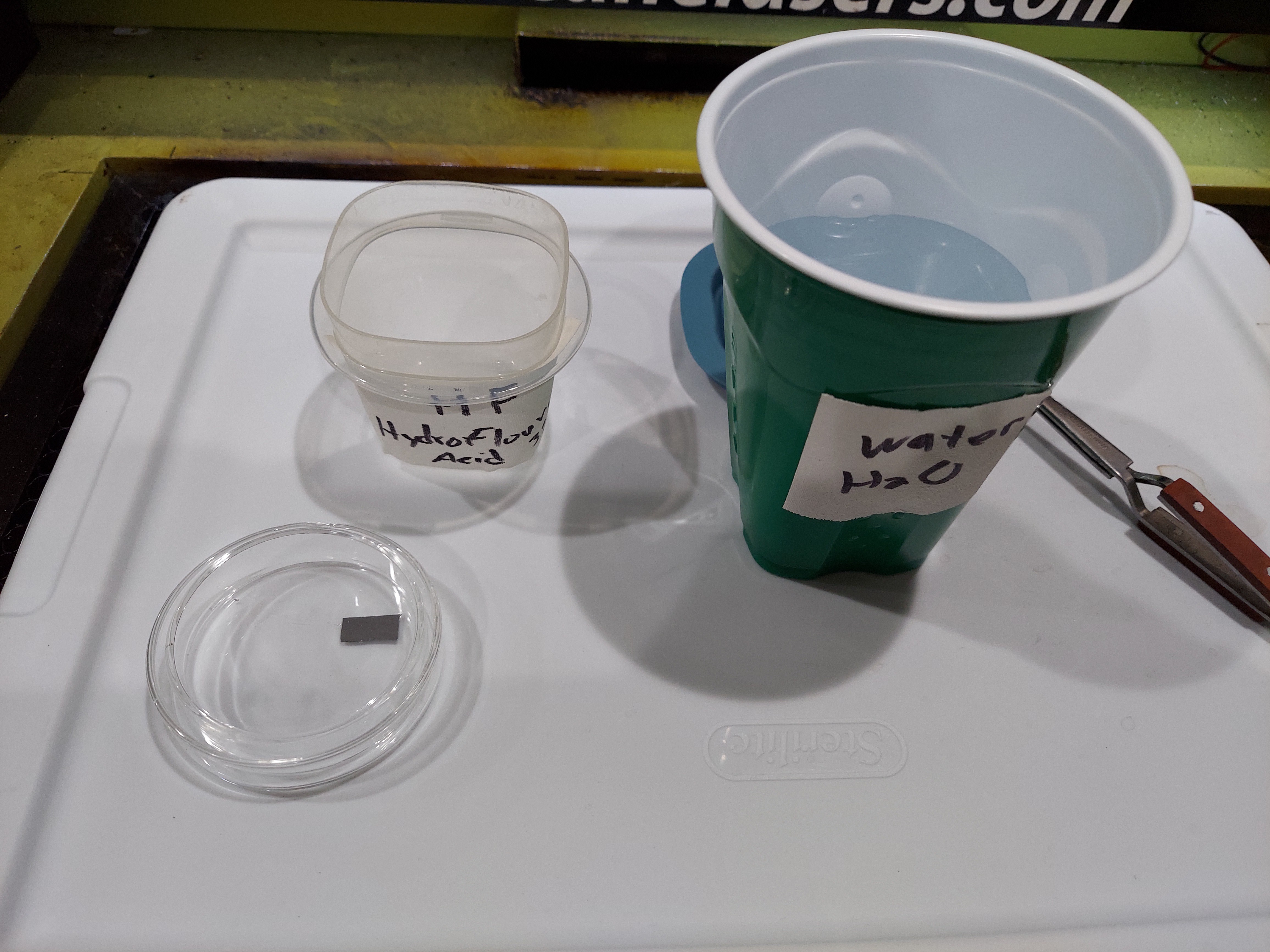
- Hydrofluoric acid is some pretty nasty stuff.
- You need to wear safety gear when using chemicals.
- You need a ventilation system - luckily I thought of that when I built my lab.
- You're going to need to collect few essential chemicals to make this all work
- Etching Silicon dioxide layers!
- Masking systems
- Photoresist (positive and negative)
- SLA UV resins can be used along with UV DLP and UV laser systems. I'm starting to experiment with these and getting some positive results.
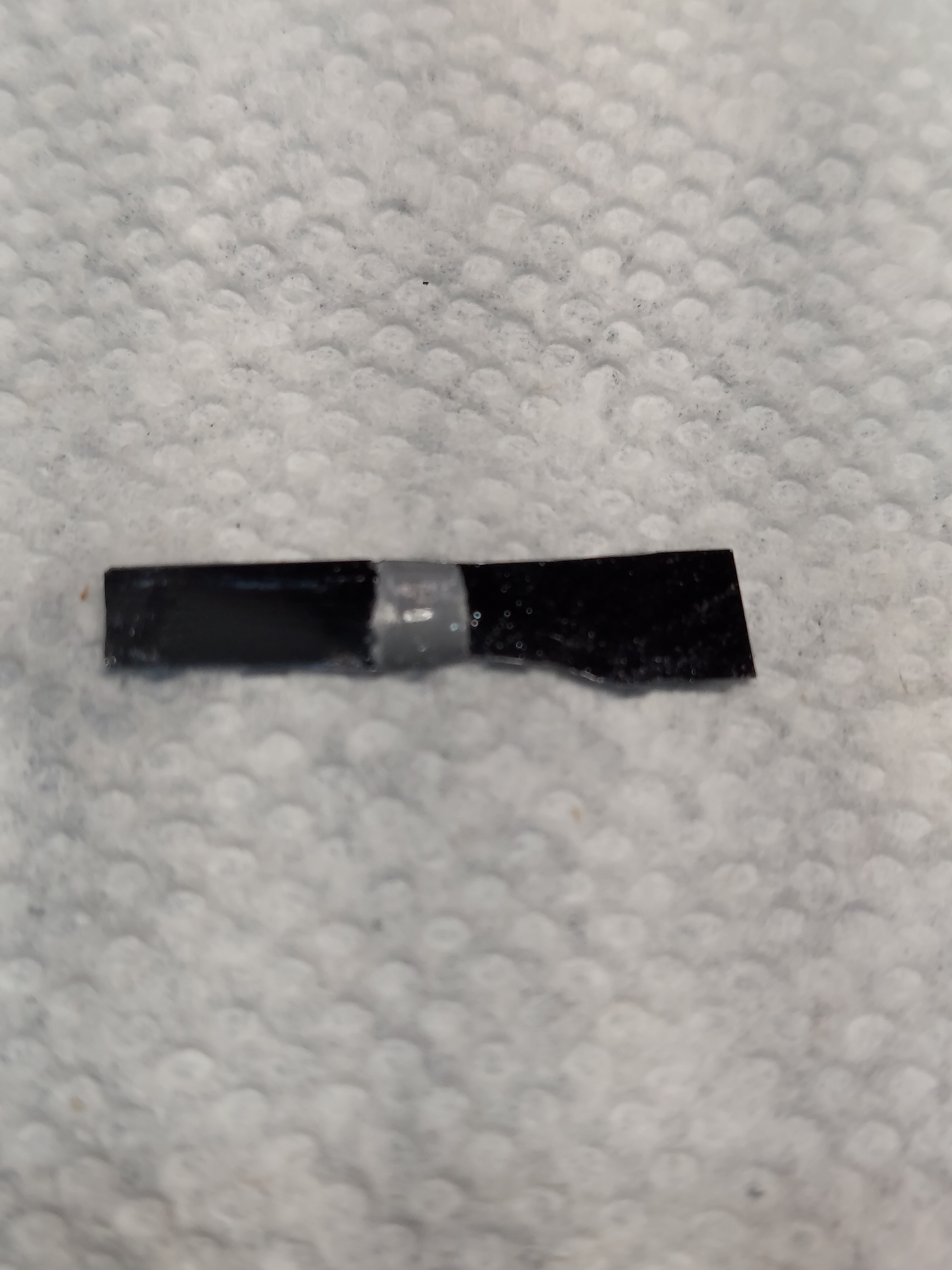
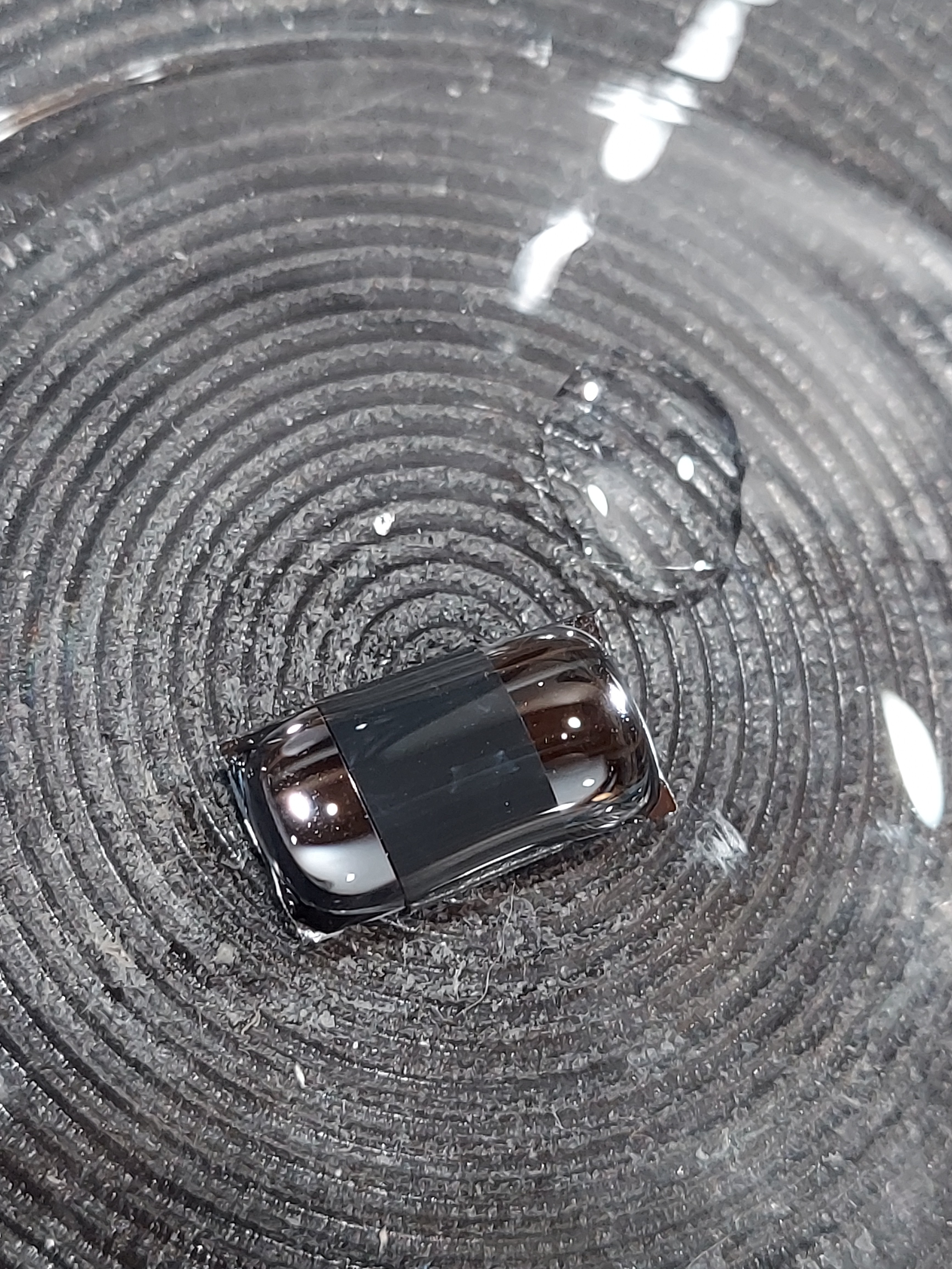
- Black electrical tape cut with a razor (What I'm starting with)
- Masking systems
- HF acid is used to etch the silicon dioxide layers
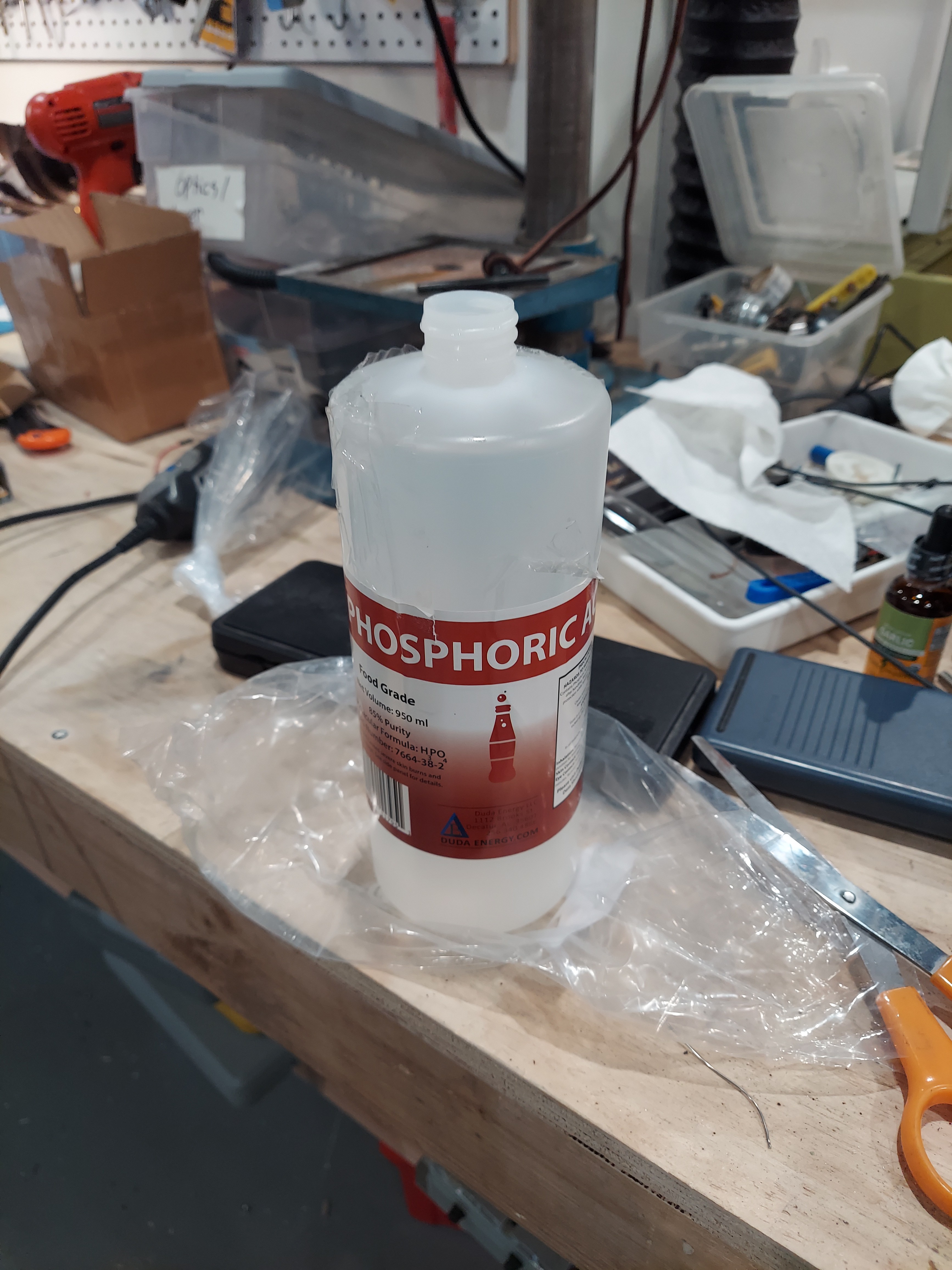
- Using dopants! So - I bought a bottle of 85% Phosphoric acid to use ad an N-Type dopant. I also bought boric acid powder. Neither were hard to find or too expensive.
- So far - I have simply put a few drops of phosphoric acid on a pieces of silicon and baked it in for an hour at 1000c. Results have been very promising!
- Measuring and testing
- I'm a big believer in documenting and recording results.
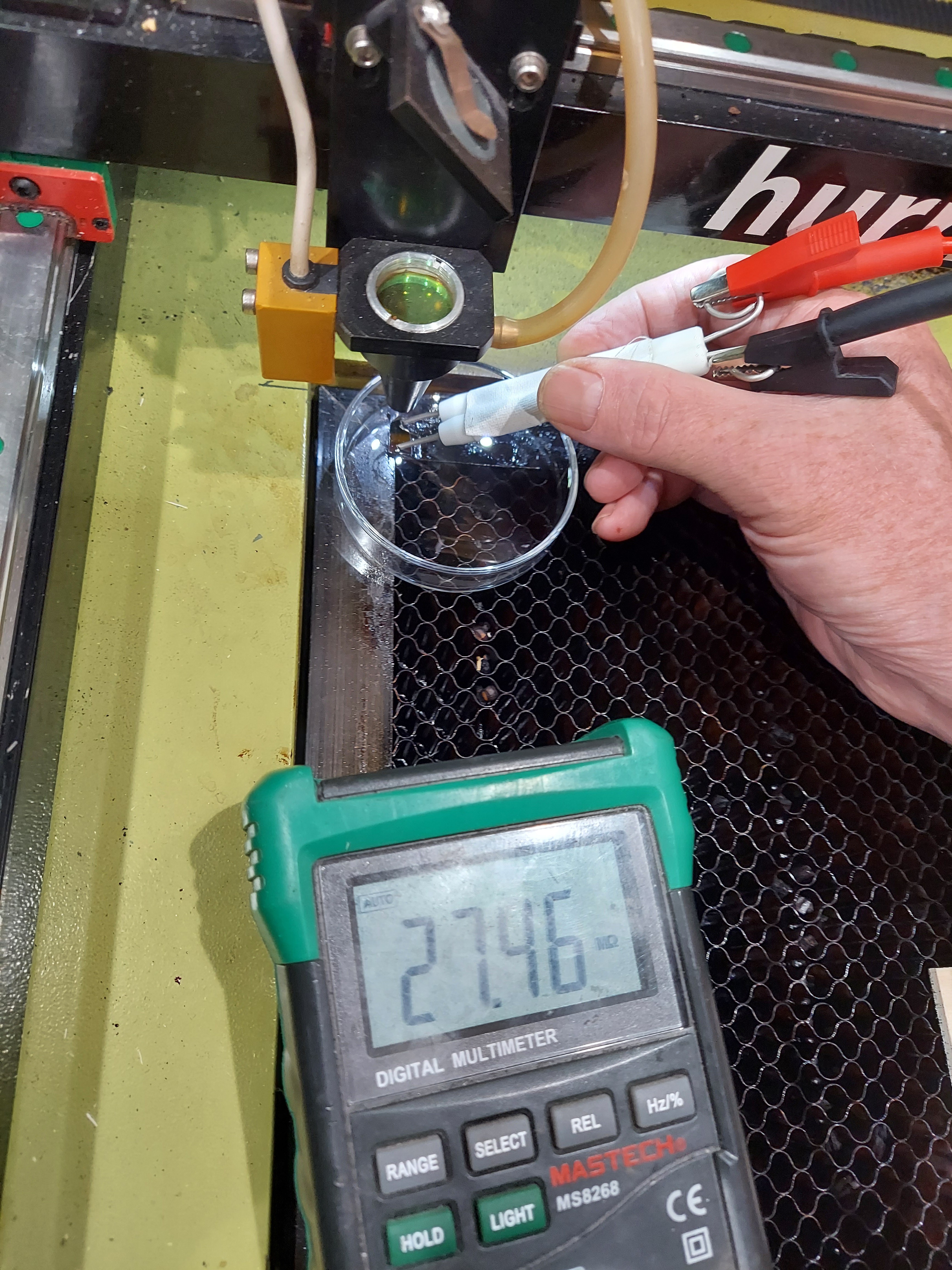
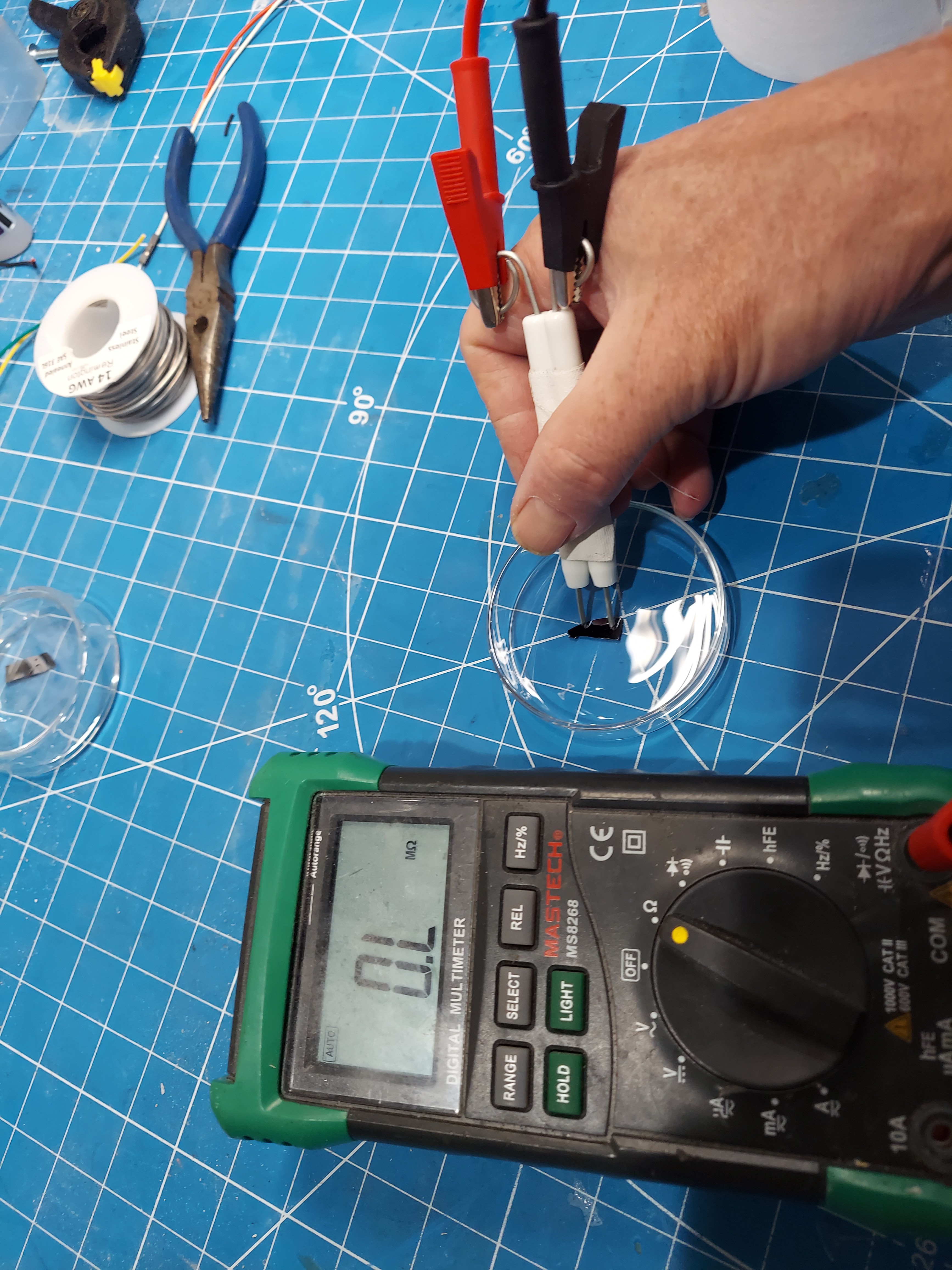
- I measured the resistance of the P-type wafer using a makeshift 1-cm probe after I received it. Oxide layers had already formed, so the results were difficult to determine - somewhere in the megaohms range.
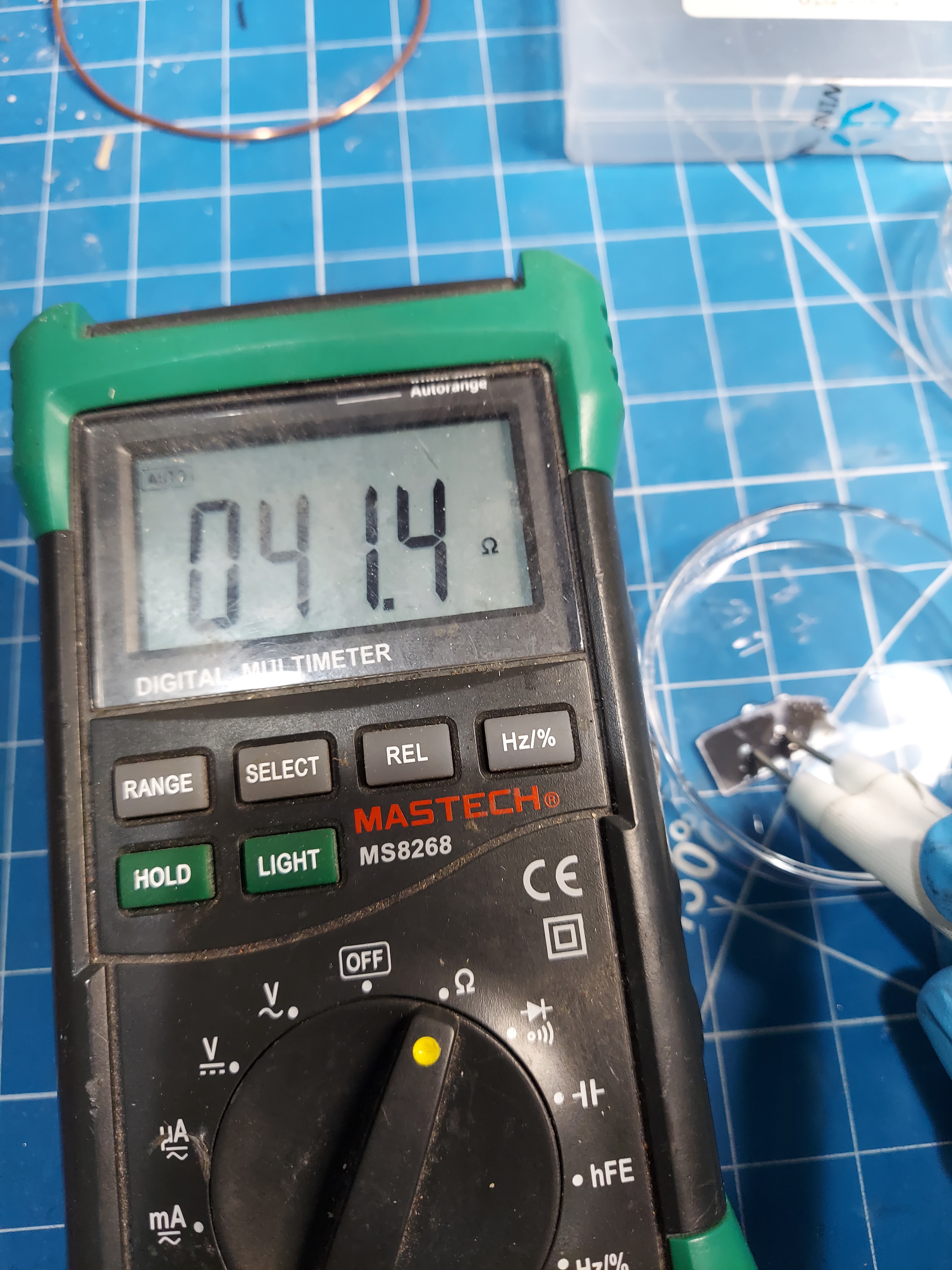
- After a quick dip in some HF, the silicon was reading around ~300 KOhms/cm for the P-Wafer material.
- After doping the material with phosphorus, drying, and baking for 145 mins at 1000c, the material was retrieved, dipped in HF to remove the oxide layer, and retested. The material was now in the 30 -60 Ohm range per cm.
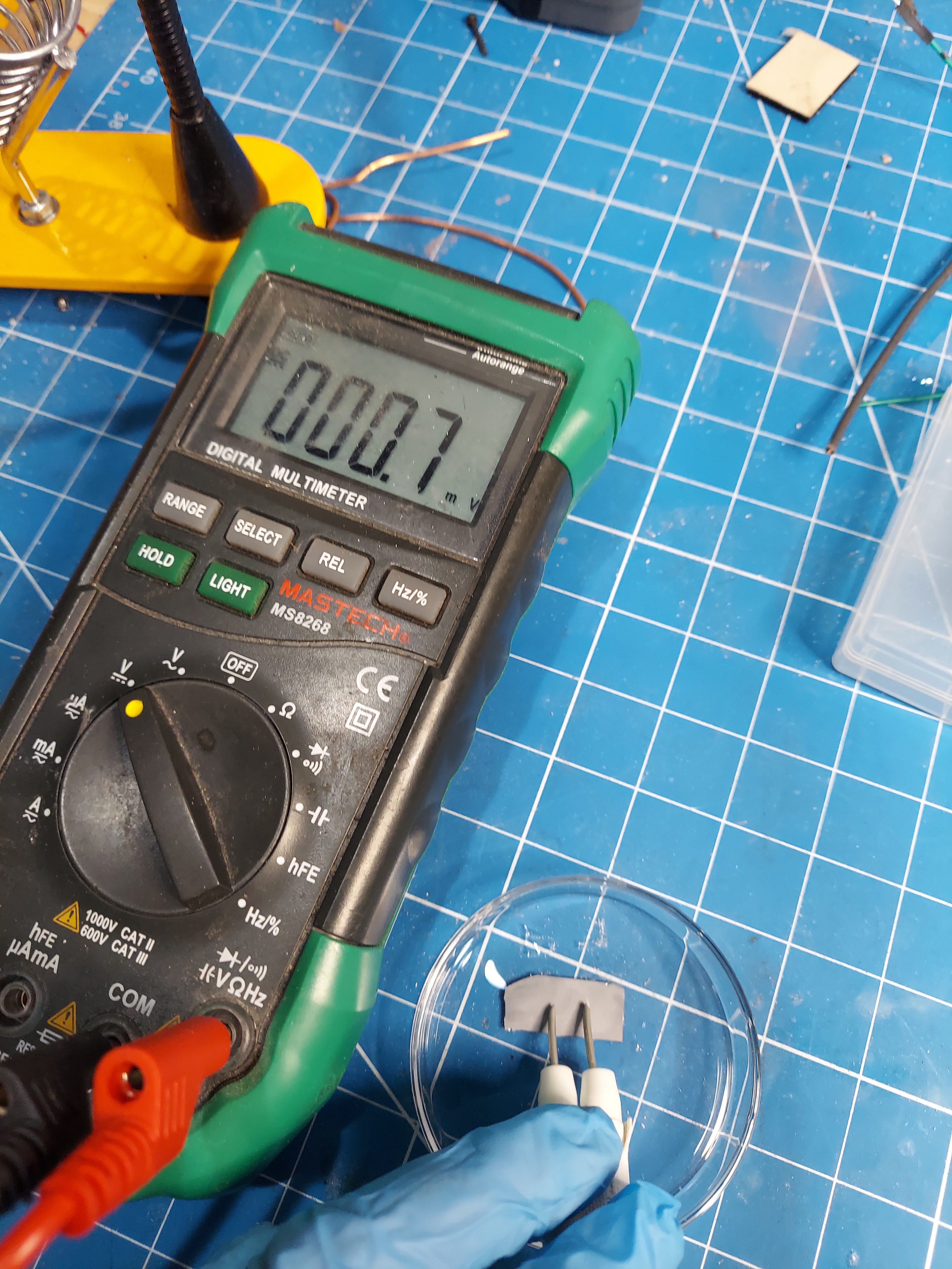
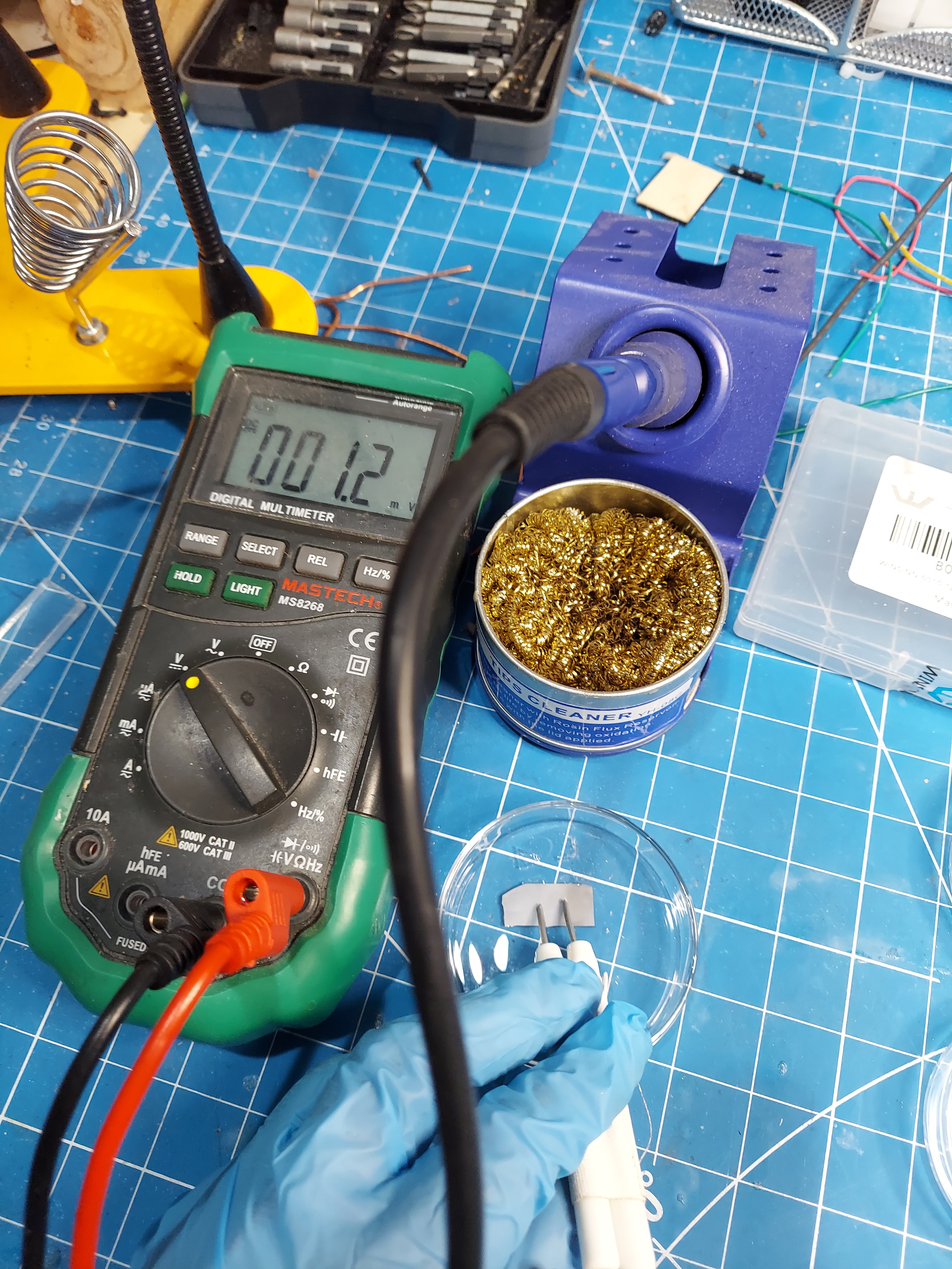
- The hot probe test on the positive anode also show the characteristic rise in voltage as heat was applied.
- This is a pretty good indicator that I was able to successfully dope regions of my p-type silicon with phosphorus, making it into an n-type material.
- I'm going to need a V/I curve tracer in order to better see how these semiconductors are behaving.
![]()
![]()
![]()
![]()
![]()
![]()
![]()
![]()
![]()
![]()
![]()
![]()
![]()
![]()
![]()
![]()
![]()
![]()
![]()
-
Putting it all together!
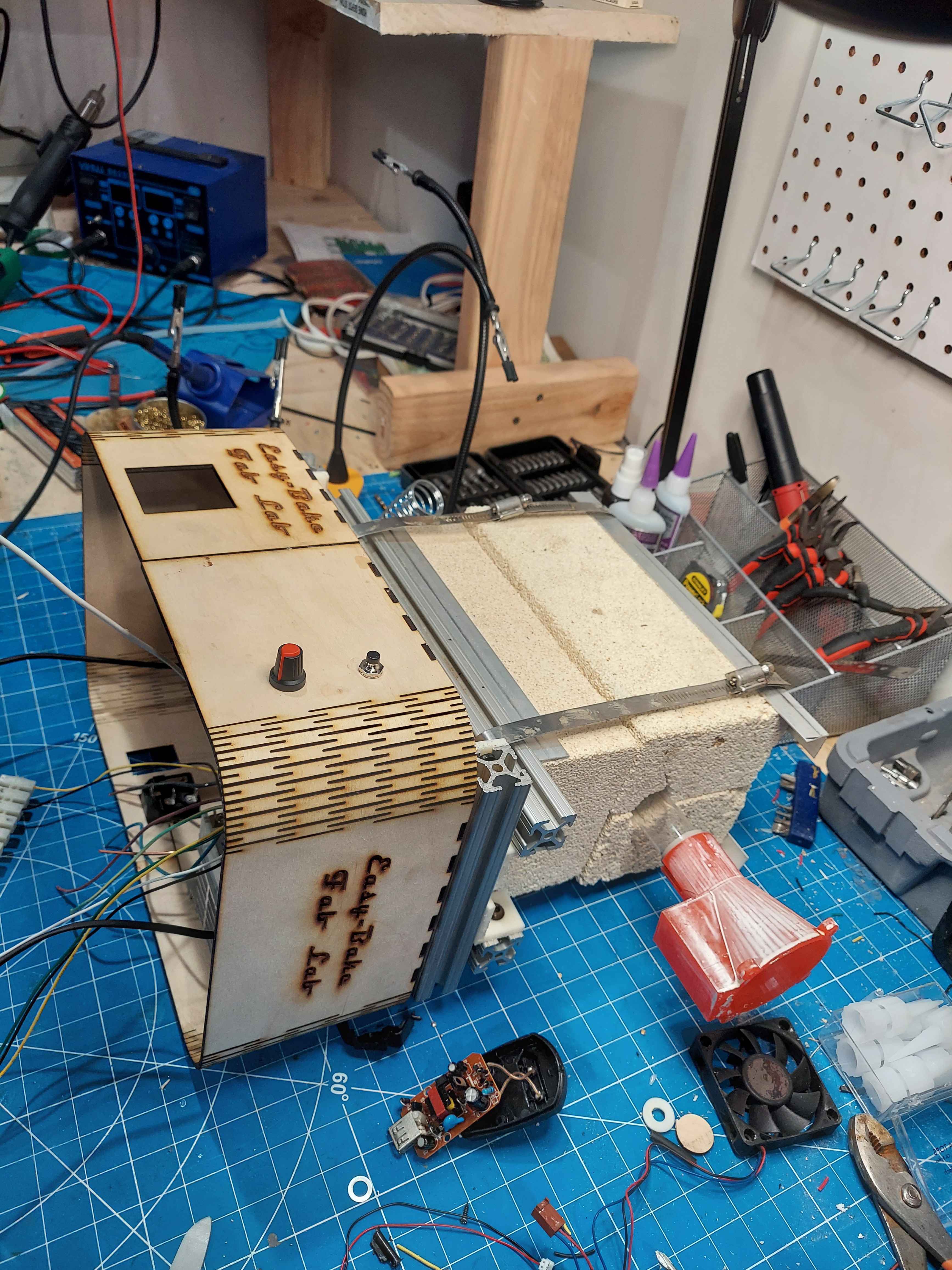
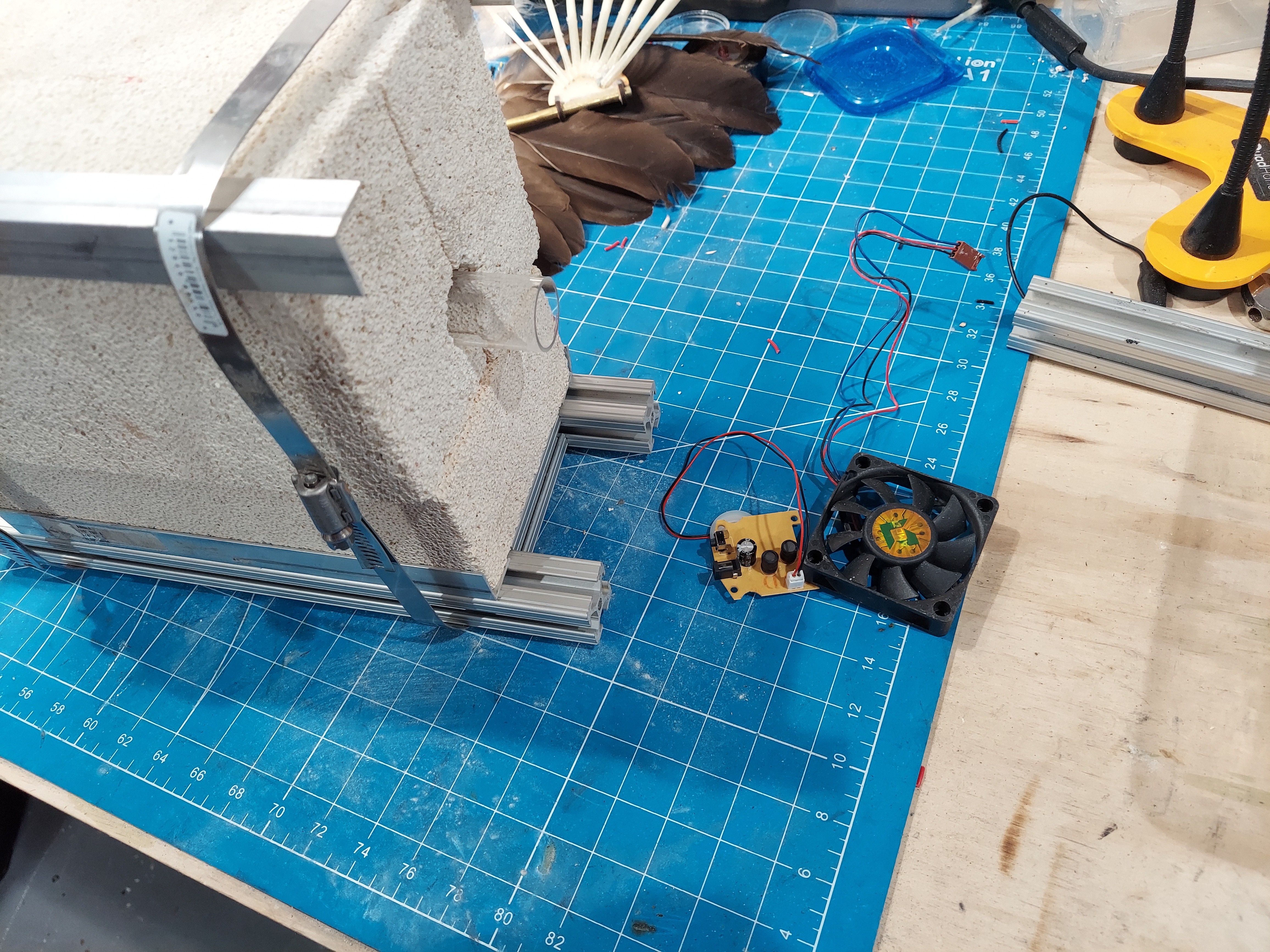
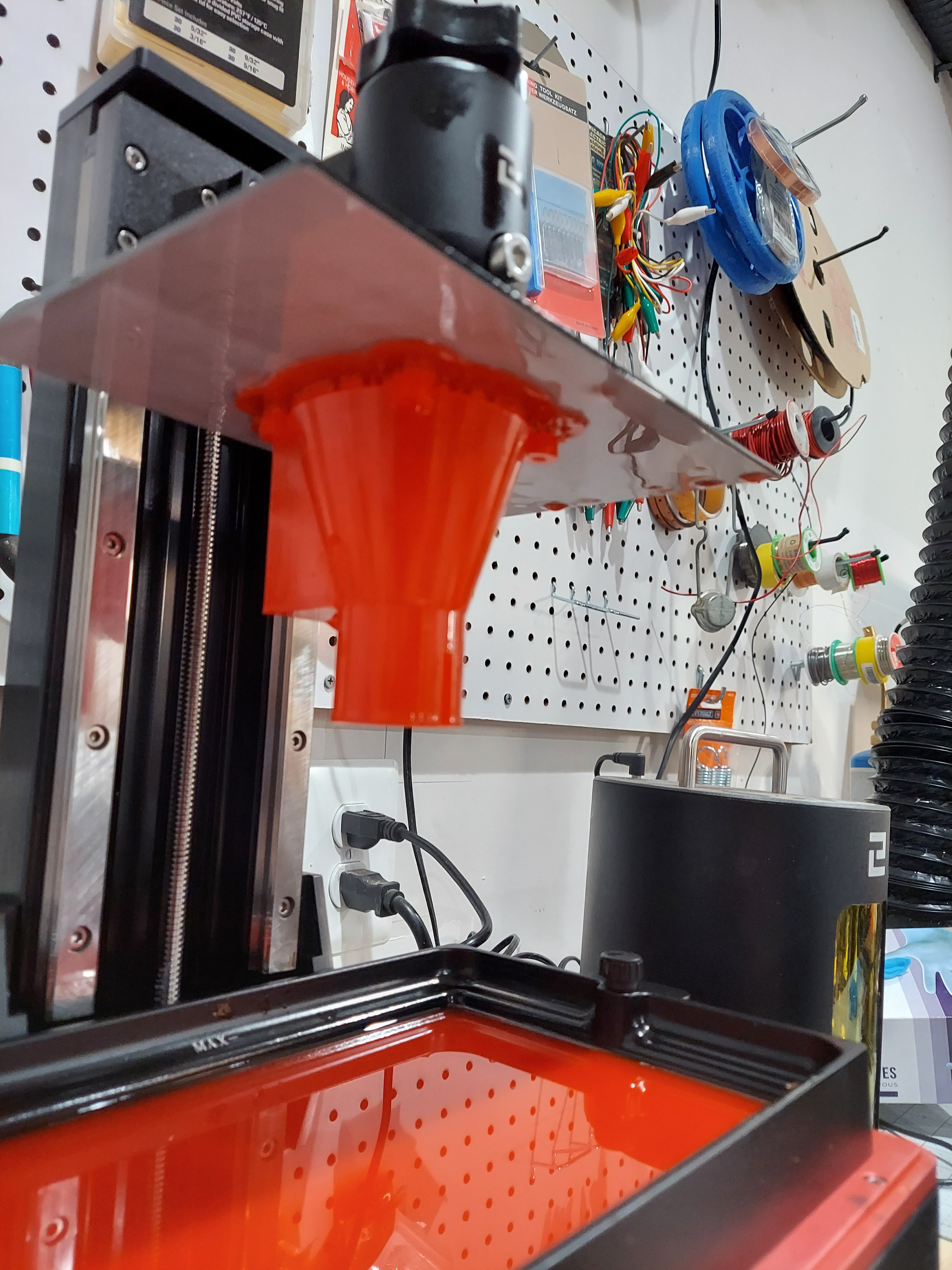
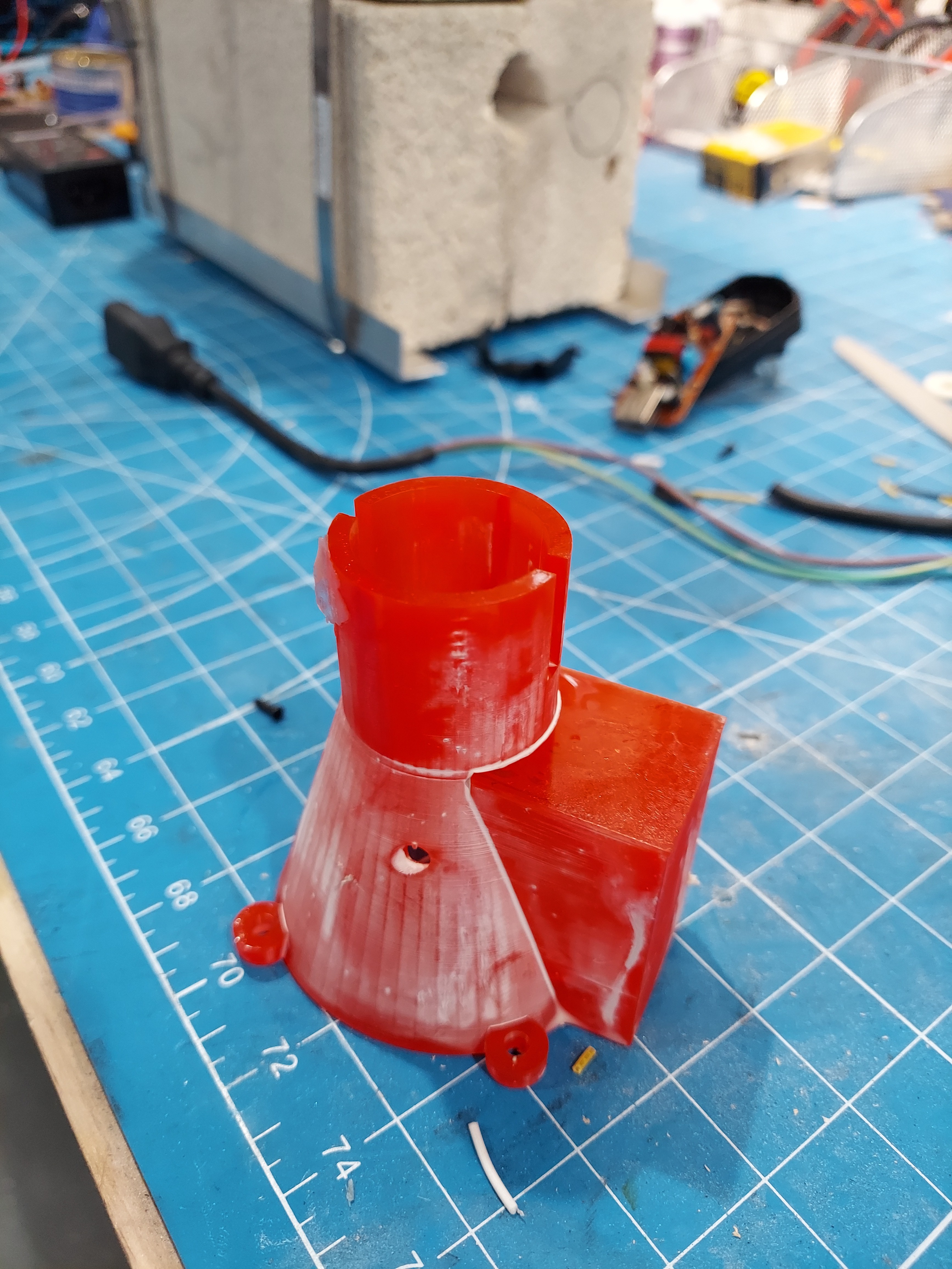
06/18/2022 at 21:44 • 0 commentsI 3d printer a fan cowl with an area for holding liquids. This is used with an ultrasonic atomizer to vaporize water or other liquids to flow through the heater core.
![]()
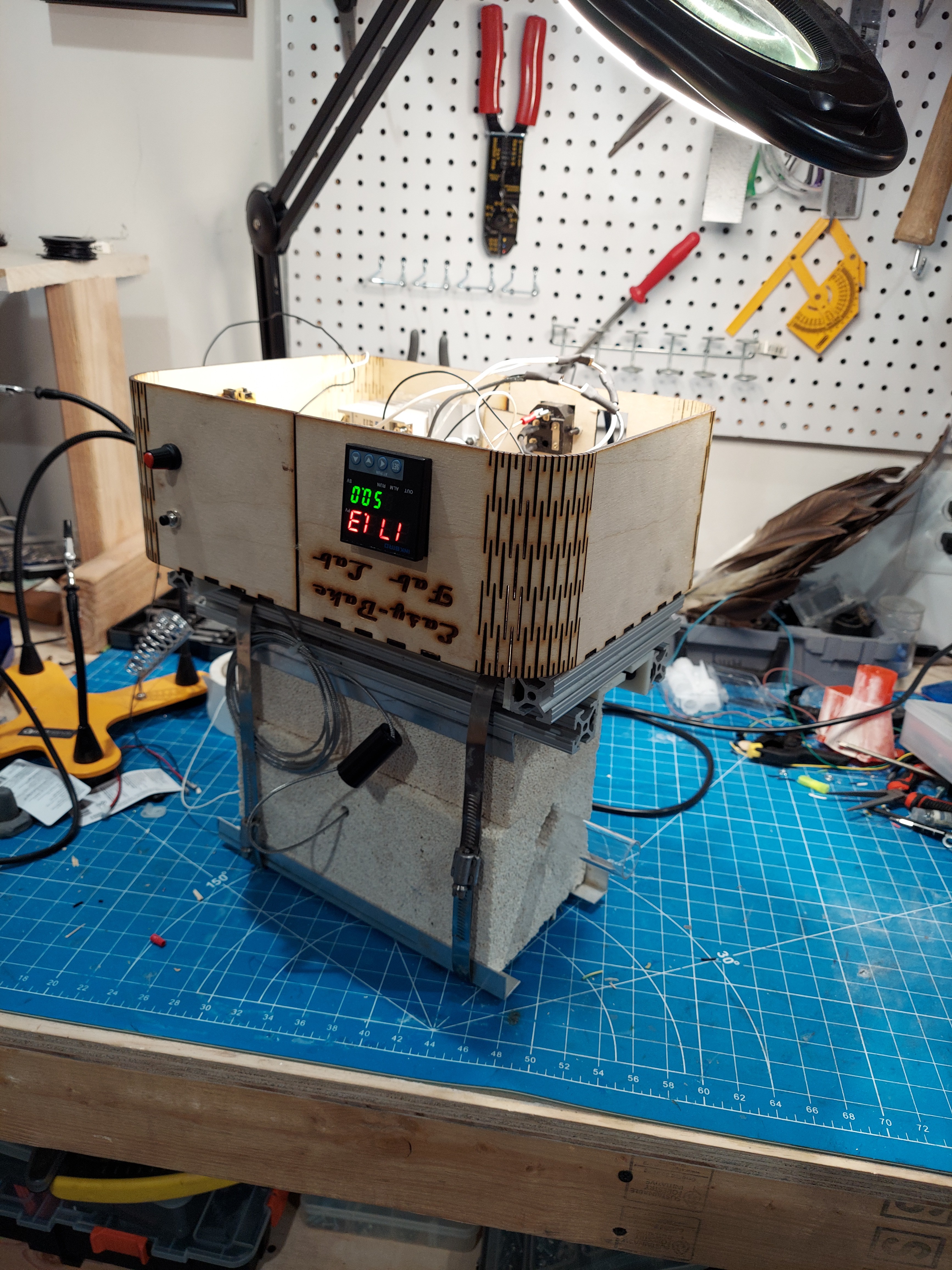
The actual electronics consist of the PID controller, power switch, 5v/12v power supply. Speed control for the fan and a button to activate the ultrasonic mister.
![]()
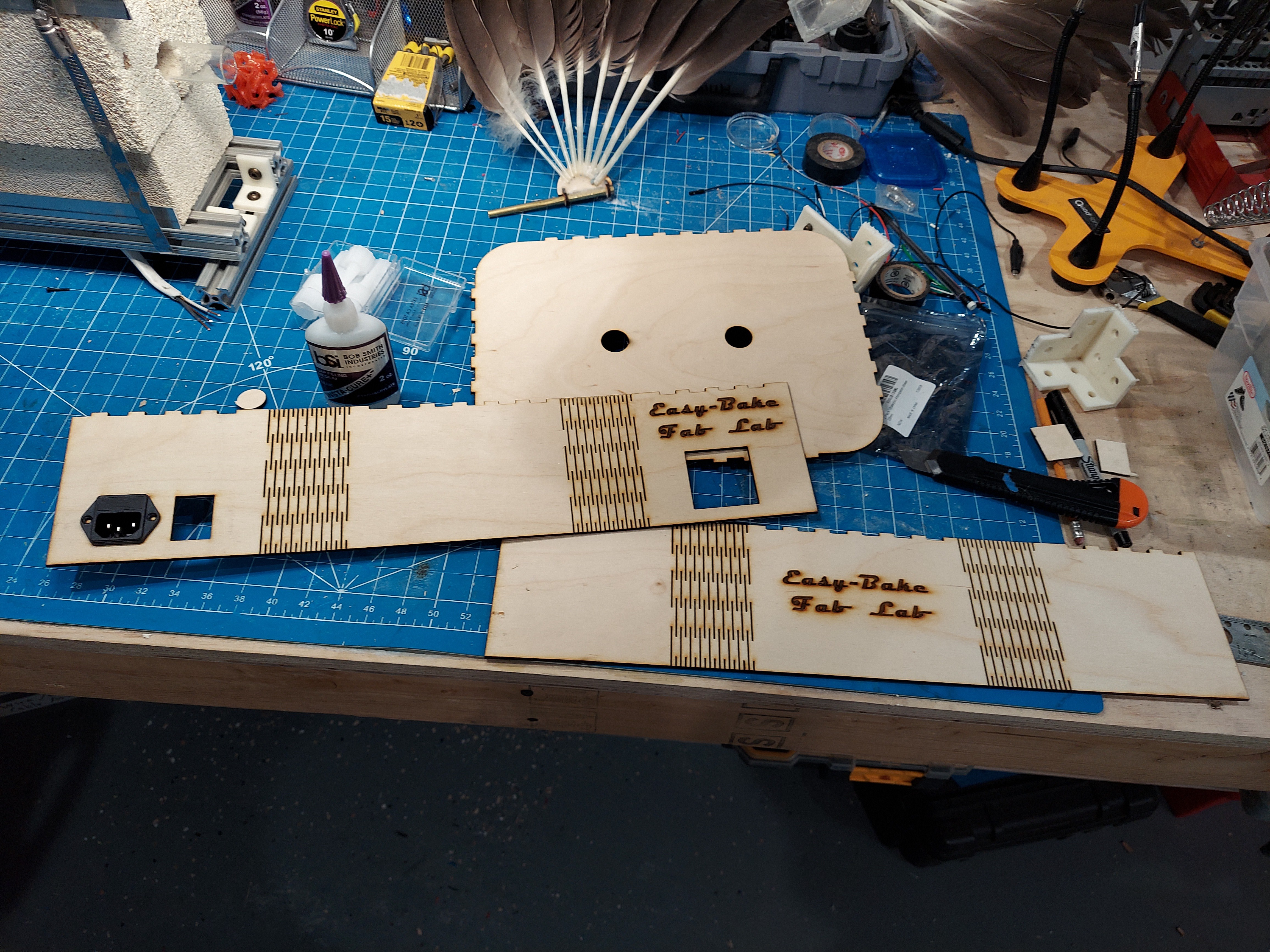
I re-used the same svg from my "Mr Pickles" project for the case. I added a few holes for the power, switch, PID Controller and more for the power connections on top.
![]()
Fully Assembled!
![]()
![]() Doing a little wiring. The Fan was connected to a speed controller and the Ultrasonic mister was connected to a button on the front panel.
Doing a little wiring. The Fan was connected to a speed controller and the Ultrasonic mister was connected to a button on the front panel.![]()
-
Building the Core
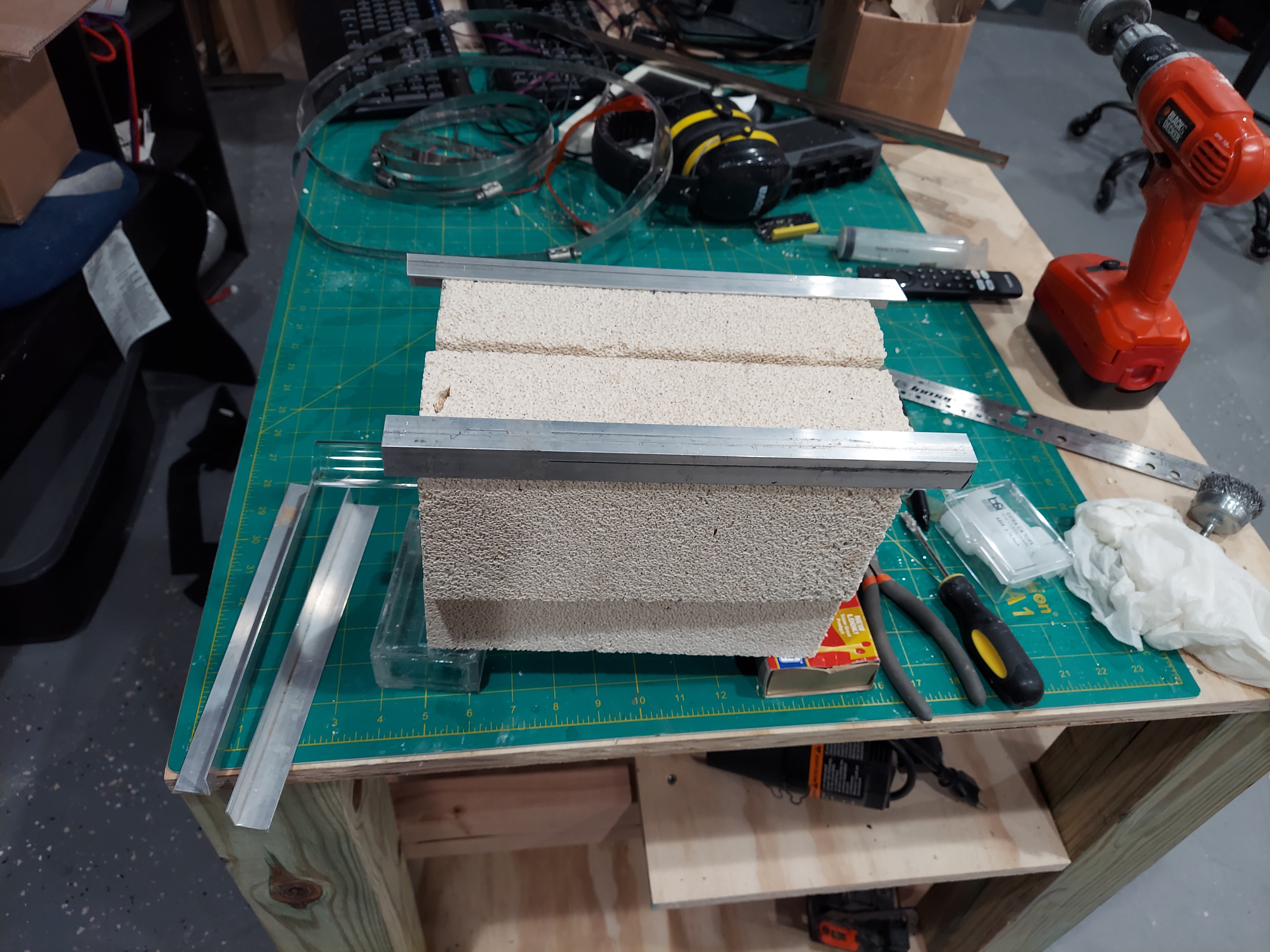
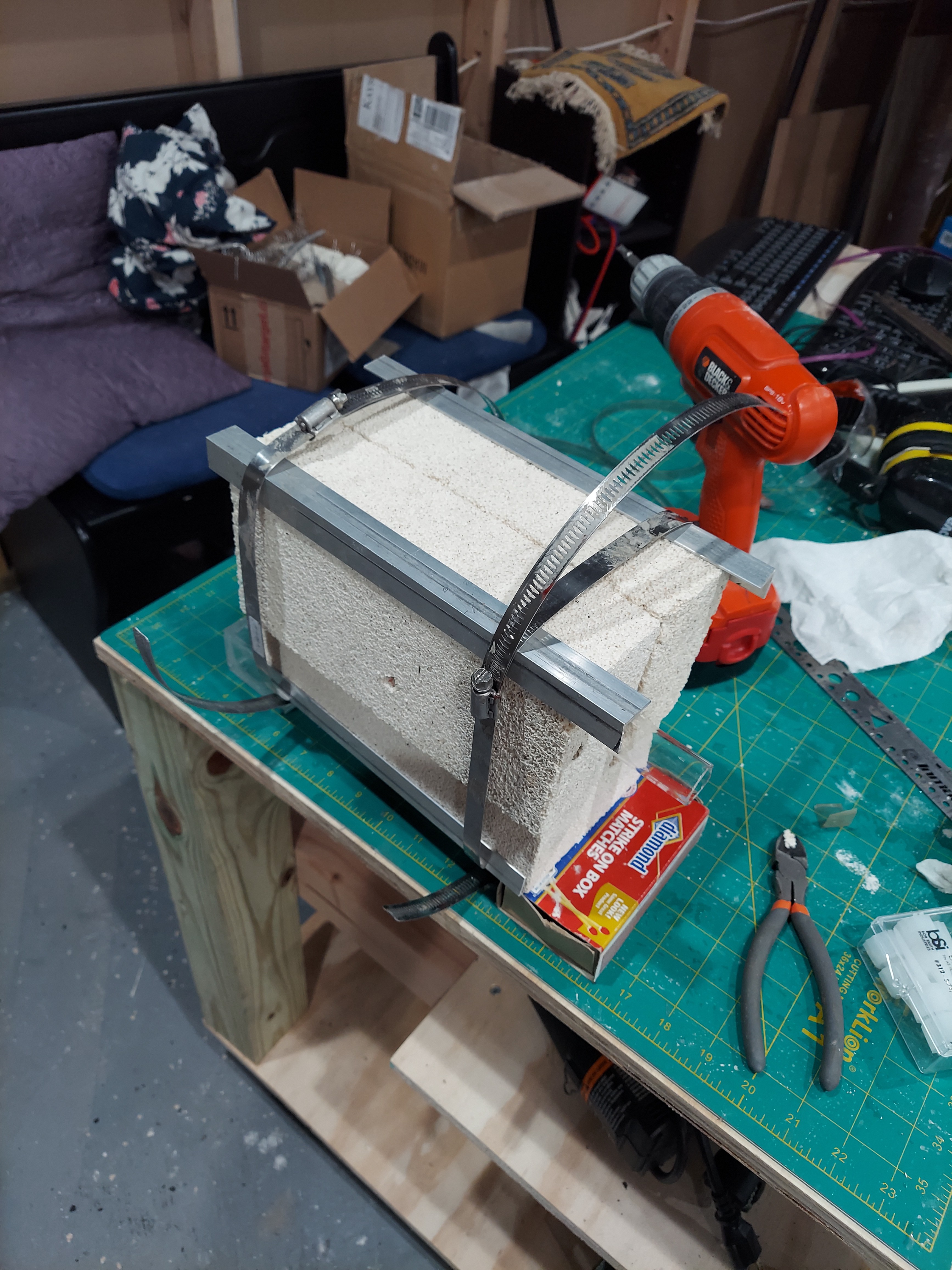
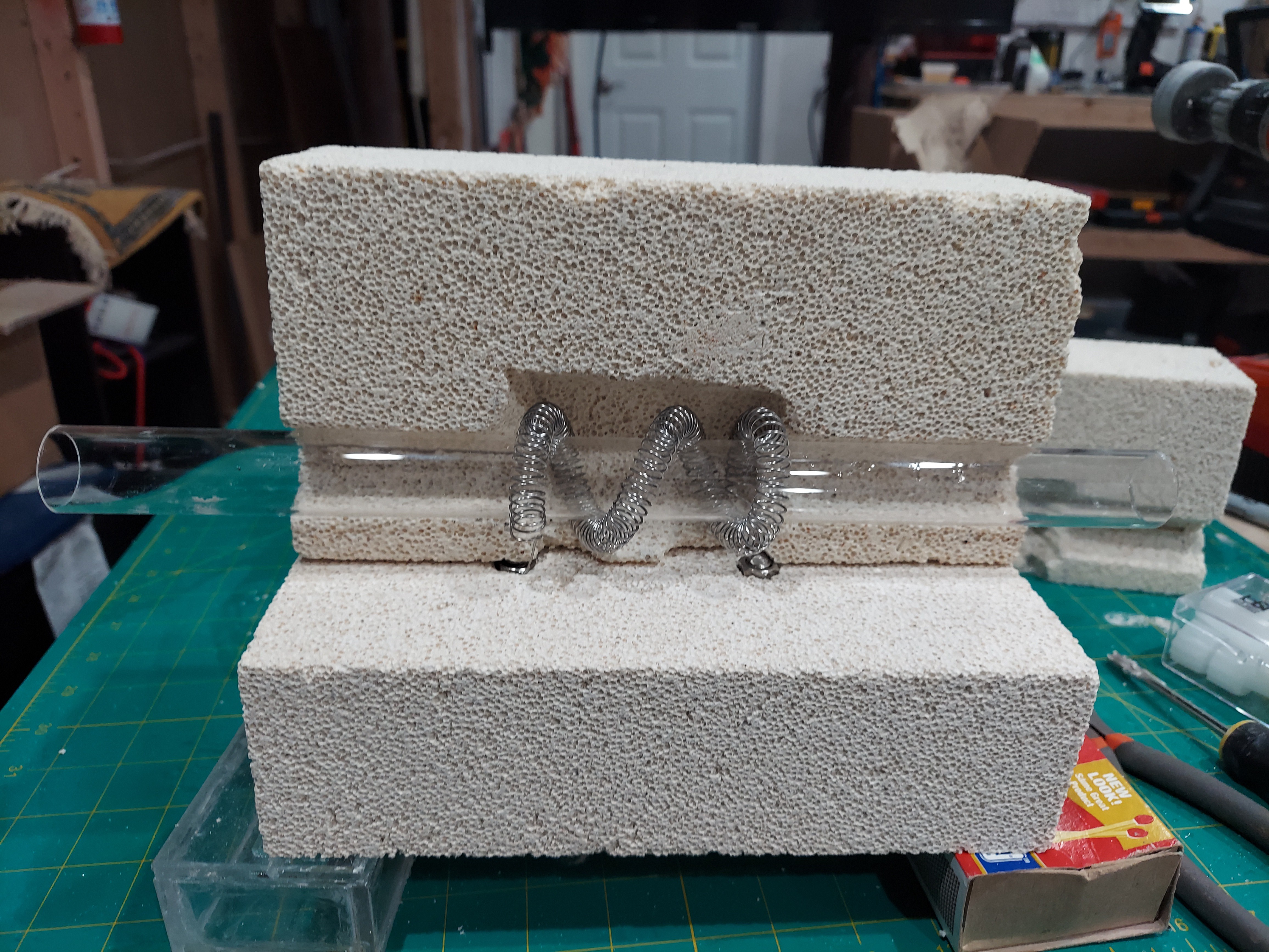
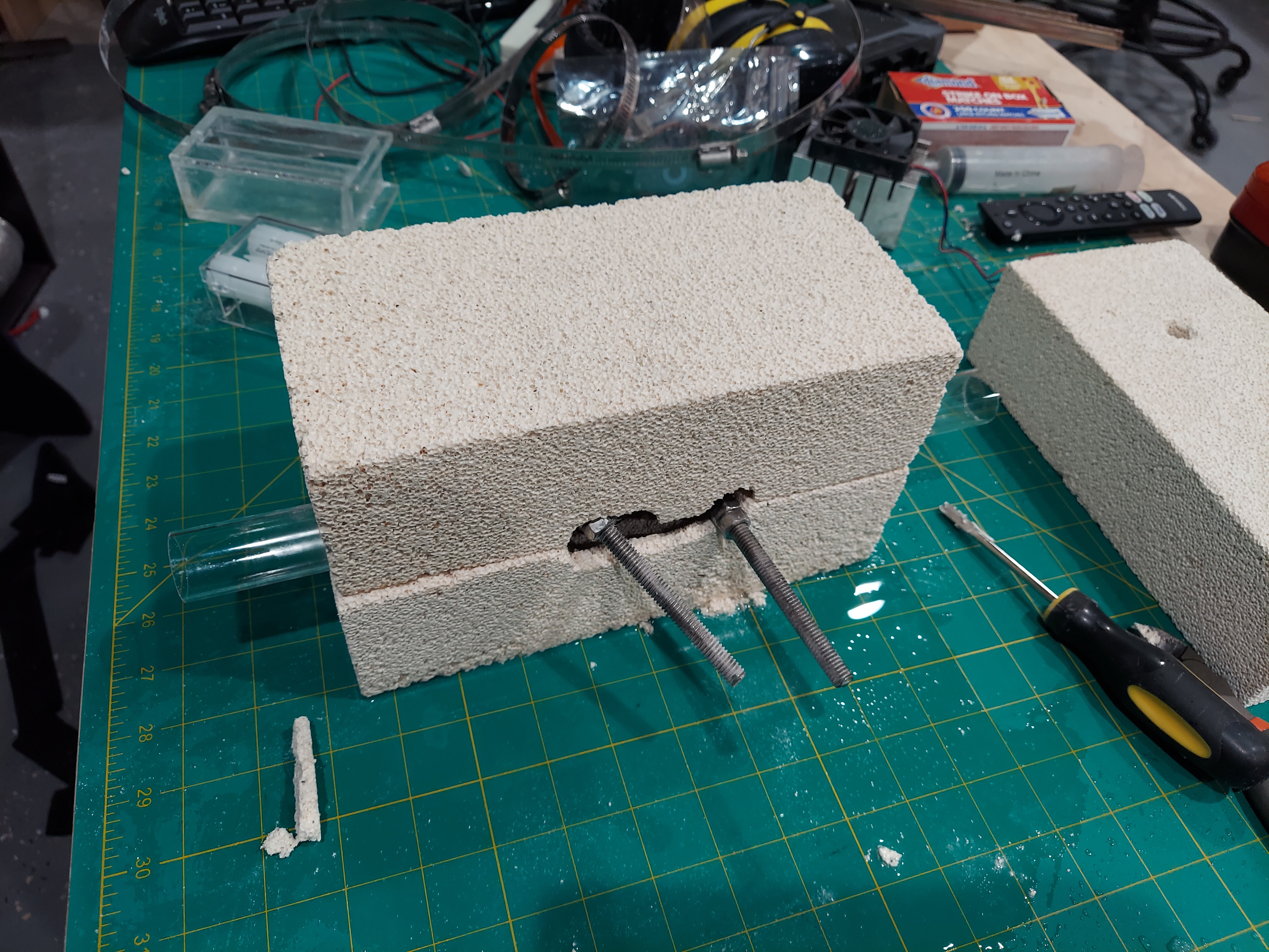
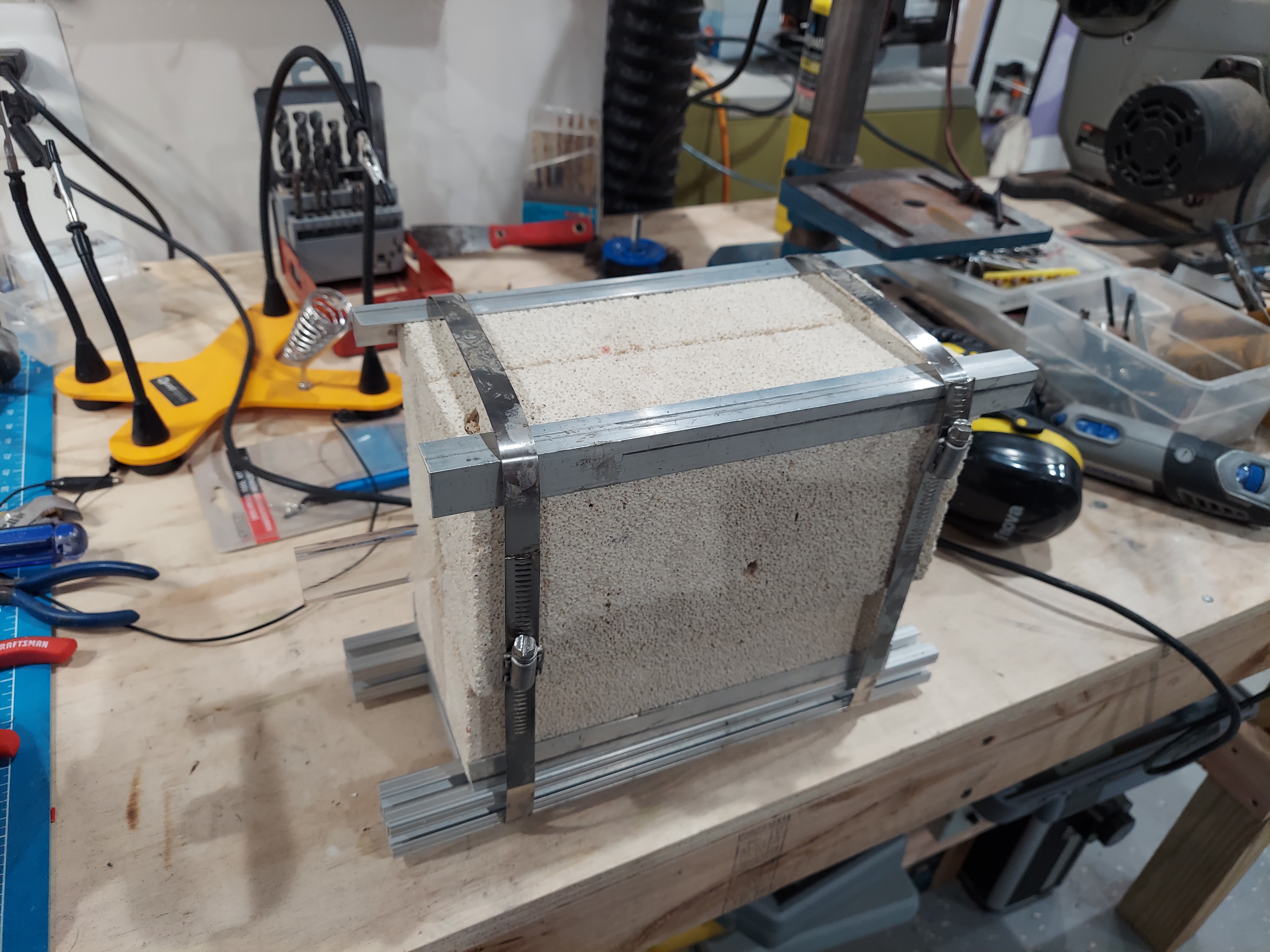
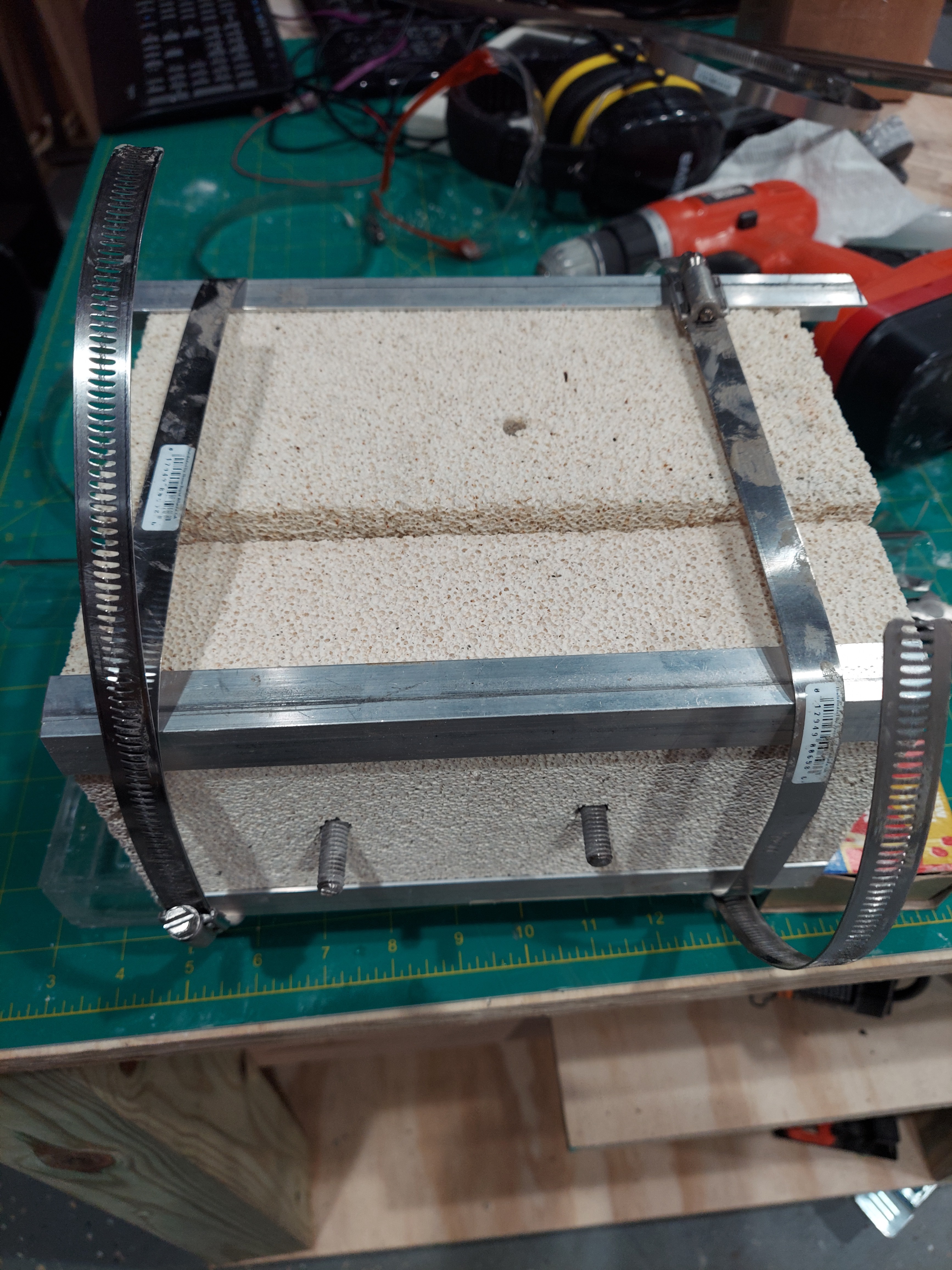
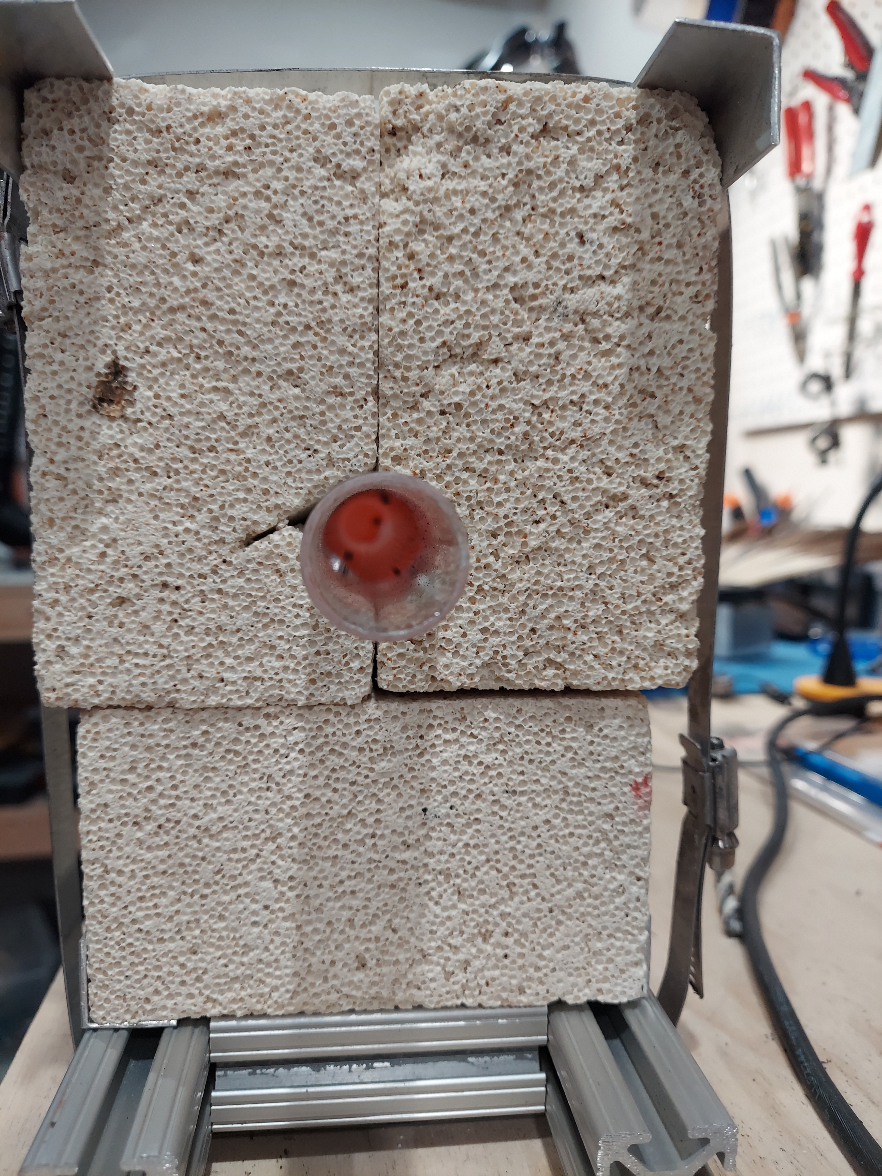
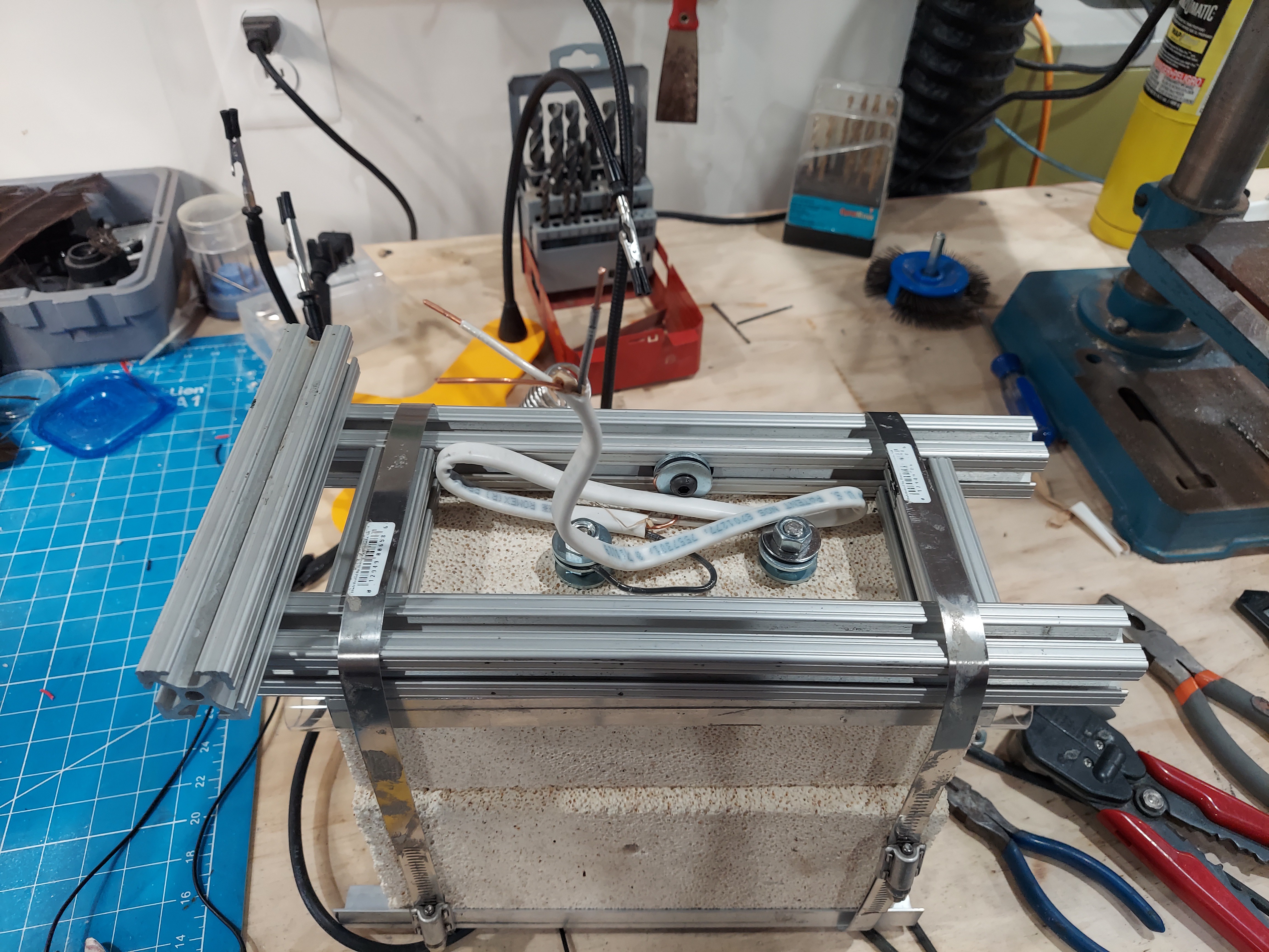
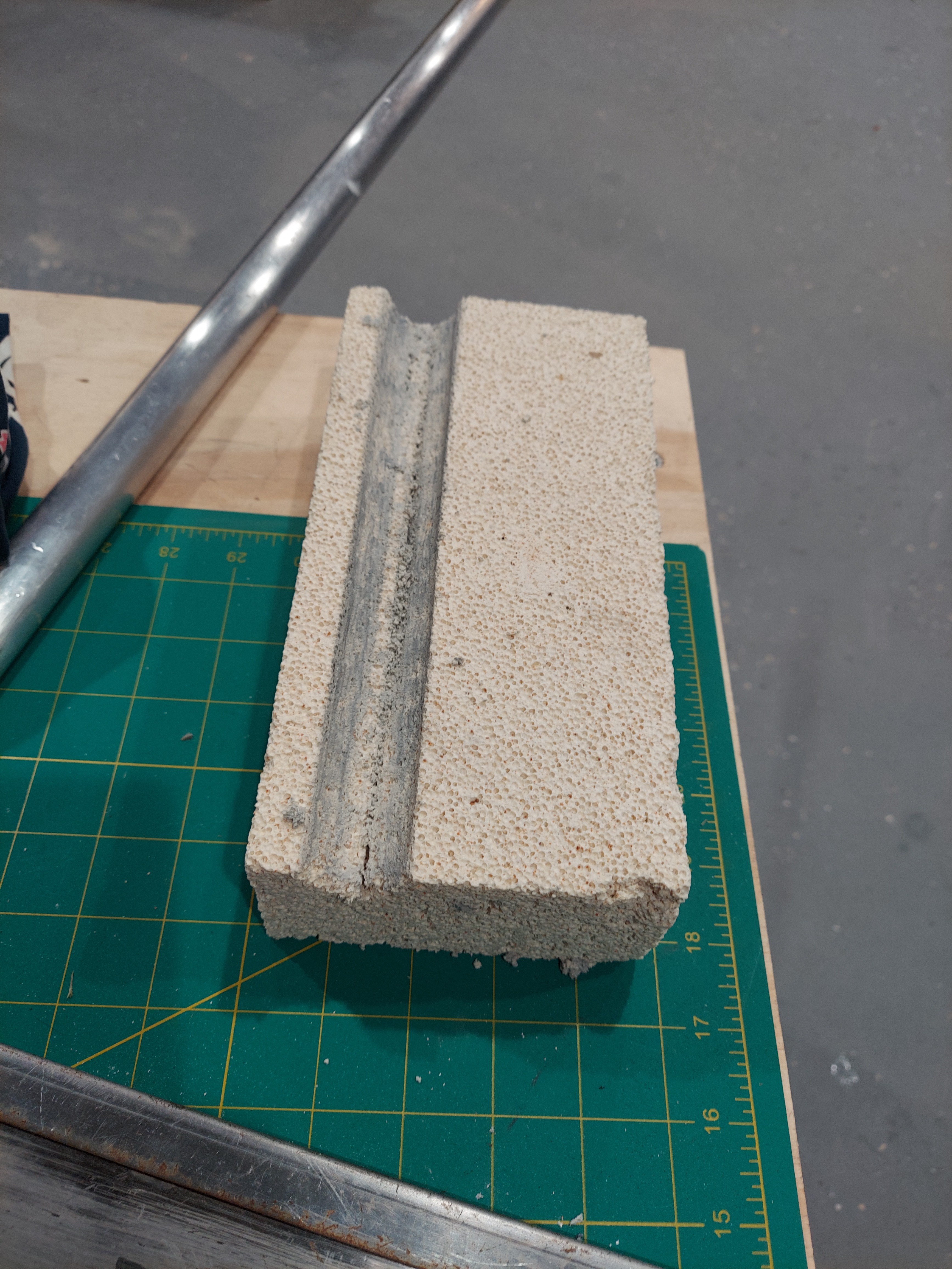
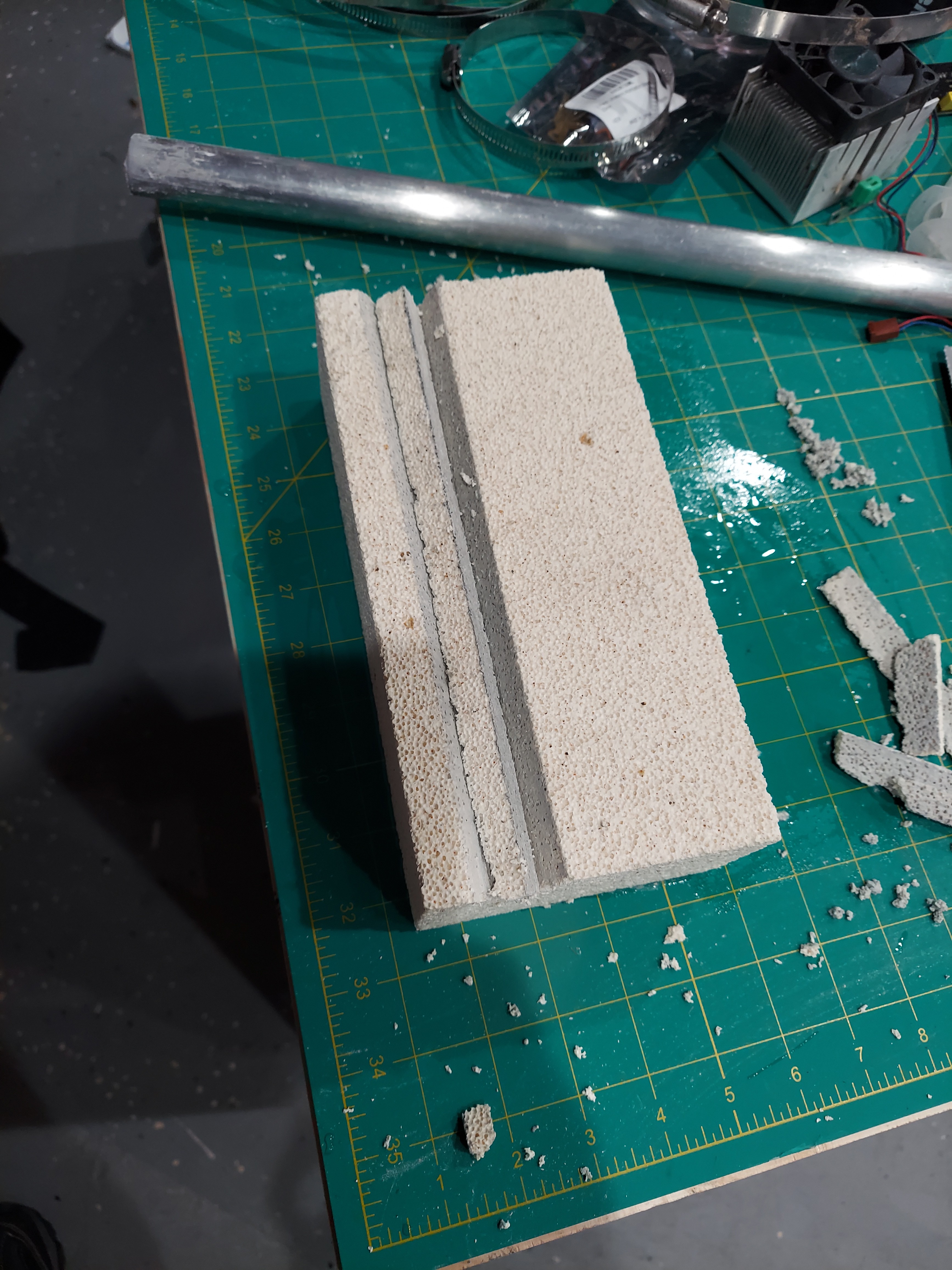
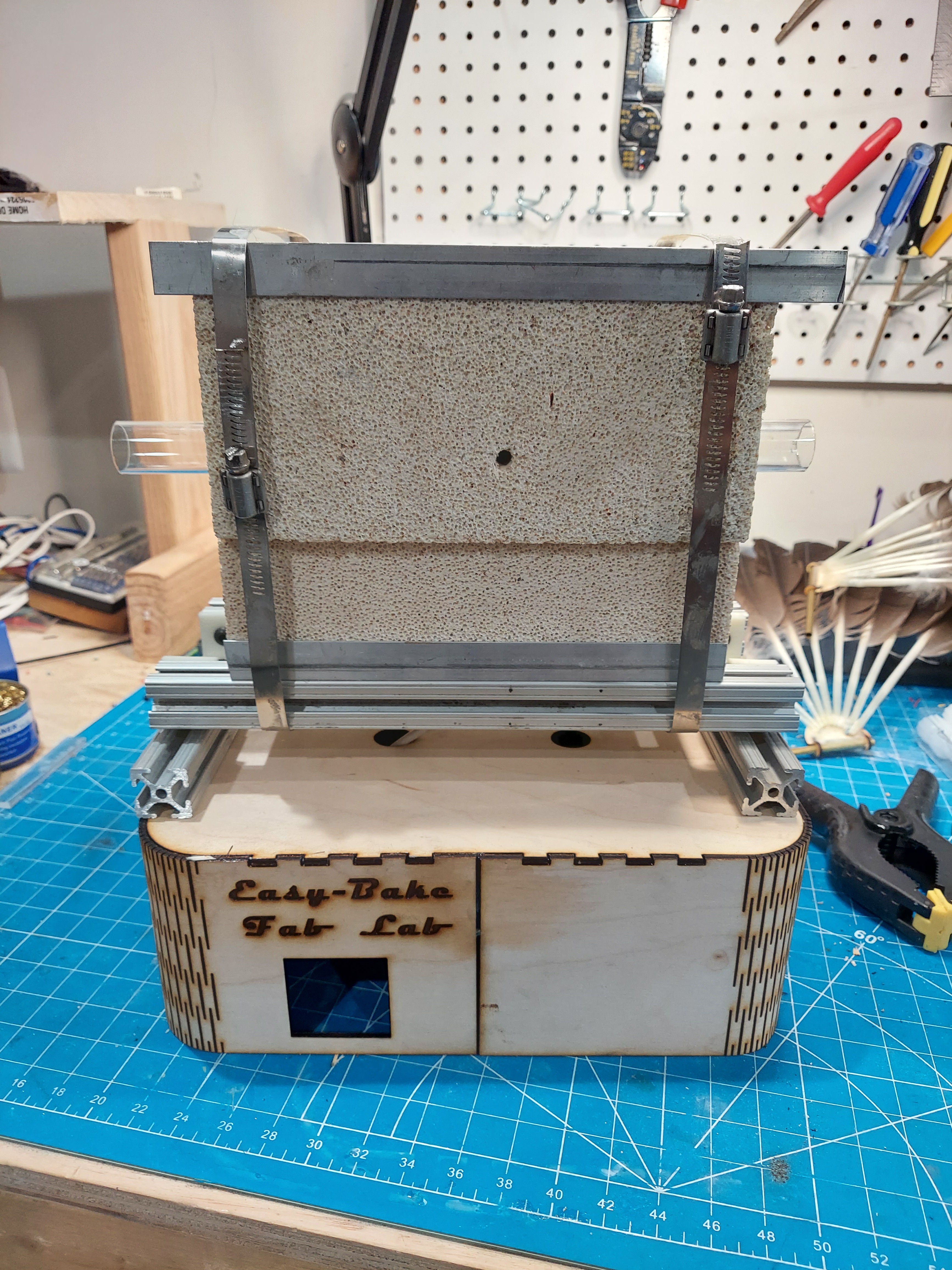
06/17/2022 at 00:56 • 0 commentsNow that the Kanthal is coiled and the glass is cut, I was able to assemble the heater core. I had some 4.5"x9" firebrick left over from a previous project, so that's what I used. I used 3 bricks. One brick acted as the support base and power pass-through and the other 2 bricks were used to clamshell around the quartz tube and heater wire. I used some aluminum L-bars, hose clamps and bar stocks to complete assembly. Note that the wire coil is only around the center 3". I finished it off with some aluminum framing extrusion. I wired the ground onto the frame and attached the white/black AC power to the steel bolts.
Caution - when working with firebrick - you should soak the bricks in water to prevent any dust while cutting.
![]()
![]()
![]()
![]()
![]()
![]()
![]()
![]()
![]()
![]()
![]()
![]()
-
Building the heater coils
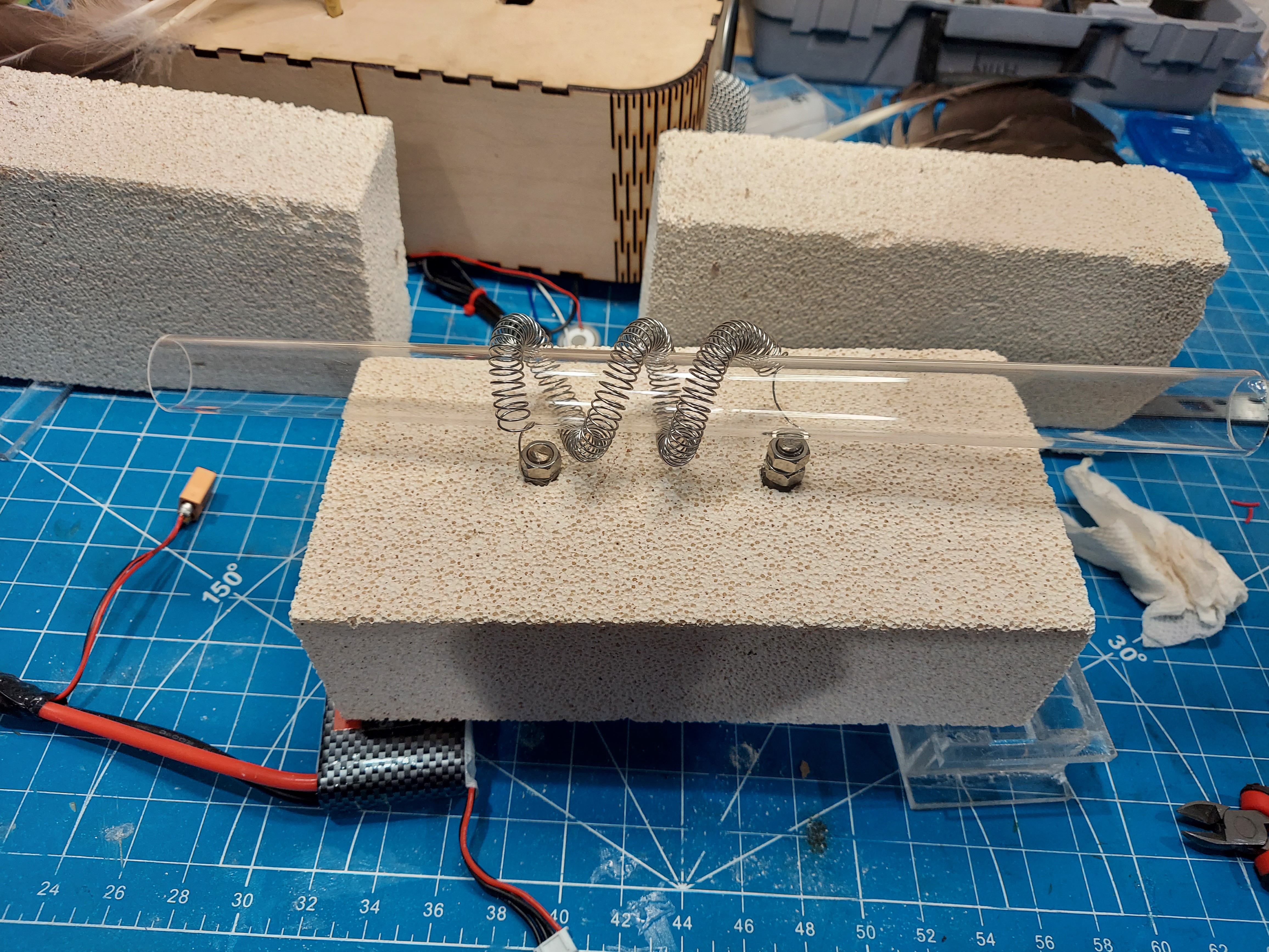
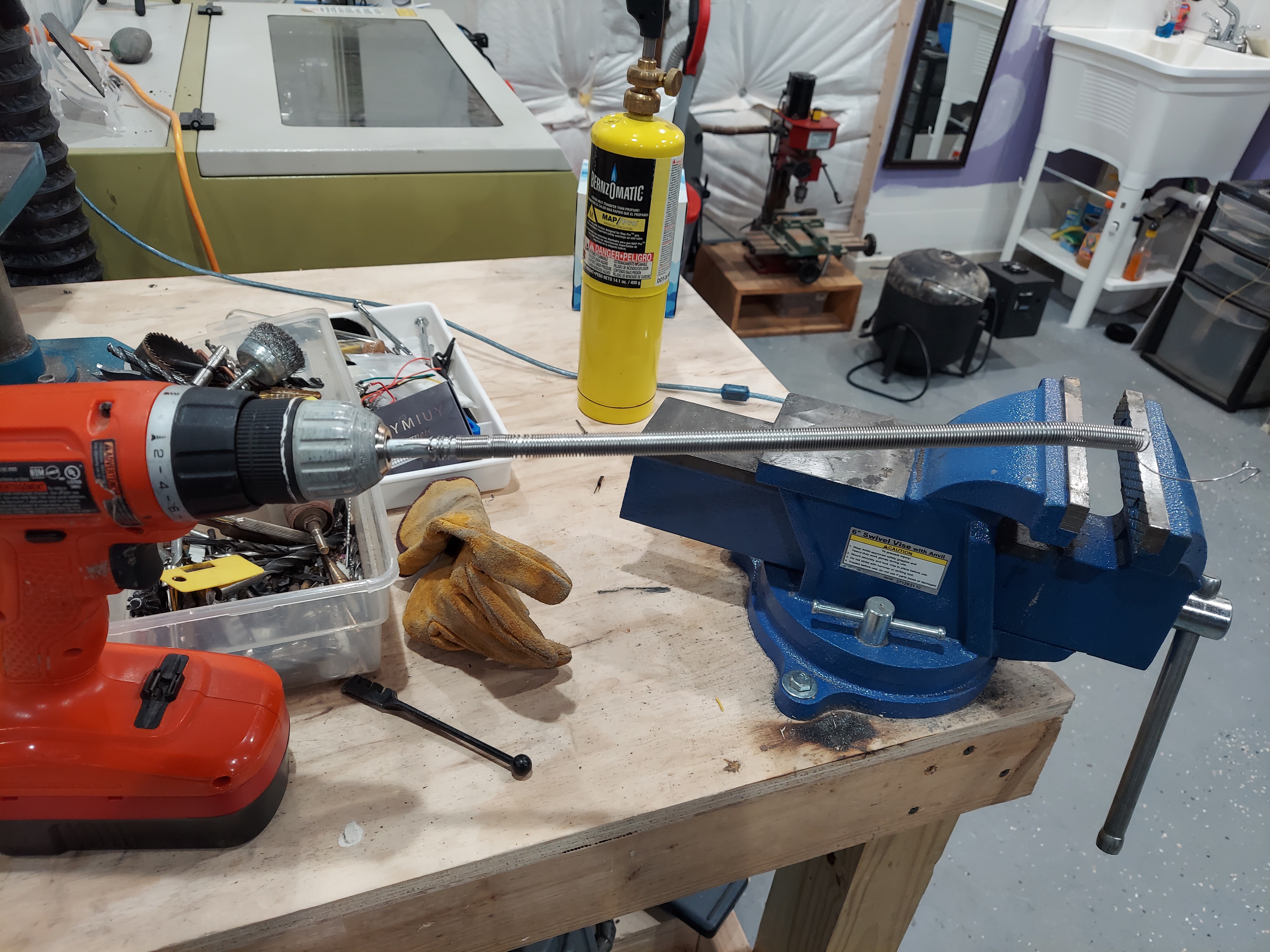
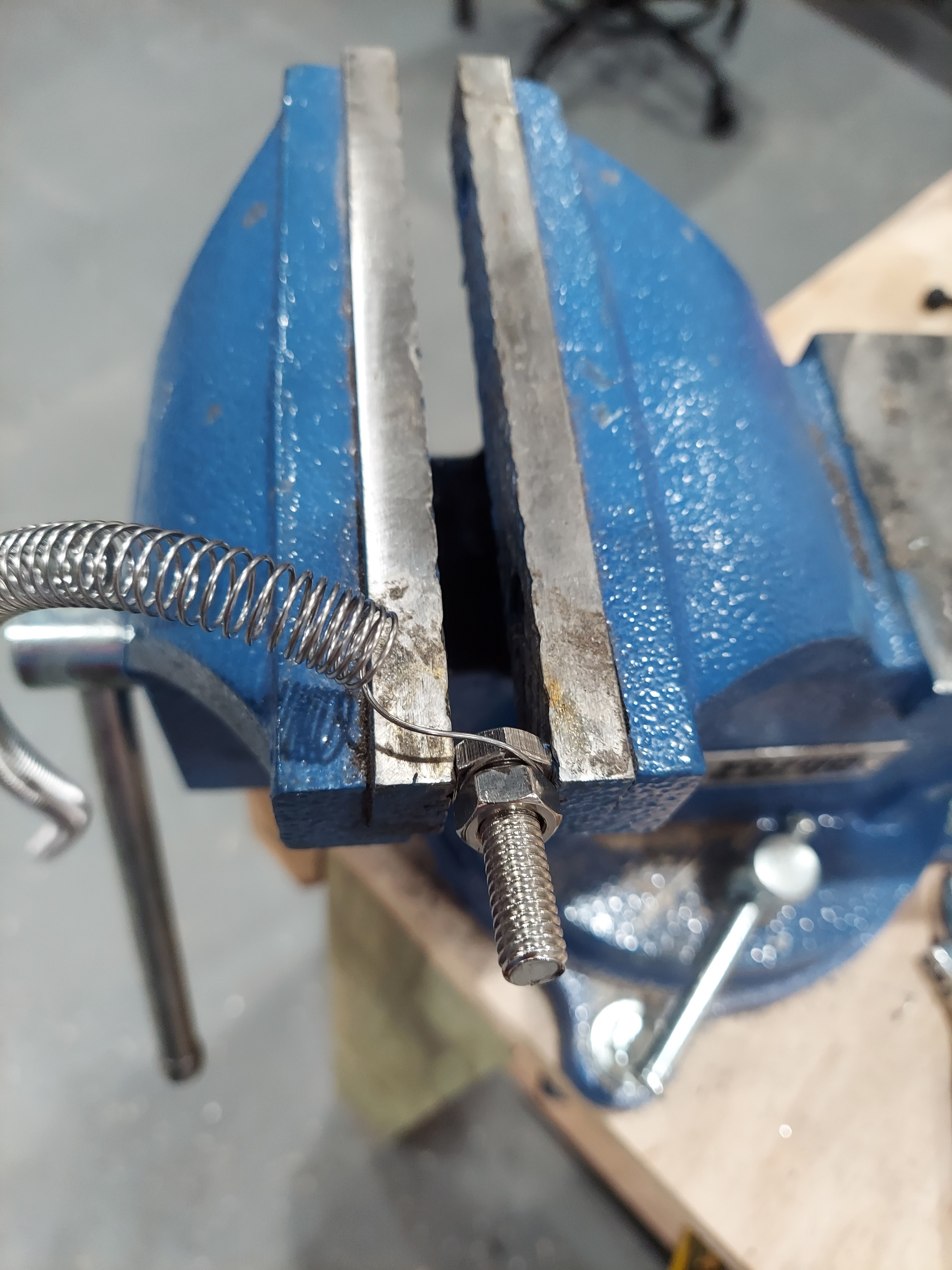
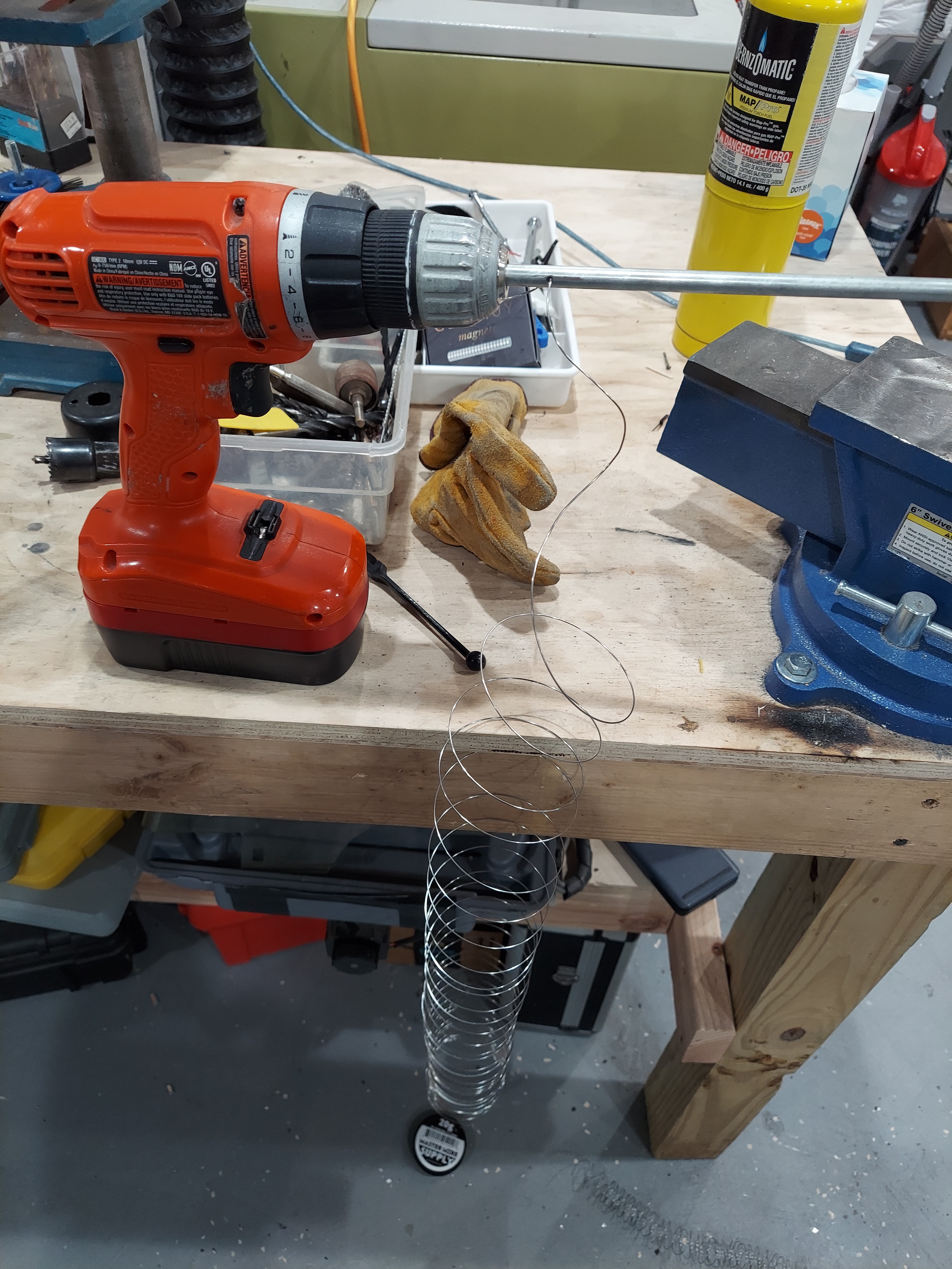
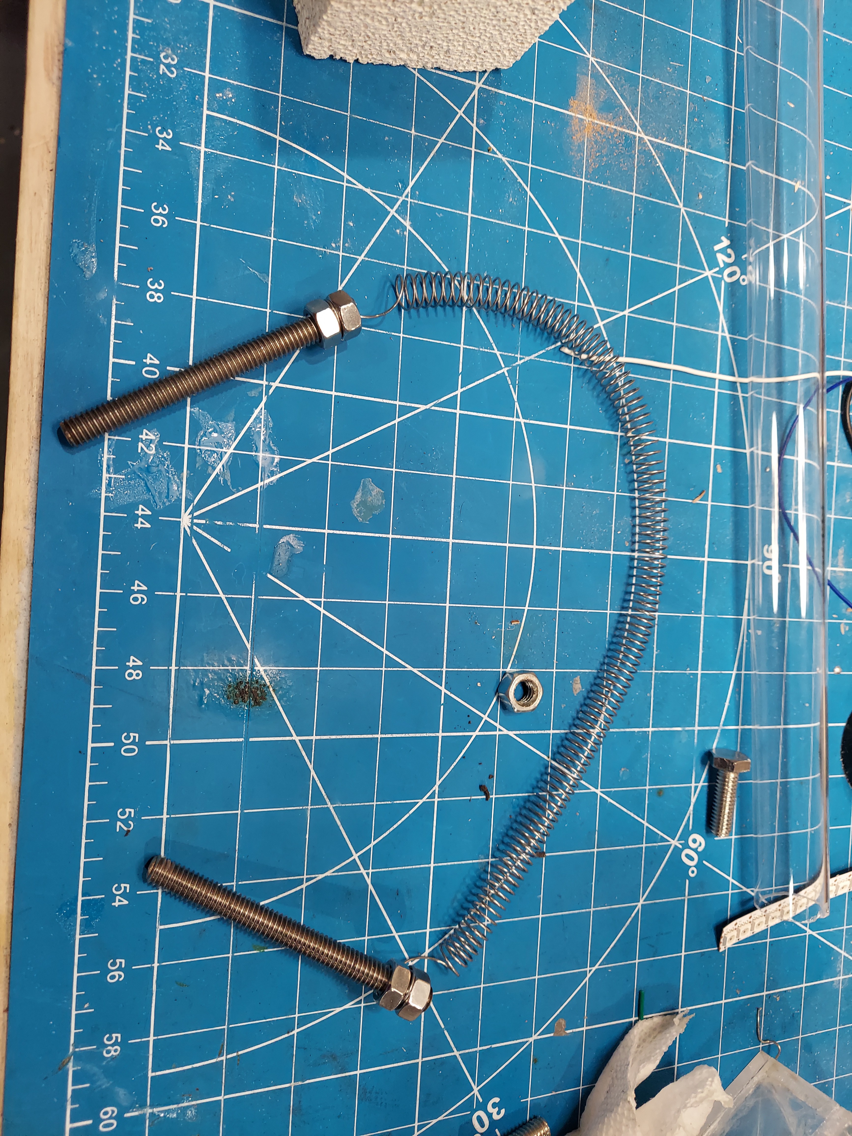
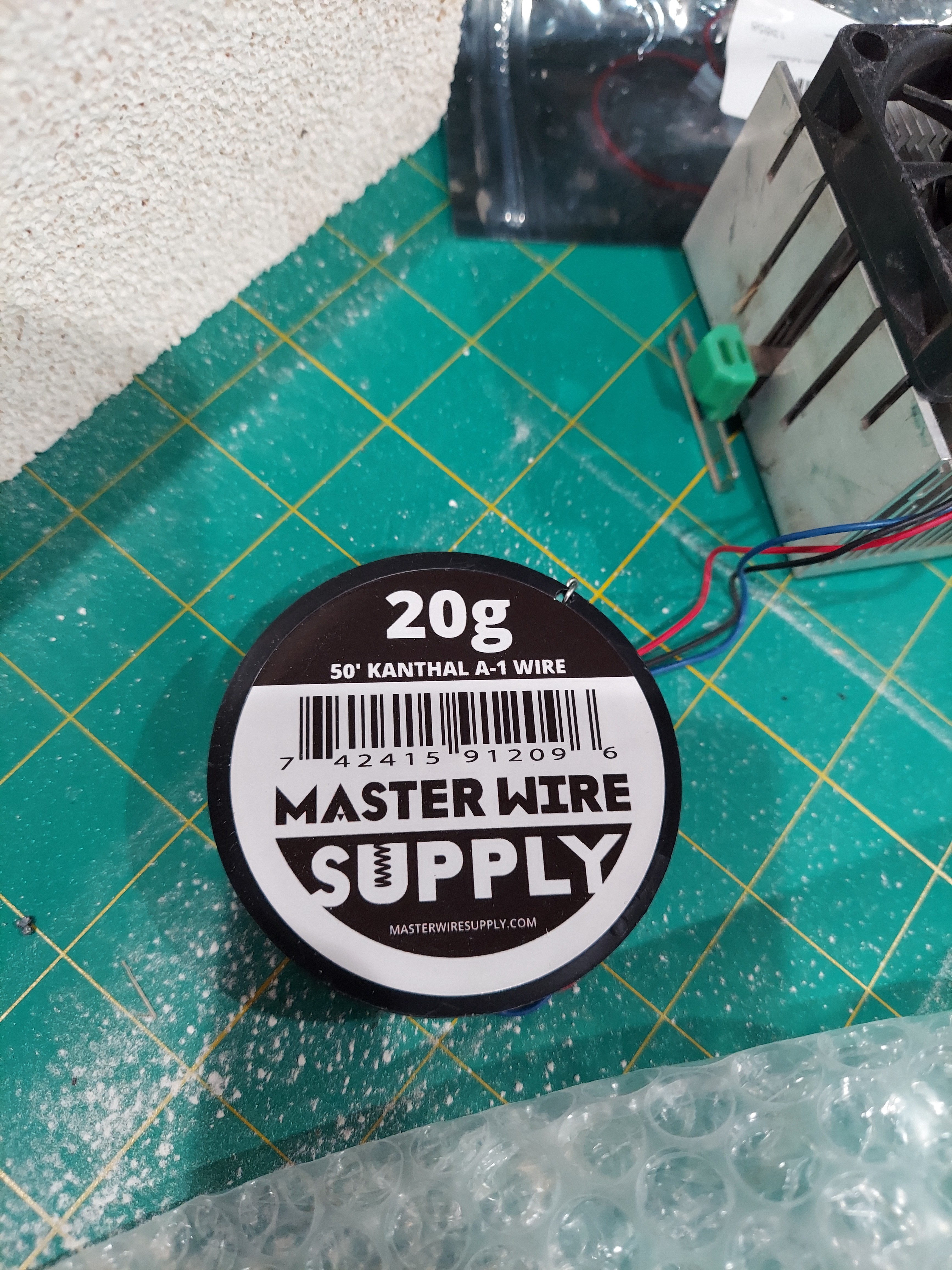
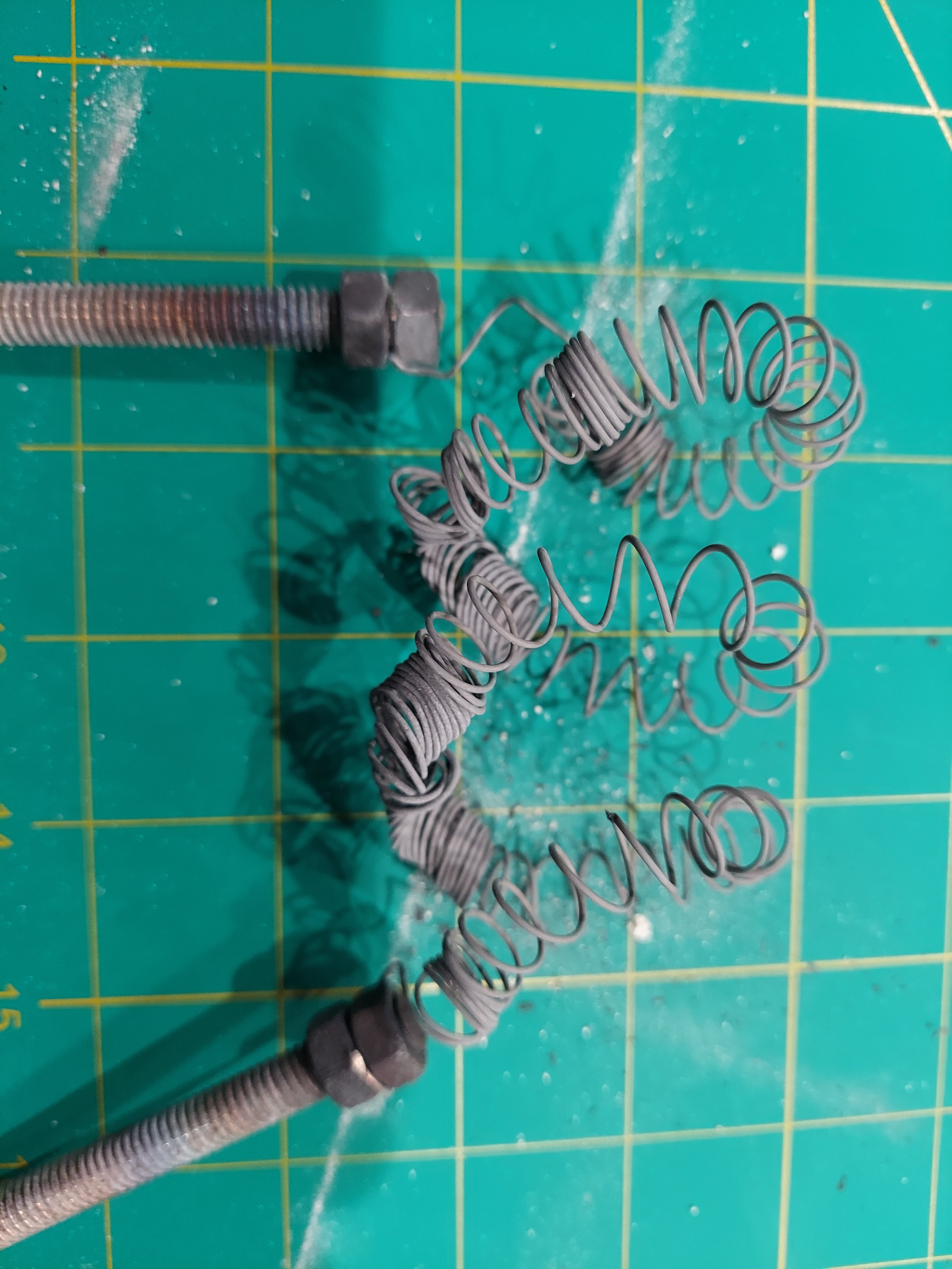
06/16/2022 at 13:12 • 0 commentsI chose Kanthal wire as the heater core element. I used a metal rod to coil it into a tight coil. I used stainless steel bolts to secure the ends and to use as an AC electrical connection. I was targeting a length of kanthal with a resistance around 11 ohms which provides about ~10.9 Amps of current for a total of 1.3KW of power.
![]()
![]()
![]()
![]()
![]()
-
Cutting the Quartz glass tube
06/16/2022 at 13:07 • 0 comments![]()
![]()
![]()
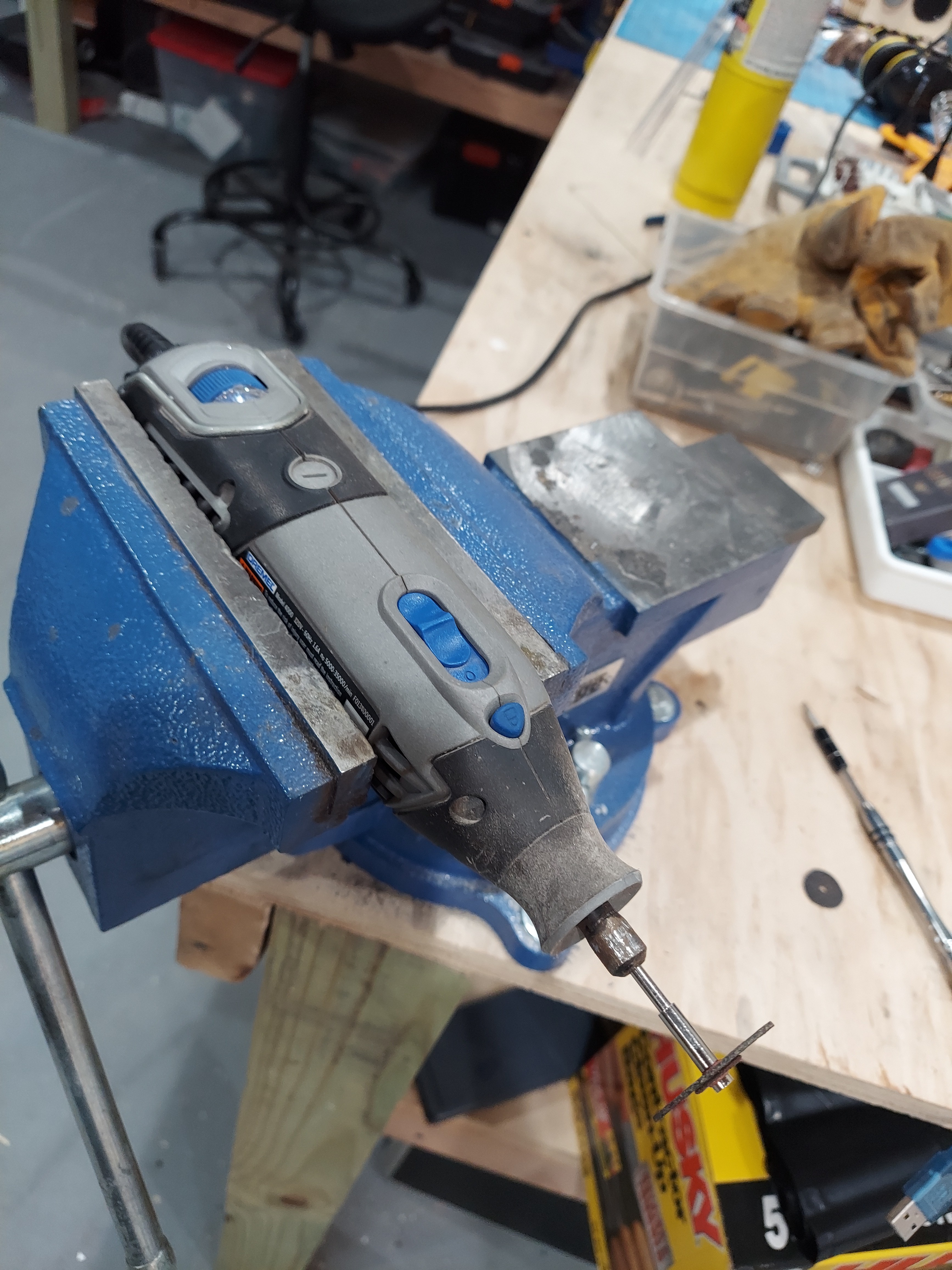
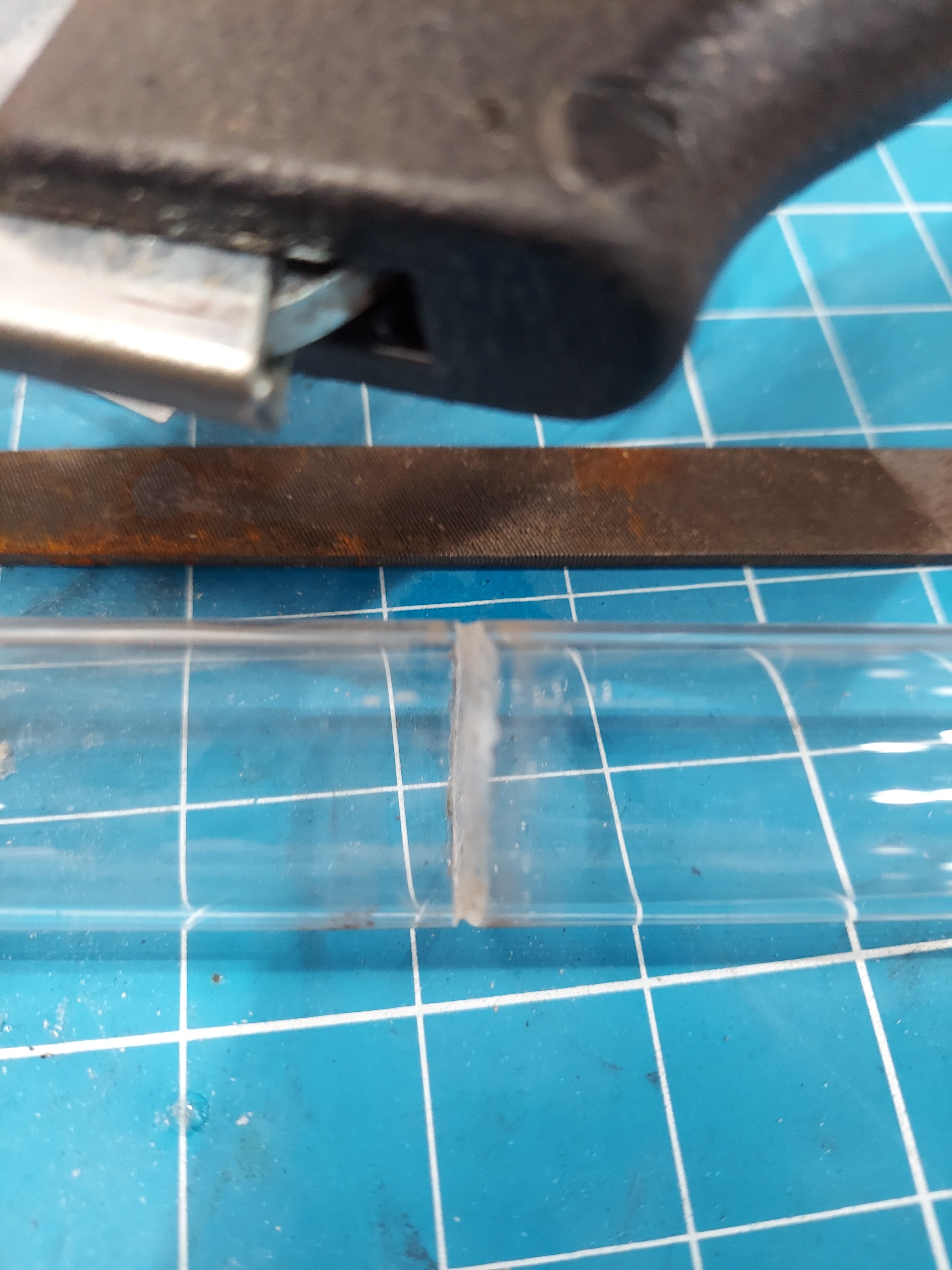
I had ordered a 1" quartz glass tube from Amazon. My tube was 4' long. I only needed a 13" section, so I had to cut it to length. Quartz glass can be tough to cut! After several unsuccessful attempts, I ended up scoring the tube with the glass cutter, then slowly rotating and cutting the tube using a rotary tool held in my vice. I rotated the tube over the cutter bit and slowly worked around the quartz tube until it was completely cut through.
Easy Bake Fab Lab
A study into building a semiconductor fabrication lab for the home hobbyist.
 Steve Hernandez
 Doing a little wiring. The Fan was connected to a speed controller and the Ultrasonic mister was connected to a button on the front panel.