 Hackhobby Labs
We need a few things to make our project. And here are they;
- 28byj-48 Stepper motor
- 10K Potentiometer
- Servo Motor 90g
- Push Button
- 1k ohm resistor
- ULN2003 Stepper motor driver
- Arduino Mega
- Power supply
- Material for Structure ( It can be anything like wood or 3d printed or if you want it to be affordable, use whatever you have, I used some kind of fiber plastic which is used for covering wood edges for furniture.)
28byj-48 Stepper Motor:
Stepper motors are commonly used in our daily used materials like they are in CD-ROMS, in AC cooling units, turntables, and so many other things,
They can have 4 or more 4 coils but basically, 4 coils in unipolar arrangement, and each coil are rated with 5 volts.
This motor has a stride angle of 5.625/64 degrees. The 64 here tells us that it takes 64 steps to complete one rotation and every step angle will be 5.625 degrees.
This motor does not provide High Torque as I mentioned earlier I made this just to show the working of the robotic arm and for some basic payload.
This motor has five wires at the output and if we look at its internal wire diagram we can see that four wires of color, Blue, Pink, Yellow, and Orange are for Four coils and the fifth wire is for +5volts.
To make the stepper motor work, we need to energize its coil alternatively and if we design a circuit then our working code should work according to something like this.
(refer to image)
Anyways, this was just for explanation, we will be using a library that eliminates this mess by handling it at the backend.
Making It:
Our robotic arm has three stepper motors at 3 axes.
- Stepper Motor 1 ----> At the base of our arm to give it rotation
- Stepper Motor 2 ----> The second joint after the base
- Stepper Motor 3 ----> The third joint
- Servo Motor ----> For the griper of the arm
And three potentiometers were used to control the positions of our motors. For the gripper motor I used two pushbuttons for two functions;
- Push Button 1 -----à Release ---à Will move the motor to 0 degree
- Push Button 2 -----à Grab -----à Will move the motor to 180 degrees
Base motor
The base motor was supported by two lids ( recovered from old storage containers)
The first lid had a hole to keep the motor in place and was glued together. The second lid had a hole to keep the coupler in place which was made from an old ballpoint. (Check the image attached above)
Second Motor
The second motor was glued with the 4 Cm piece of plastic attached to the base plate.
Third Motor
The third motor was glued to a 6cm piece of plastic which was attached to the second motor and exactly like other motors, this motor’s coupler was also made from Ballpoint.
The last servo motor aka the gripper was attached to the third motor via the same plastic material which was glued to the third motor.
The Griper
I used plastic from an old water bottle and made two holes then passed a piece of wire through them at one end I tied the wire to two freely moveable parts of plastic while another side of it was tied to a servo motor which was connected to the other side of the plastic.(It was exactly like the 3d model I made and attached above)
I couldn't get enough pictures from the build(only videos) that's why I explained them exactly like they were through the 3D model using TnkerCad.
-------------------------------------------------------------------------------------------------------------------------------------------------------------
(I have uploaded the STL file here and I have attached a Link to tinkercad but if you want to 3d print it then you'll have to resize it and maybe some modifications too, cause I made it just to visualize my robot.
Code and Schematics:
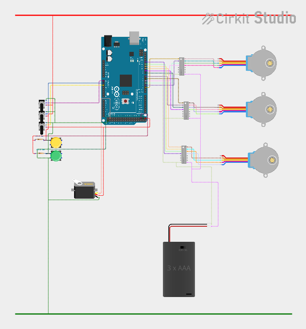
Circuit Scheme is really simple and everything was connected to Arduino as it's defined in code.
Components like;
- Potentiometers
- Push Buttons
- Servo motor
were powered directly from Arduino 5v...
Read more »
 hIOTron
 Frank Herrmann
 Dave Ehnebuske