 utsourceproduct
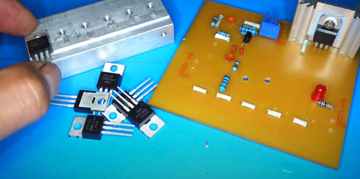
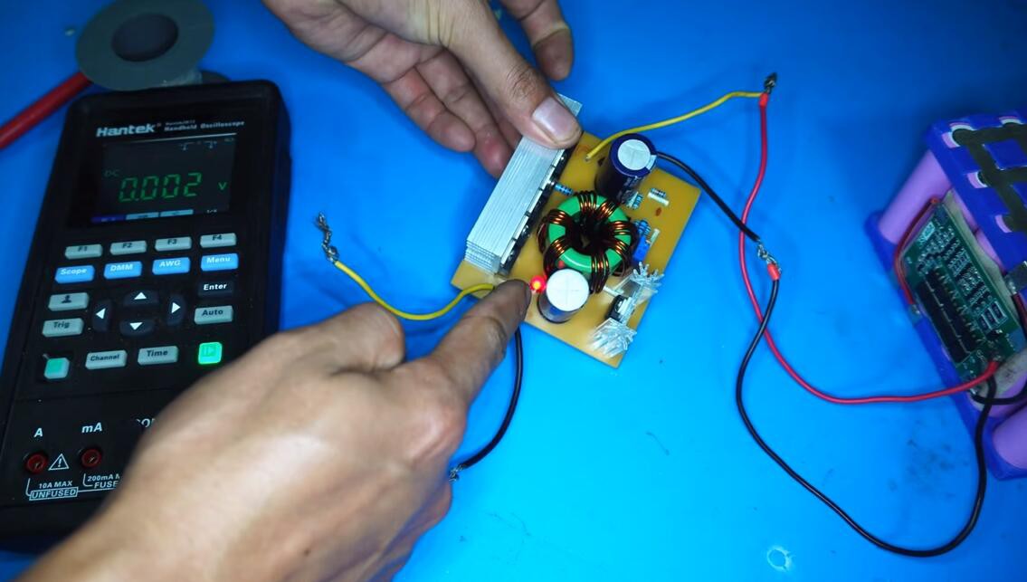
Today I will show to how to make How to make 500W Step up converter
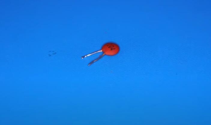
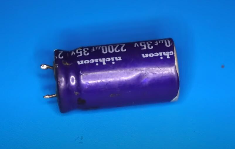
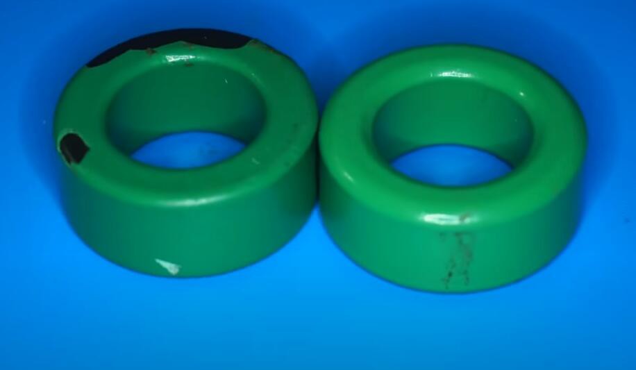
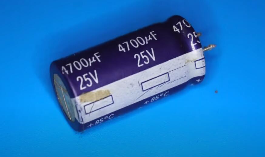
All the material you need for this project:

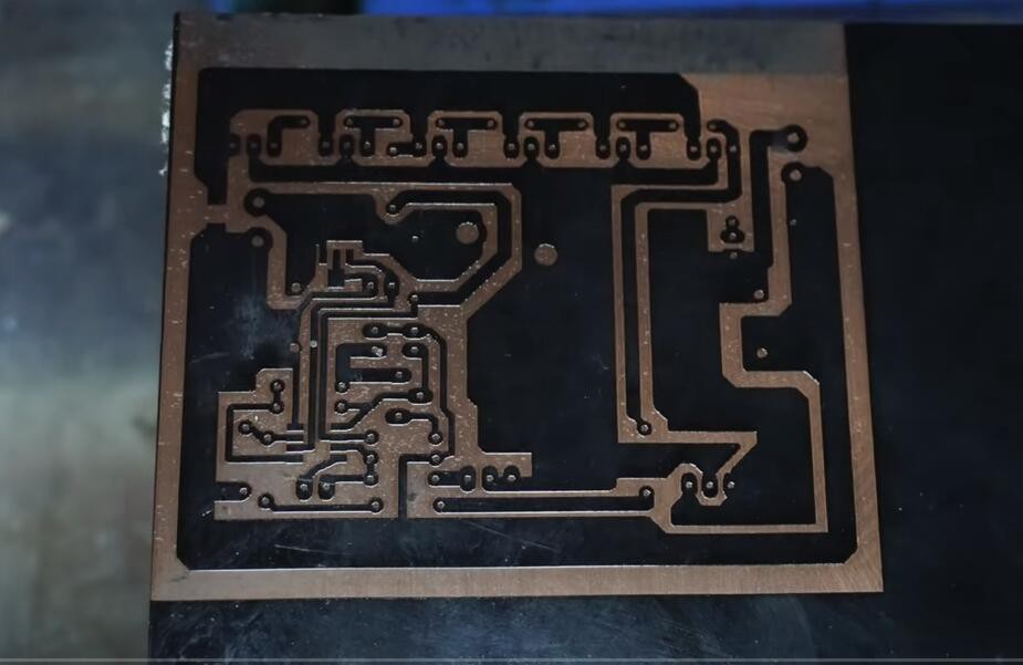
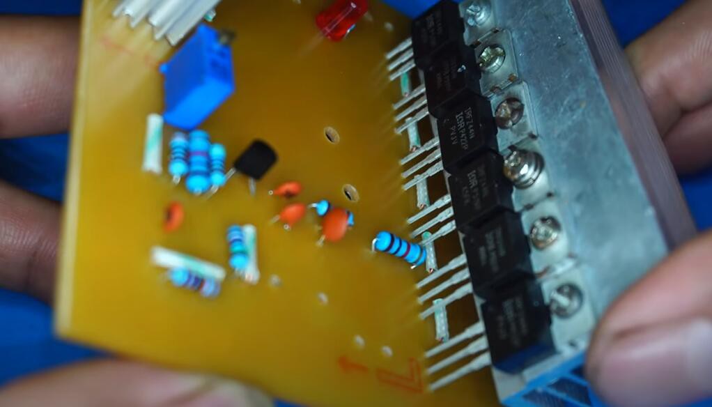
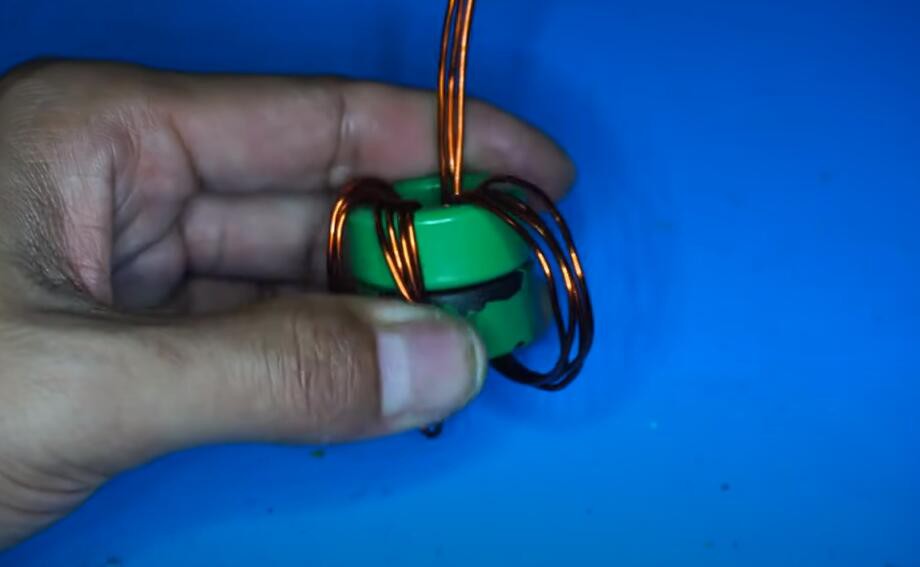
Here are the steps of this project:
1.
2.
3.
4.
5.
6.
7.
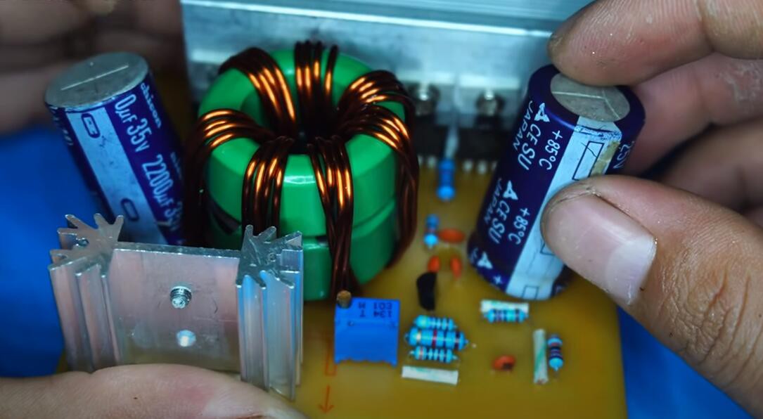
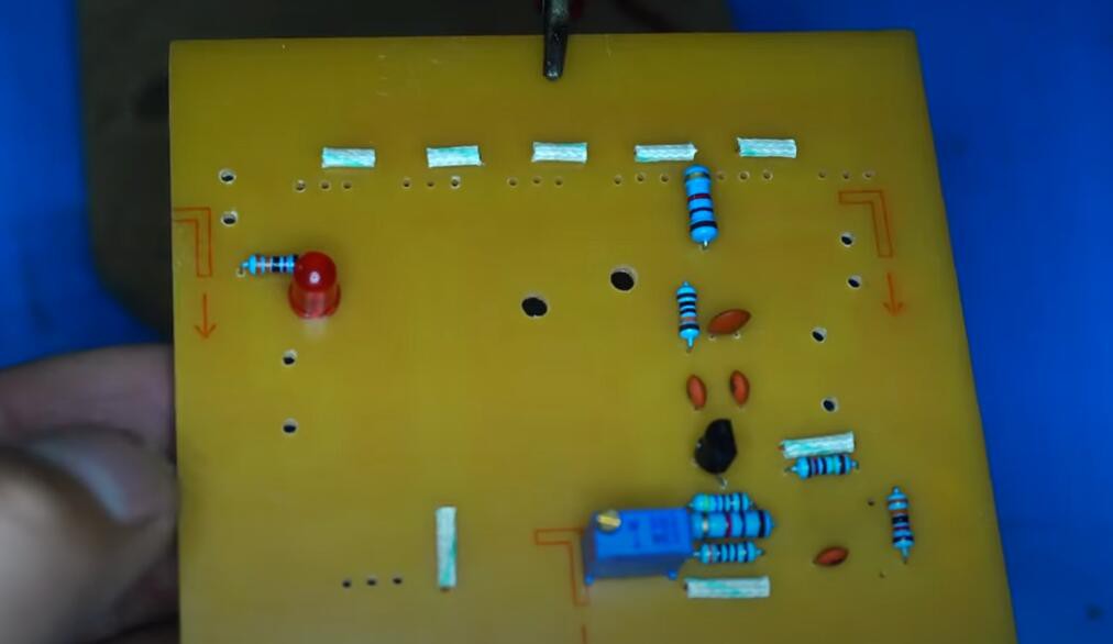
Show results:
The product links as below:
IC chips: https://www.utsource.net/category/ele...
Modules: https://www.utsource.net/Modules?sour...
Passive components: https://www.utsource.net/PassiveDevic...
Sensors: https://www.utsource.net/home/sensors...
LED lightings: https://www.utsource.net/category/led...
More electronic components you may be interested:
VIPER22A https://www.utsource.net/itm/p/11226780.html
Product Attributes
Not found, similar datasheet recommended
Description
The VIPer22A combines a dedicated current mode PWM controller with a high voltage Power MOSFET on the same silicon chip. Typical applications cover off line power supplies for battery charger adapters, standby power supplies for TV or monitors, auxiliary supplies for motor control, etc.
Features
● FIXED 60 KHZ SWITCHING FREQUENCY
● 9V TO 38V WIDE RANGE VDD VOLTAGE
● CURRENT MODE CONTROL
● AUXILIARY UNDERVOLTAGE LOCKOUT WITH HYSTERESIS
● HIGH VOLTAGE START UP CURRENT SOURCE
● OVERTEMPERATURE, OVERCURRENT AND OVERVOLTAGE PROTECTION WITH AUTORESTART
IR2110 https://www.utsource.net/itm/p/11537319.html
Product Attributes
The IR2110/IR2113 are high voltage, high speed power MOSFET and IGBT drivers with independent high and low side referenced output channels. Proprietary HVIC and latch immune CMOS technologies enable ruggedized monolithic construction. Logic inputs are compatible with
standard CMOS or LSTTL output, down to 3.3V logic. The output drivers feature a high pulse current buffer stage designed for minimum driver cross-conduction. Propagation delays are matched to simplify use in high frequency applications. The floating channel can be used to drive an N-channel power MOSFET or IGBT in the high side configuration which operates up to 500 or 600 volts.
Features
● Floating channel designed for bootstrap operation Fully operational to +500V or +600V Tolerant to negative transient
voltage dV/dt immune
● Gate drive supply range from 10 to 20V
● Undervoltage lockout for both channels
● 3.3V logic compatible Separate logic supply range from 3.3V to 20V Logic and power ground ±5V offset
● CMOS Schmitt-triggered inputs with pull-down
● Cycle by cycle edge-triggered shutdown logic
● Matched propagation delay for both channels
● Outputs in phase with inputs
What is IR2110
IR2110 is a MOSFET gate driver IC that can used to drive high and low side configurations. Usually to drive two MOSFETs in half bridge or high and low side configuration we will need complicated driver circuit with complementary transistors dual voltage supplies and lots of other complementary devices such as resistors, capacitors and diodes. However, we can achieve the same function using IR2110 MOSFET driver IC only using few other complementary components. You can see the physical appearance of the IR2110 MOSFET driver IC in below image.
Pinout of IR2110:
IR2110 MOSFET driver IC comes in a 14 pin DIP package and a 16 pin SOIC package. In below image pinout of the 14 pin DIP packaged IR2110 IC is given.
SupplierFile/202005/19/f_4d183d72de624310bc79add094367663.png
Figure 3. – Pinout of IR2110
Lets identify the pin functions and more details on each pin of IR2110
· Pin 1 – LO – Low side MOSFET gate output pin
· Pin 2 – COM – Low side return pin or the MOSFET common pin.
· Pin 3 – VCC– Voltage supply for the gate voltage.
· Pin 4 – NC – Not connected
· Pin 5 – VS – High side floating voltage supply return pin
· Pin 6 – VB – High side floating voltage supply pin
· Pin 7 – HO – High side MOSFET gate output...
Read more »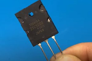
 UTSOURCE
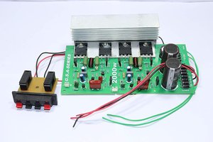
 engineerkid1
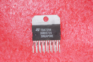
 Electroniclovers123
 Adrian Freed