 Jovan
JovanThis project will be a clean hack of the otherwise very solid ART DJ-Pre II phono preamp with the aim of improving the existing design and enhancing its features
This project will follow my experience and guidelines developed while working on the development and improvement of a commercial product (in my private ownership) without prior knowledge or information and specifications obtained from the manufacturer.
The need to make the device in my private ownership better will be publicly available and in accordance with the EU directives related to the requirement for manufacturers to make their products serviceable, therefore I disclaim in advance and reject any responsibility in the event that some part of the solution is publicly interpreted and clarified and in interest of us customers. The design and solutions related to the architecture of gramophone preamplifiers have been almost publicly available for more than 60-70 years, and nothing new and patentable can be added in favor of the manufacturer's right to hide his design.
All presented proposals and suggestions are public good and other persons as well as the manufacturer of the device can implement them in their new versions of the device without compensation or responsibility from or towards the initiator of the project.
Before starting any actions, I draw your attention to the fact that the commercial product ART DJ-Pre II is protected by a factory warranty and any modification of it without the professional and authorized service of the manufacturer or their consent automatically causes the loss of the warranty, i.e. interruption of the warranty period.
Any damage or malfunction that occurs due to regular use and is not related to the modification in question due to the loss of the warranty will be fully borne by the person who owns the device.
The initiator of the project has drawn your attention to the consequences of starting the modification procedure in accordance with this project and publicly disclaims all responsibility for your further actions.
The initiator of the project disclaims any kind of responsibility in advance if any person following the project guidelines causes any damage to goods or other persons as a result of his inexperience, improper installation or any type of inadequate modification of the commercial product. Therefore, all actions carried out by other persons following the instructions from this site are fully aware and at their own risk, and they acknowledge that all material and immaterial responsibility and possible damage is theirs and that they cannot have any claims against the initiator of this project (Jovan ).
Only if you agree to the terms can you start following this project.

 David Scholten
 Arno
Arno
 Sam Pullman
 Arthur Admiraal
%20and%20MOD(FOM65k)%20with%2040dB(OPA1612)PreAmp.png)
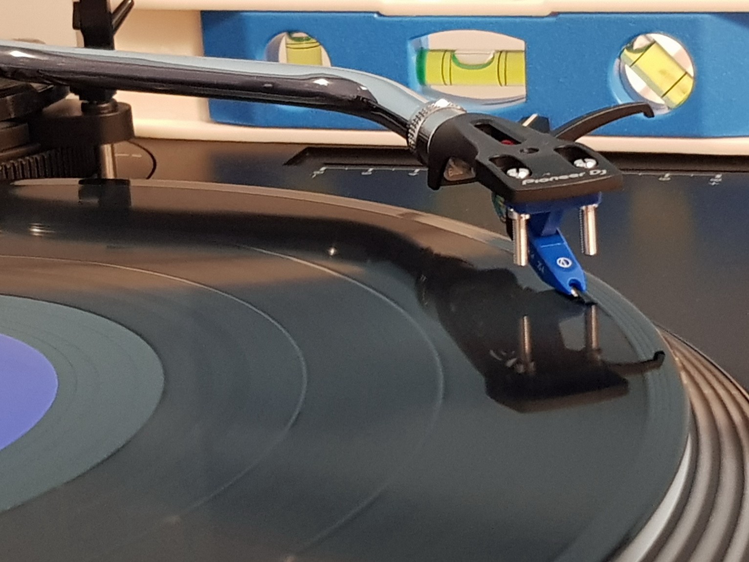
I know that it then depends not only on the electronics I've made and the cables that connect it all, but also on the phonograph needle, its characteristics and its MM/MC circuit, angles, mechanics of the rotating plate, its vibrations/speed variations, and finally with the test-phonograph plate and its condition, etc.
What I did was to let the record play live and the needle to hover 5mm above it to pick up the White-noise hum of air movement (which is almost a regular frequency distribution) to see how my preamp modification behaves and then I noticed a huge sensitivity to EMI pollution with the main voltage phase (in my case at 50Hz and 100..150Hz for LED lighting).
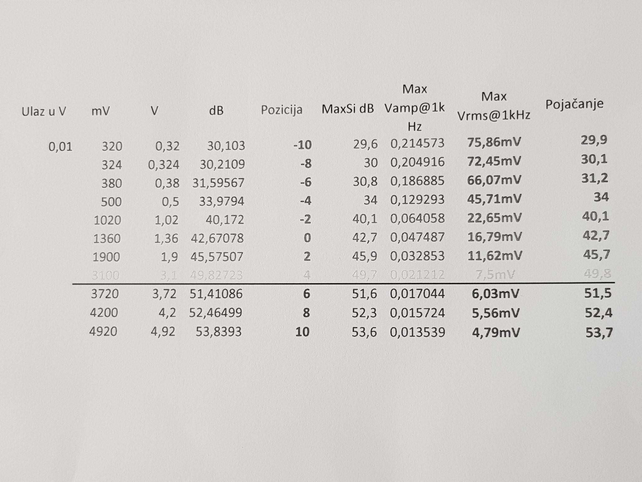
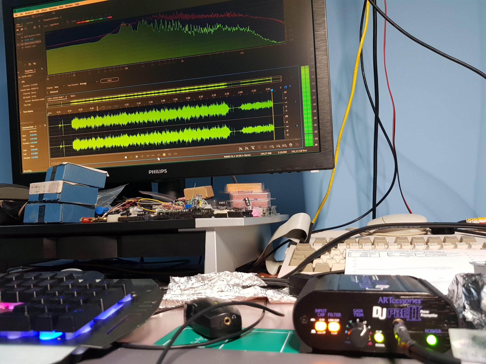
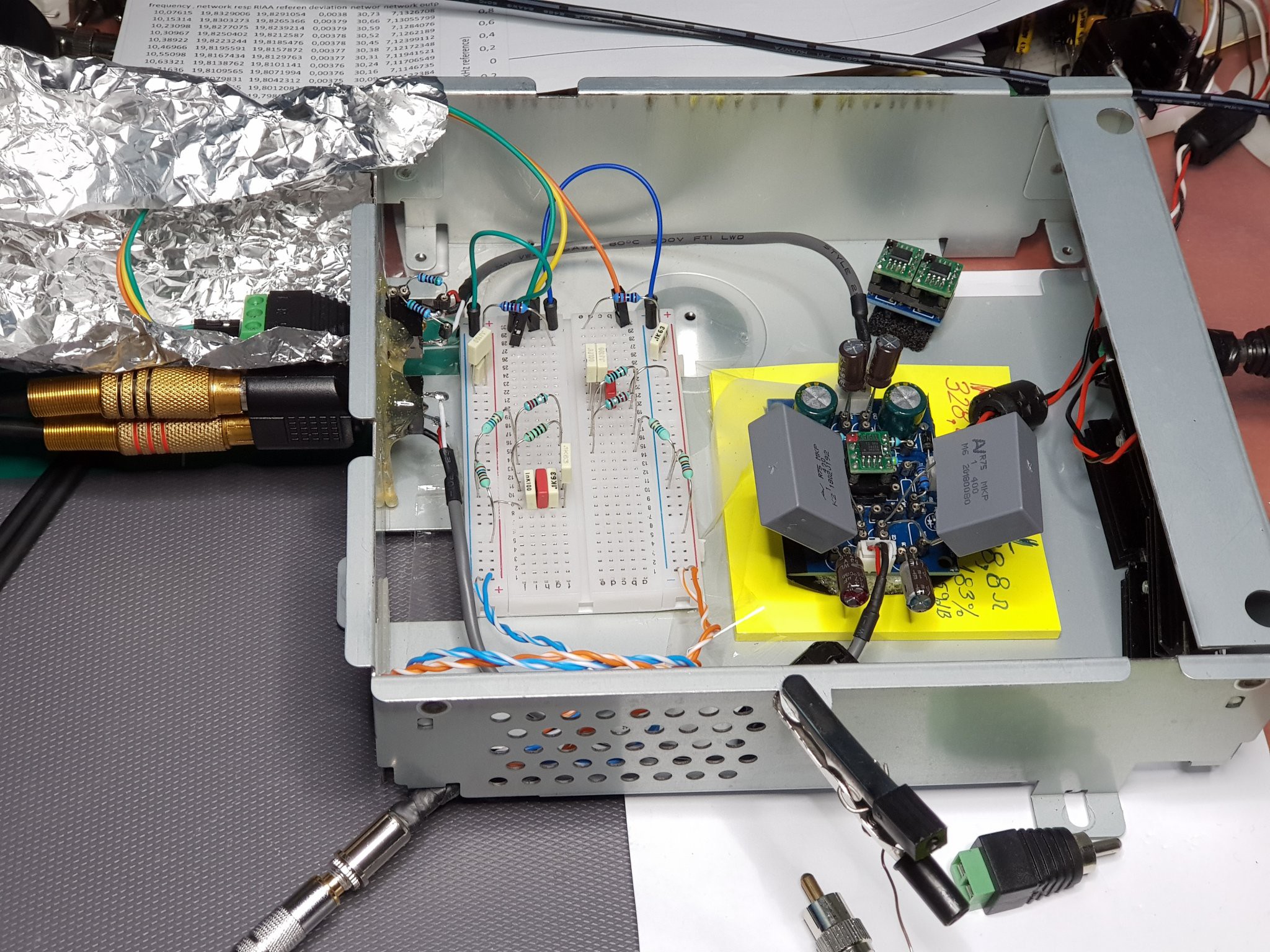
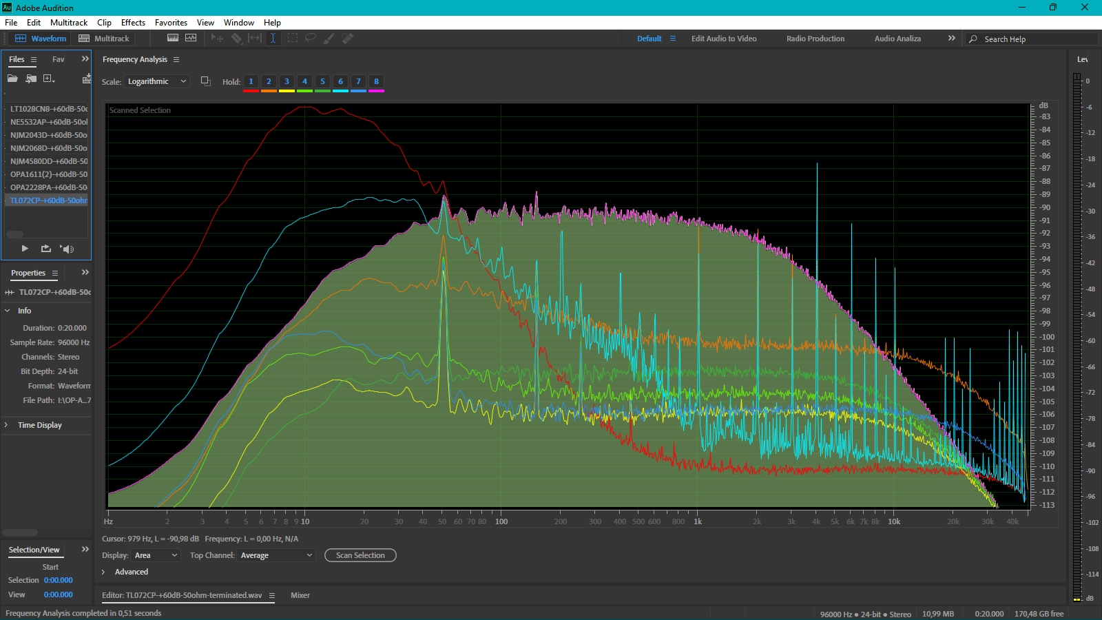
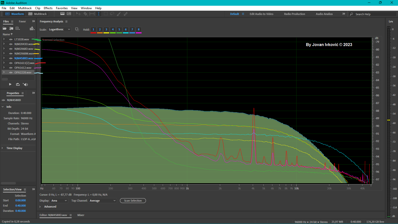
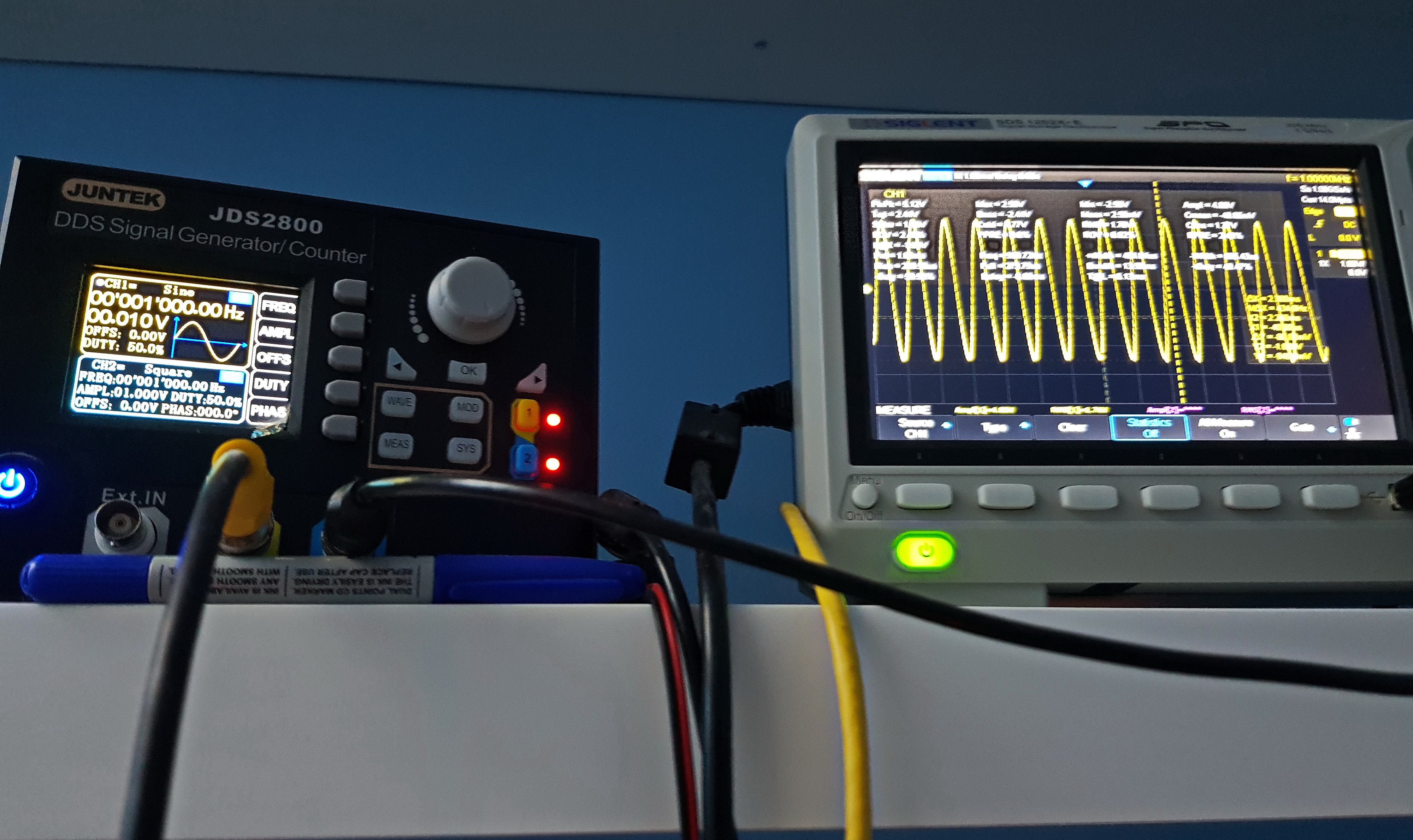
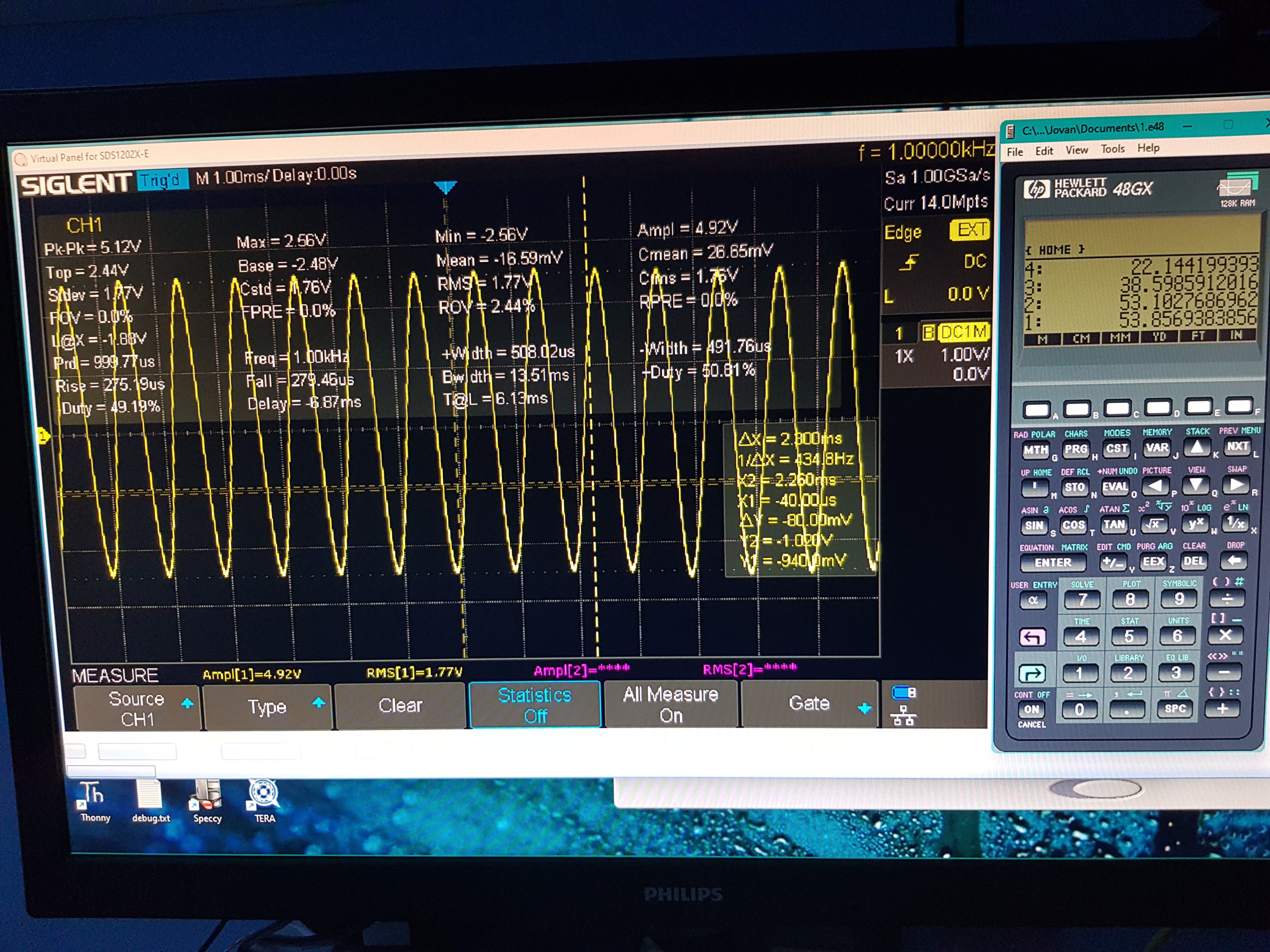
After that, I nicely recorded a linear Audio scale from 1 to 40kHz, passed it through a -40dB attenuator and then played it on the input of the Preamp, and I waited for the input on another SB card and recorded it to get a diagram afterwards that "Looks" a lot like the RIAA curve. (See attachment)
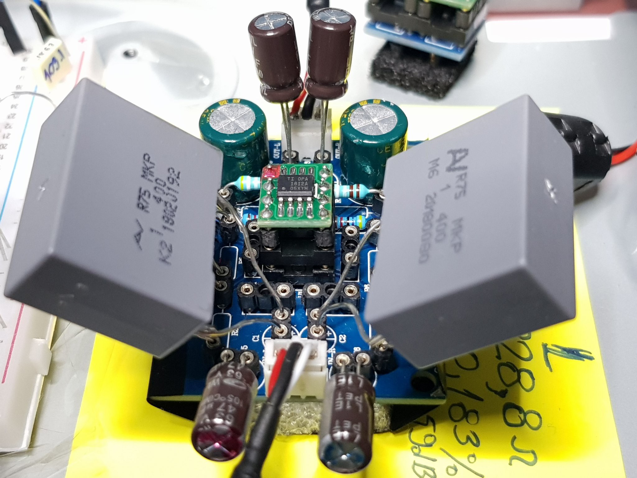
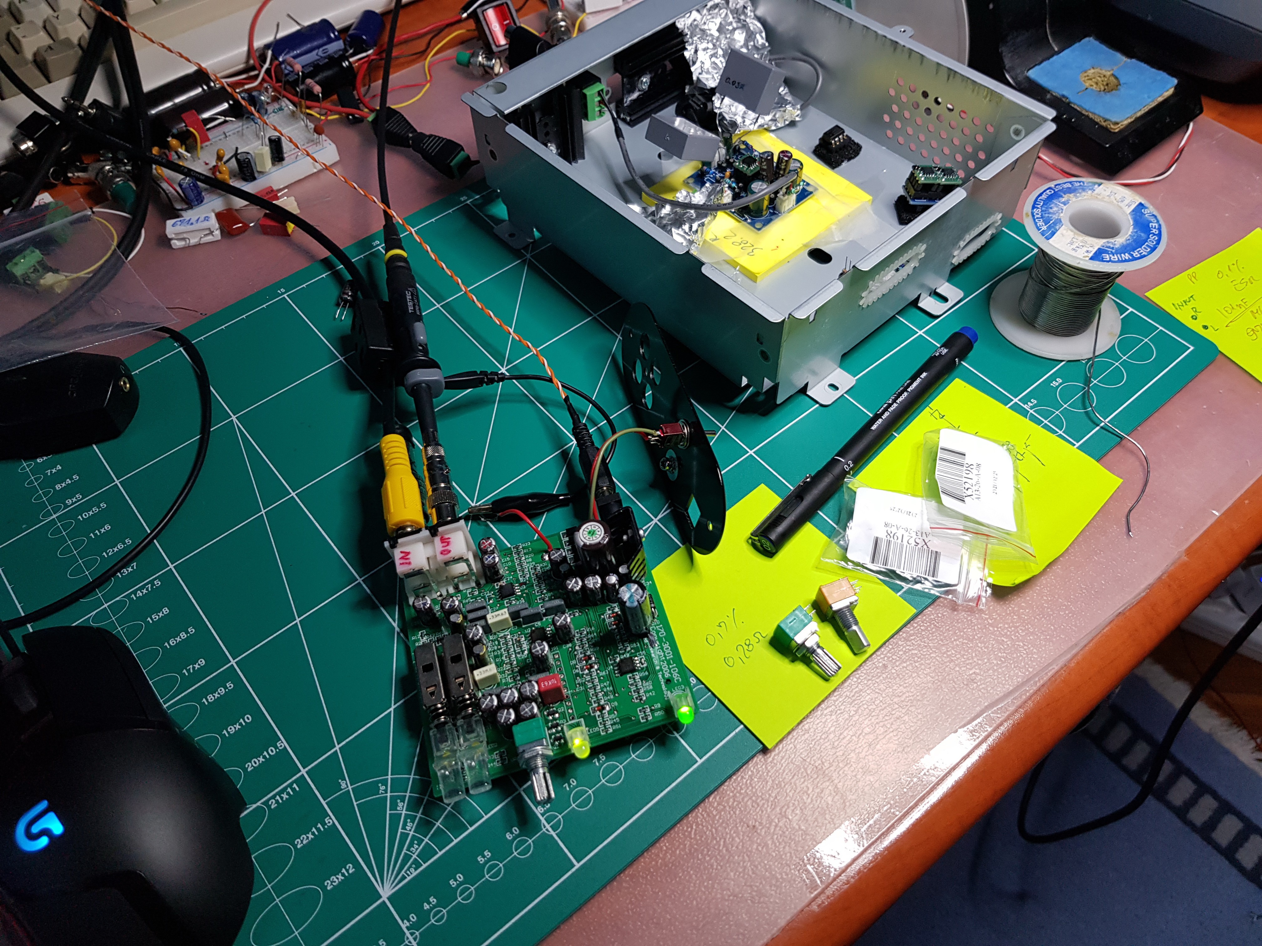
For my design, the SB was not good enough, so I also "repacked" it in a big DIY project by replacing all its key ADC and DAC -Op.Amp out components but that's a story for another project. In short, I "gilded" it wherever it was needed so that its audio input instead of NoName became Nichicon low ESR audio special, and on the Primary output, all also became Panasonic Low ESR gold. And Op.Amps instead of NJM4556A and LM4558 were replaced with OPA1612A and NJM4580D and so I won't list all the results in total -116dB or measured <0.0001% THD(12h)+N.
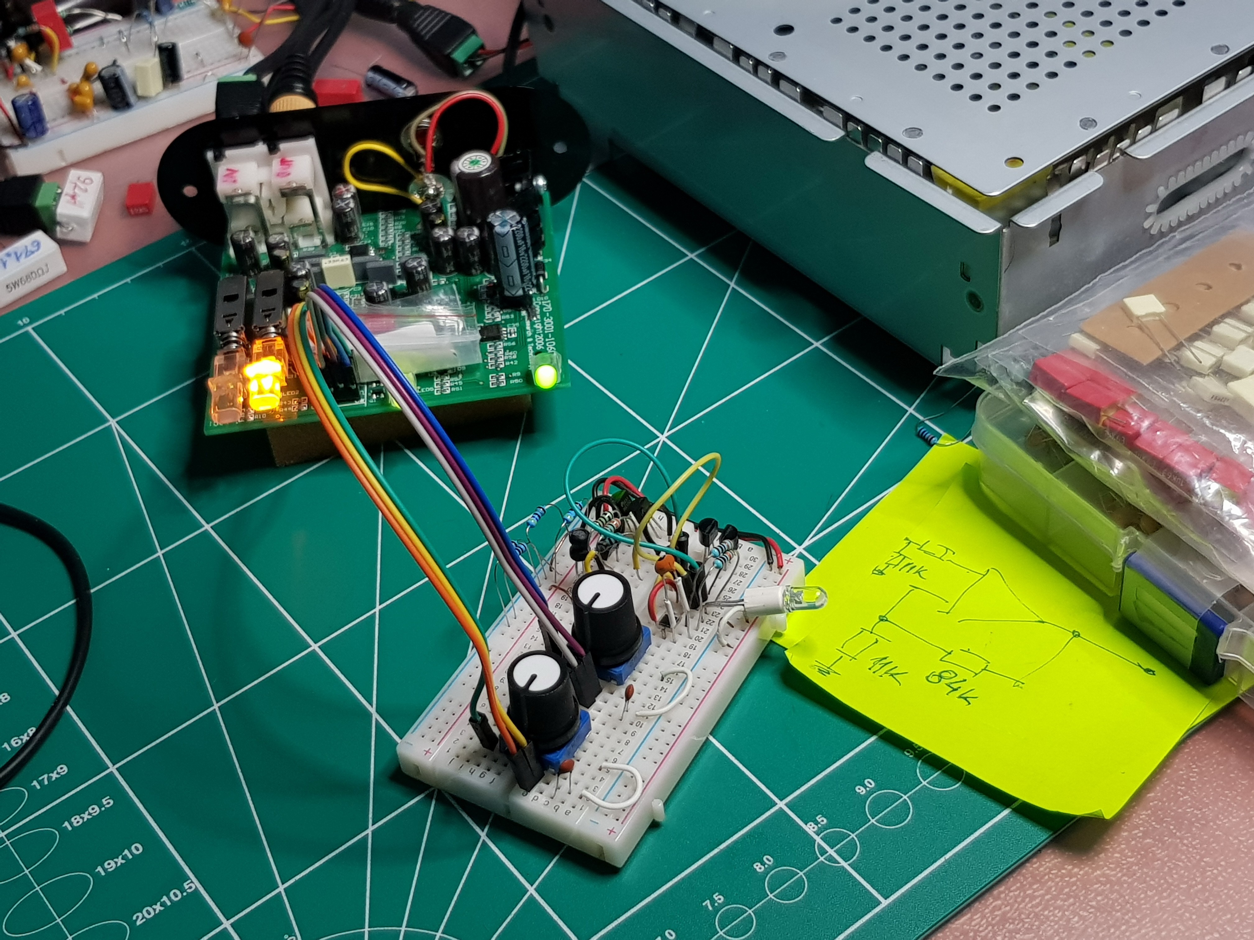
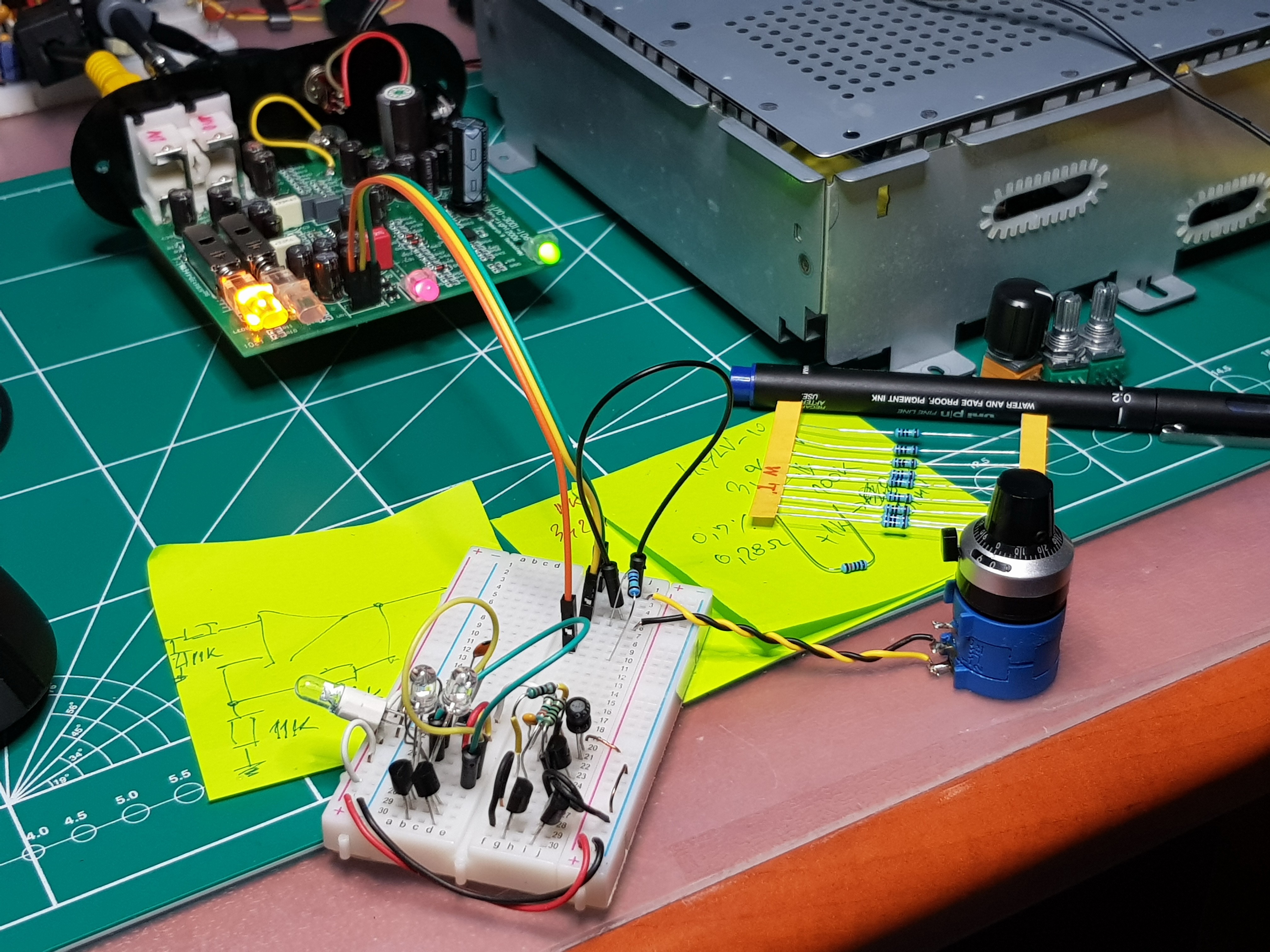
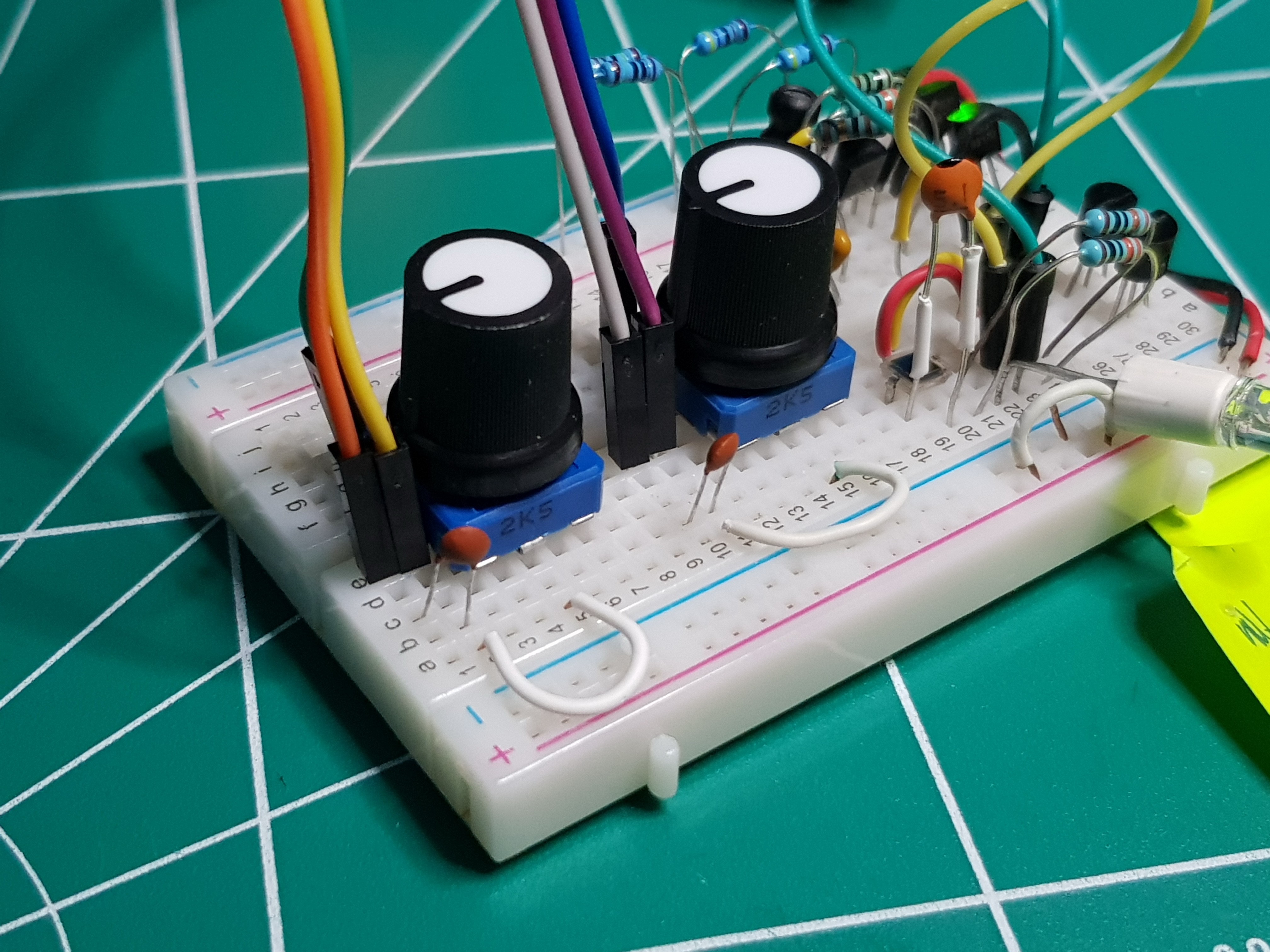
But in my opinion, that was not good enough for the input generator, because of some quantization harmonics that occur even when "ironing" 24bit or 32bit at 96k, so I made my little ultra low-distortion oscillator, so it was a special fun until I found
the best bulb for the input nonlinear element and then (unexpected choice) the choice of WIMA FKP 2 630V as the quietest capacitive element, manual selection of the most precise MF resistors (1..2/100s).
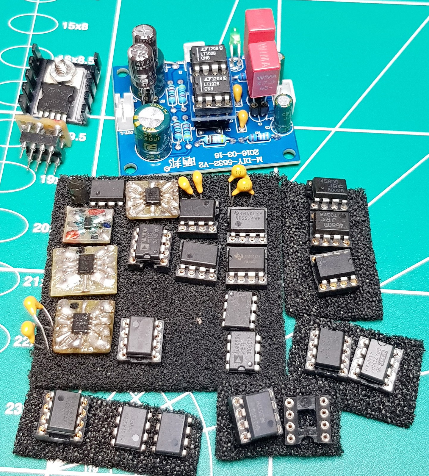
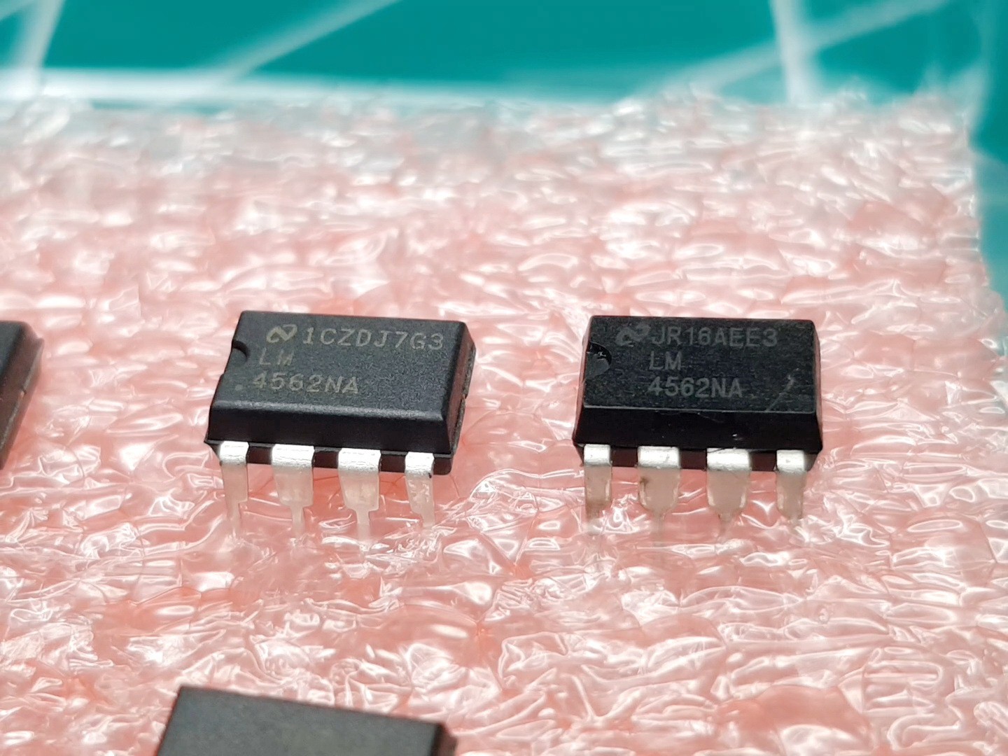
And finally, the icing on the cake, which Op. Amp produces the cleanest signal and has the lowest THD when generating -1dB (3Vpp) signal. And just when I thought that my pile of LM4562 will never serve me again (when I already have a ton of OPA16xxx, NJM8xxx,LT...) when, lo and behold, it is by far the BEST choice for this.
In any case, I am still working on the development of test equipment so that my theoretical and protoboard system can be reliably declared to be 0.01dB compliant with RIAA. For now, it's just based on listening to SB_1(Out) -> Auten(-40dB) -> My_Pream ->SB_2(Input)->FFT65k.
More about all of the above in some new projects.
Thank you for your interest, Isaac.
Best regards,
Dr. Jovan Ivković
Look for:
Comparation sound resolution of NJM2068DD vs OPA1612(MOD2) or Bultin PLX500 PreAmp.png
Comparation RIAA_40dB-MOD(FOM65k)Passive-PostAmp24dB vs DJPre-II MOD.png
ART-DJPREII-MOD2-Separation point from RIAA MOD1(FOM32K) and MOD(FOM65k) with 40dB(OPA1612)PreAmp.png