Current status (12/01/2019):
-->Project is COMPLETE!
-->All hardware and final enclosures are complete.
-->Reliability has been established (it doesn't burn the house down).
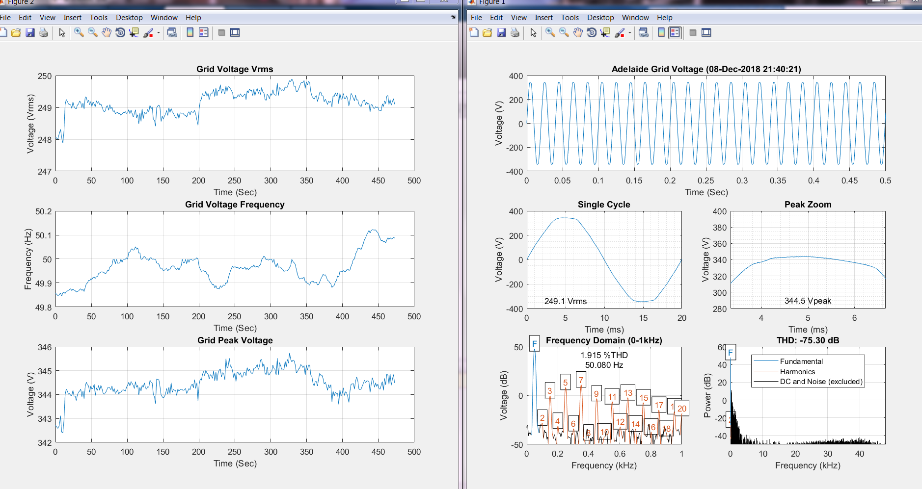
-->MATLAB code is done and generates figures correctly.
The Grid-2-Audio module is comprised of three main parts (plus an extra forth):
1. The case and IEC all-in-one power entry connector - As part of teaching myself AutoDesk Inventor, I decided to start with the mechanical aspect of the project. The presence of mains voltage potential is no joke and the design of the case reflects that. The utilisation of an IEC power socket with built in switching, fusing and illumination minimises any mains wiring around the internal space of the unit.
2. The PCB power supply and mains input - As the unit is design to measure the grid voltage and introduce minimal noise, the power supply needs to ideally draw a minimal sinusoidal current (at the fundamental frequency) in phase with the voltage. Additionally, there needs to be isolation between the mains measurement circuit and the output side, forcing the requirement of multiple transformer taps for the whole PCB.
3. The PCB signal conditioning - The mains signal needs to be conditioned to the 3.5mm audio format and protected from shorts. As an extra feature, a 50Hz high-pass filter will be included to provide an alternate "harmonic only" output to increase the dynamic range for harmonic analysis. EDIT - The filter has since been removed and will now be accomplished via software libraries within MATLAB, etc.
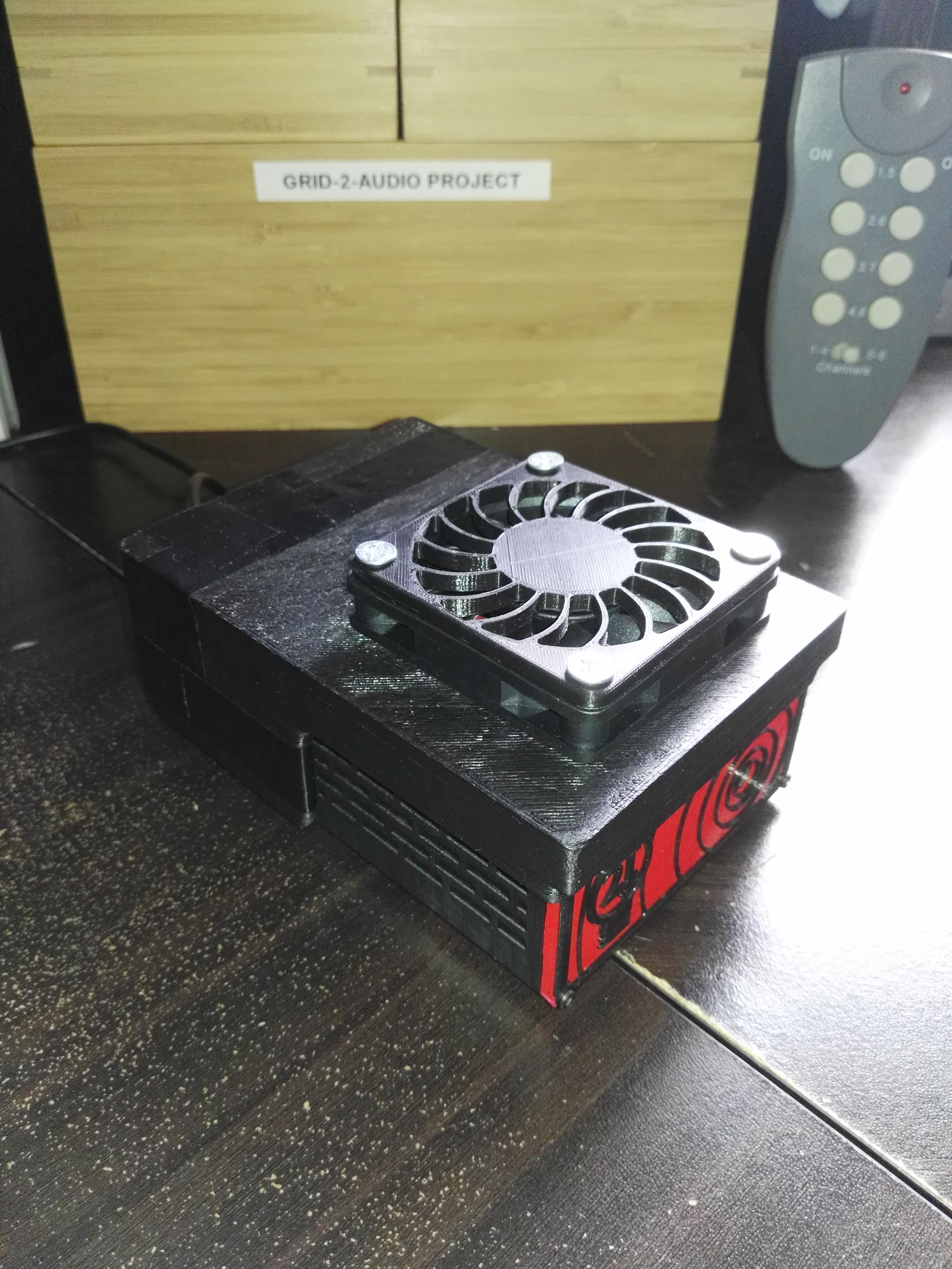
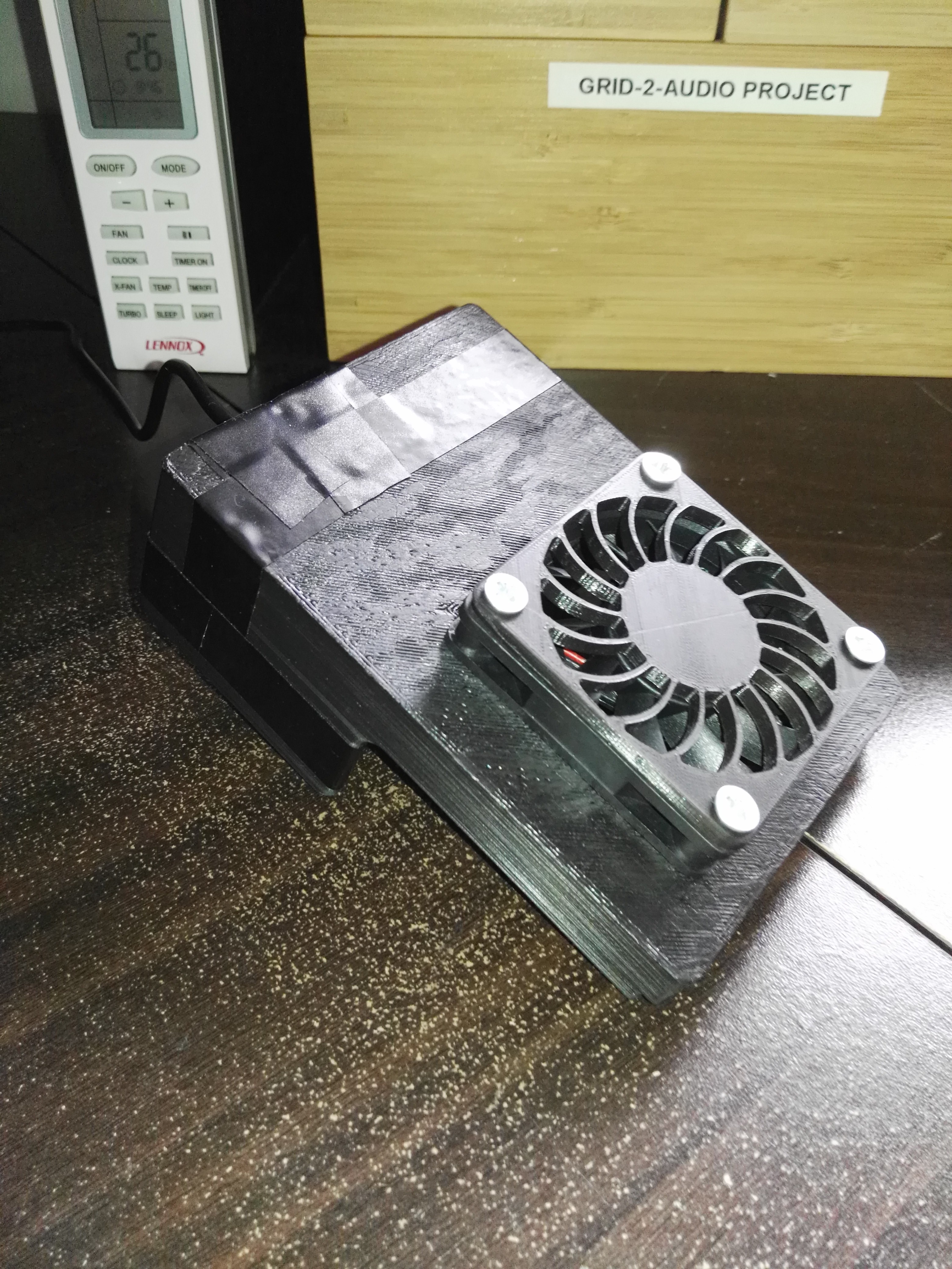
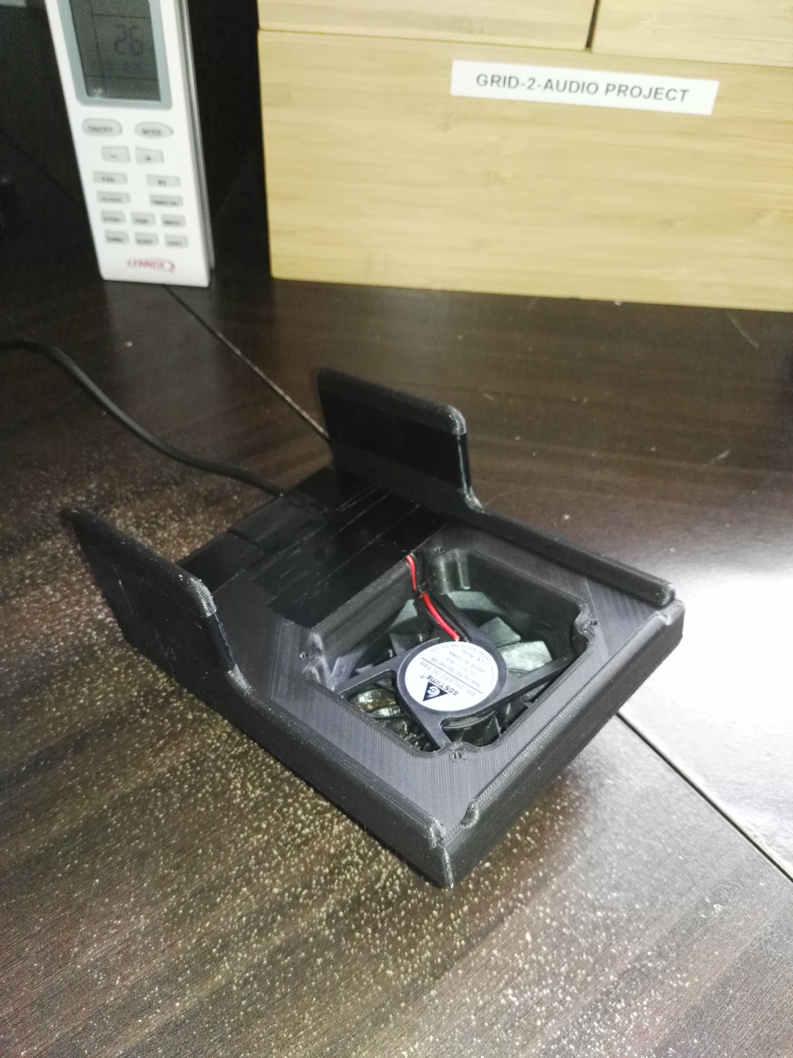
4. Cooling fan add-on! Let's not start fires here.
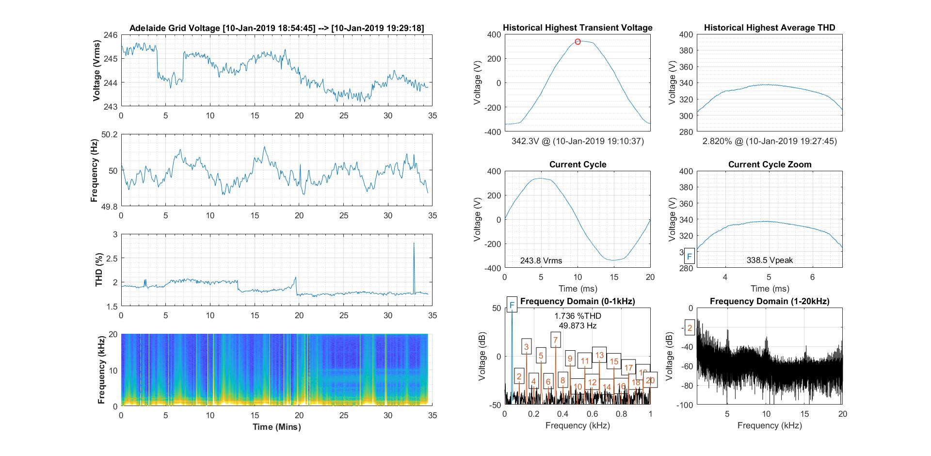
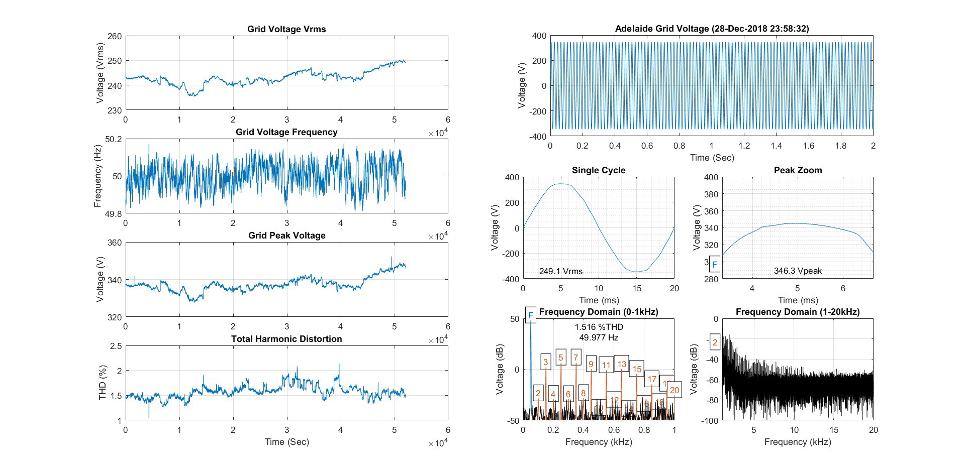
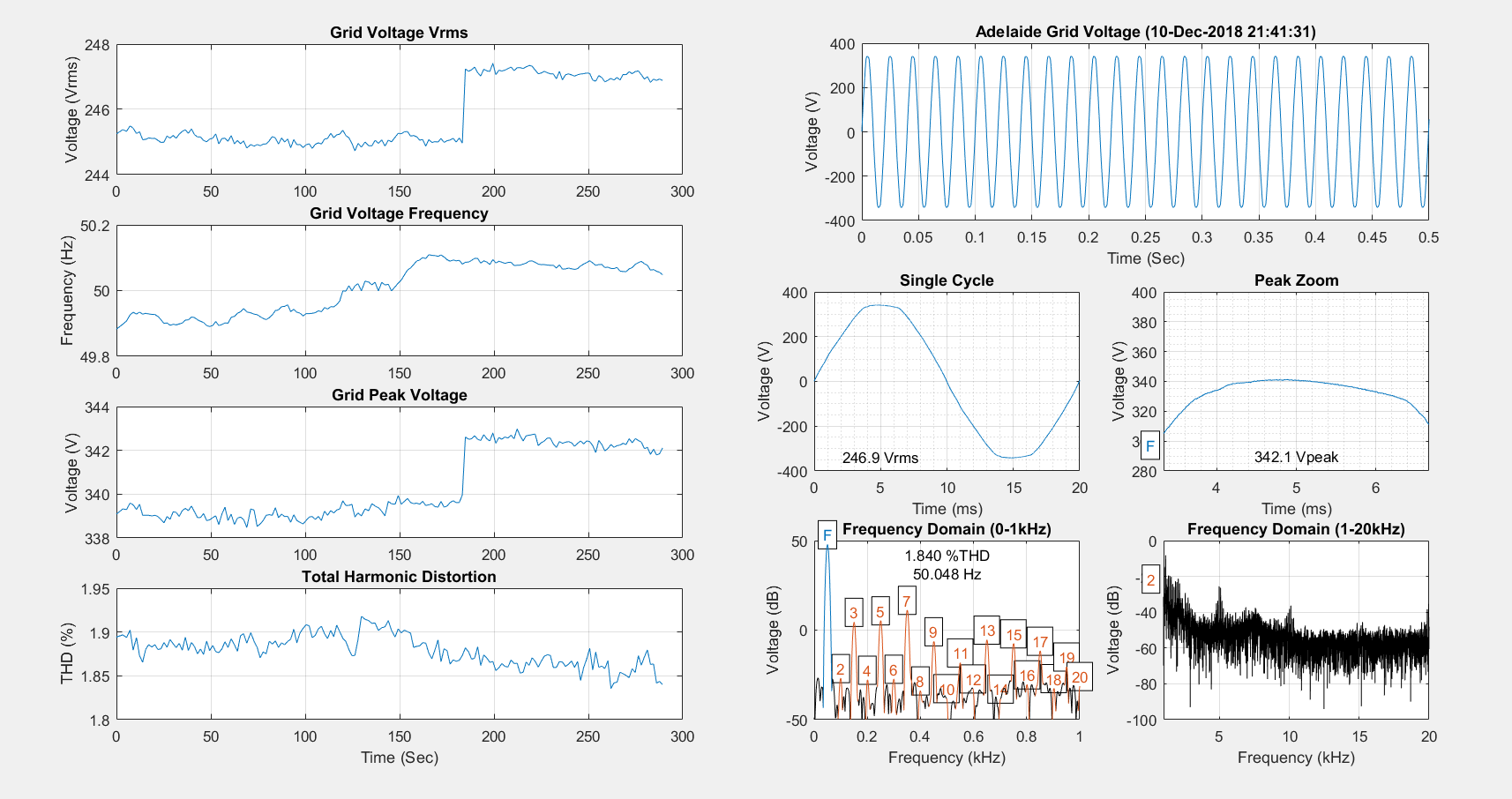
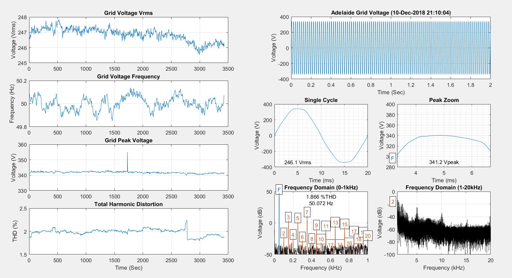
Here's some pictures of the project and my favourite results:
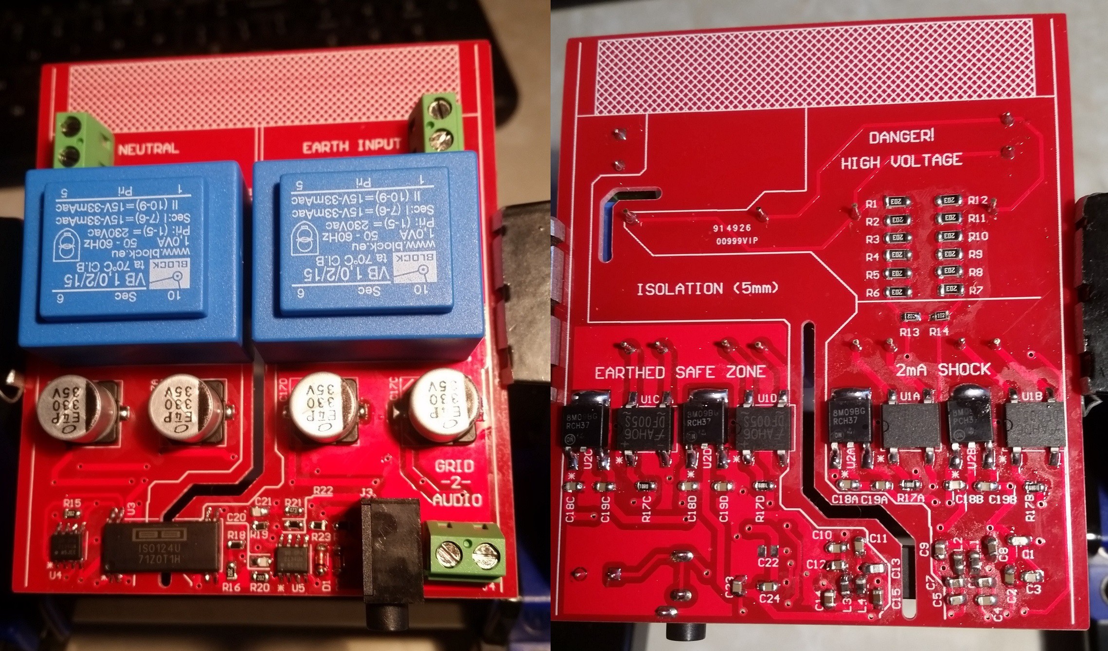
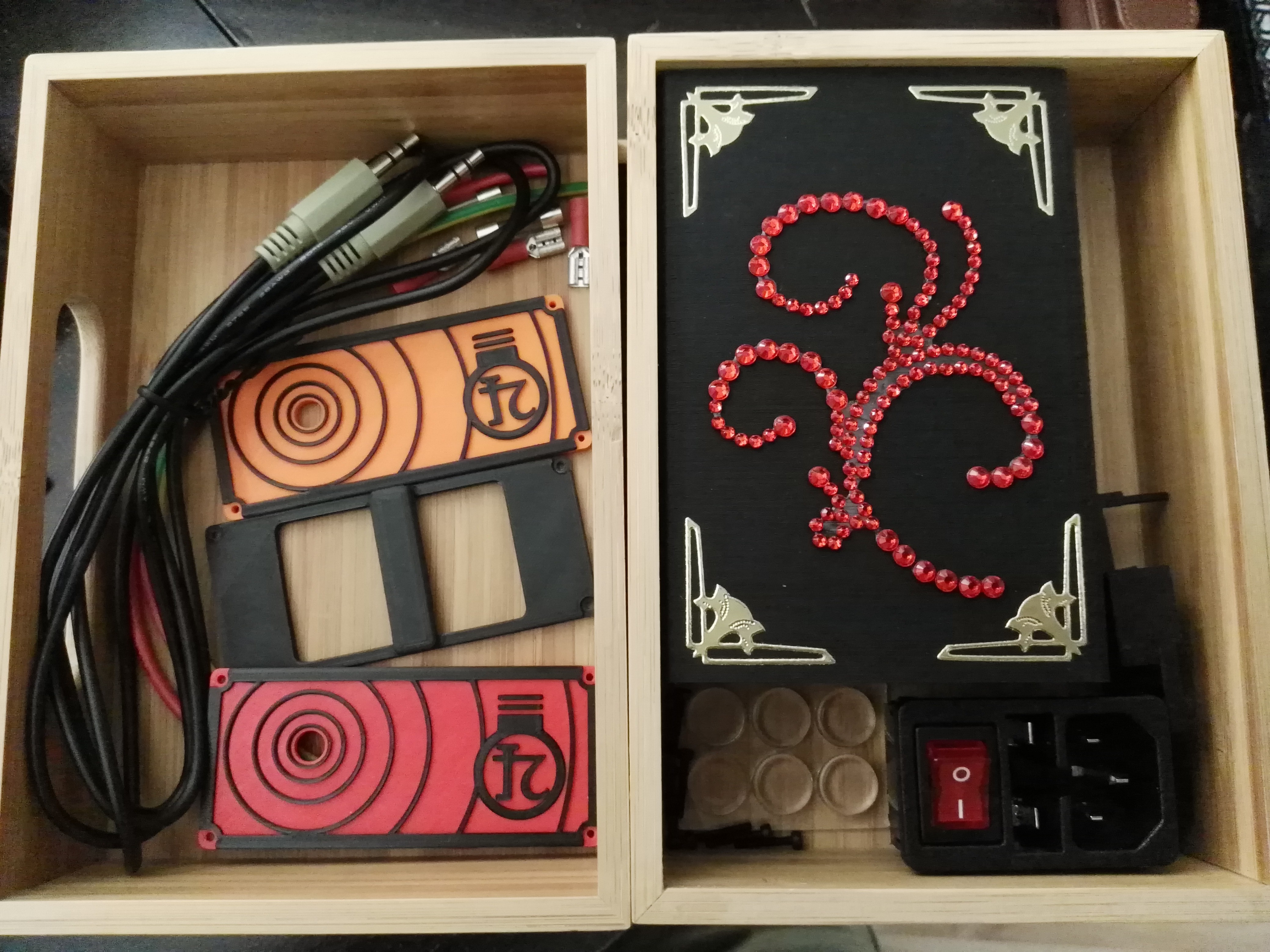
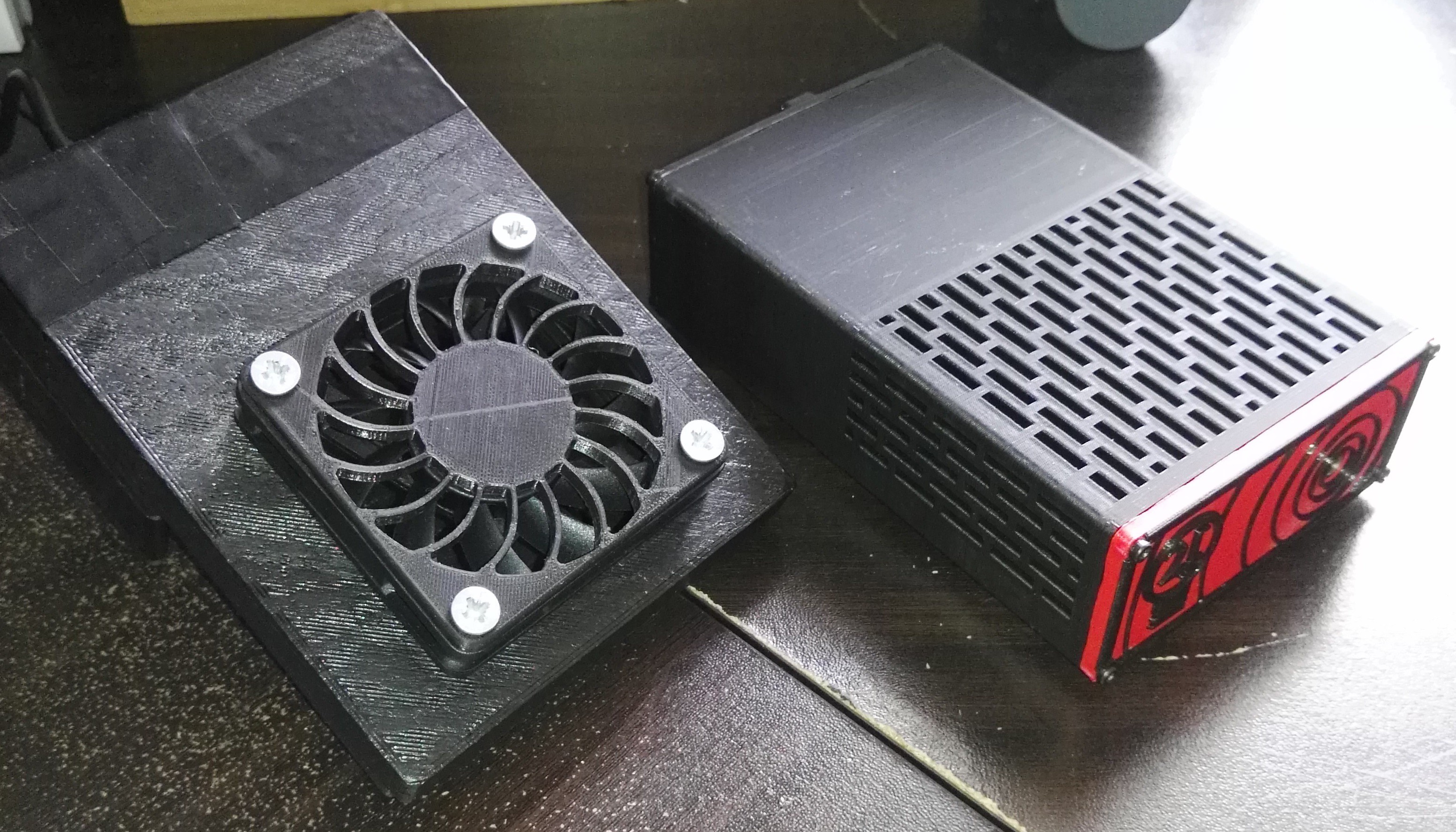
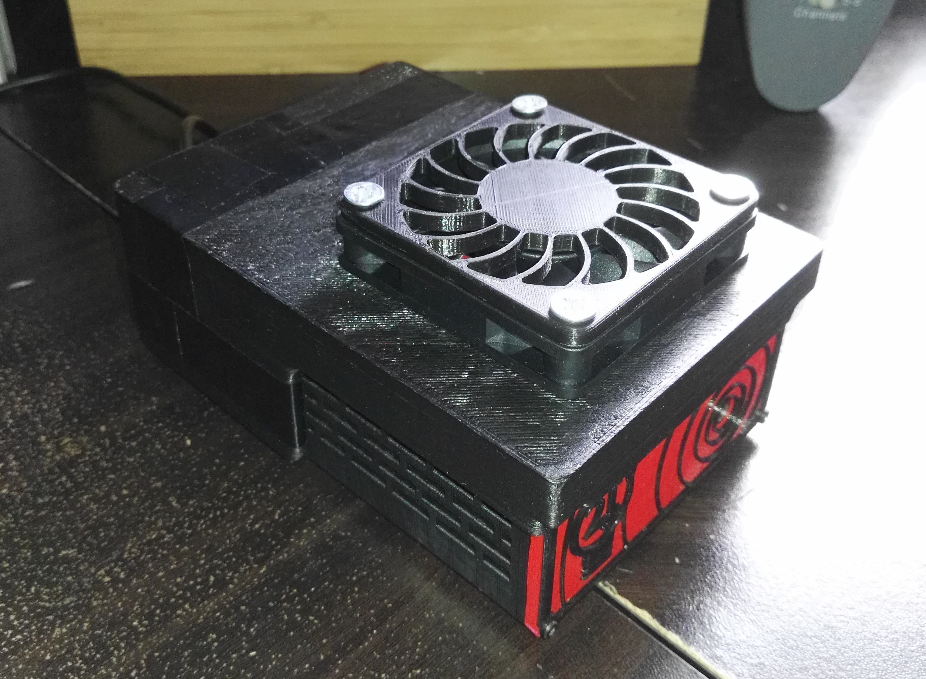
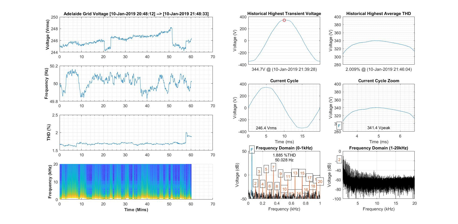
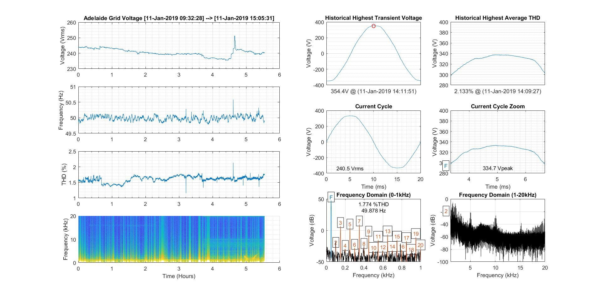
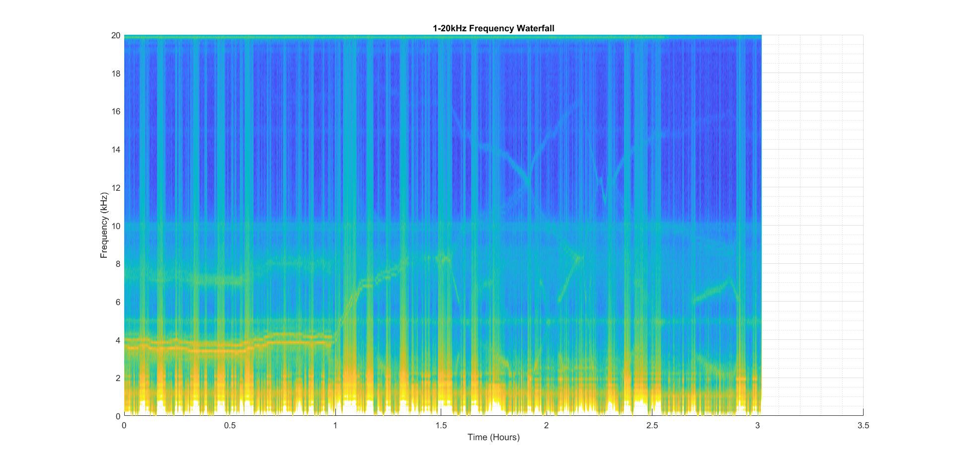
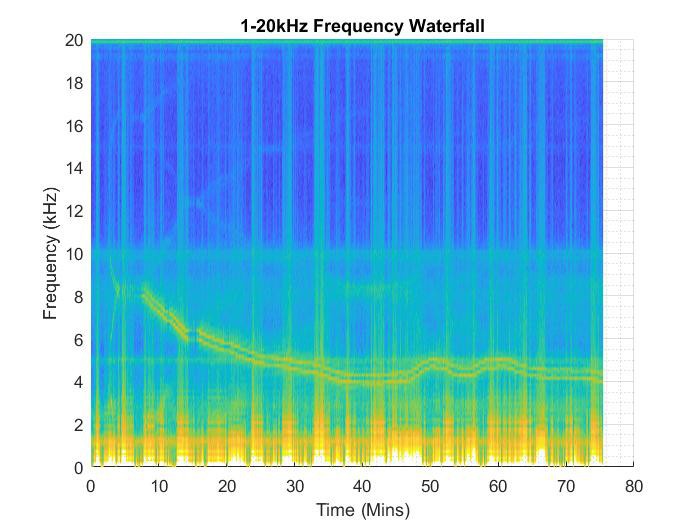
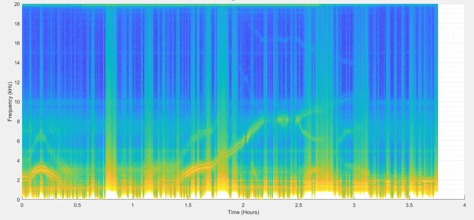
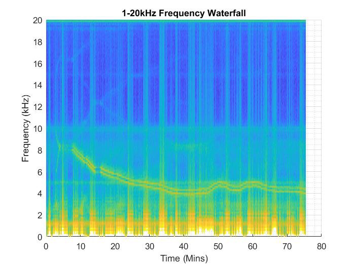
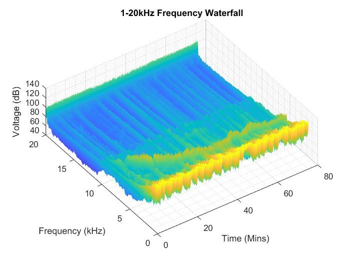
Now the good stuff! The waterfall spectrums captured while some interesting equipment was in operation:
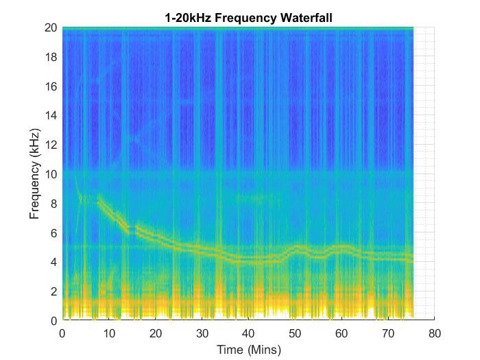
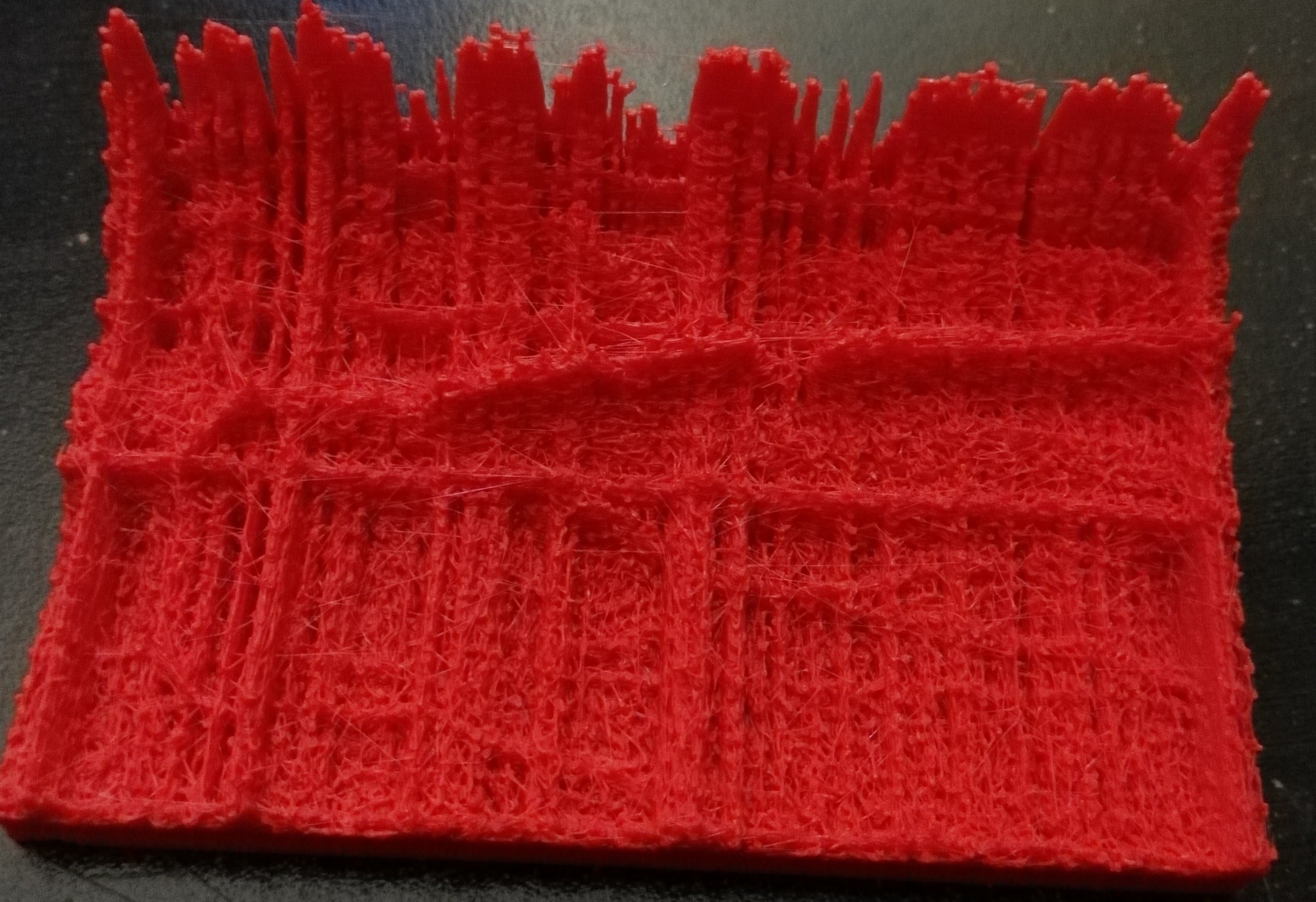
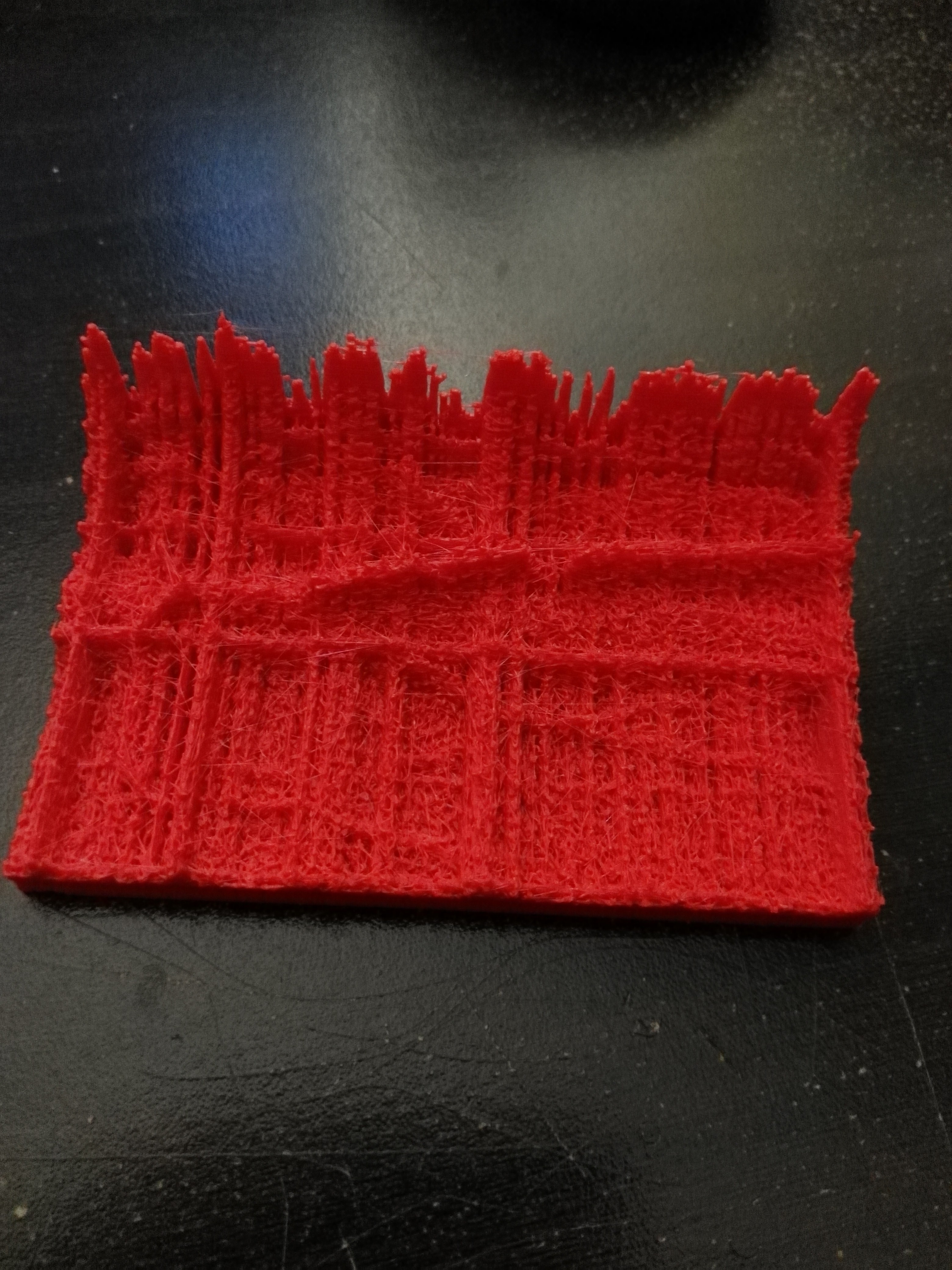
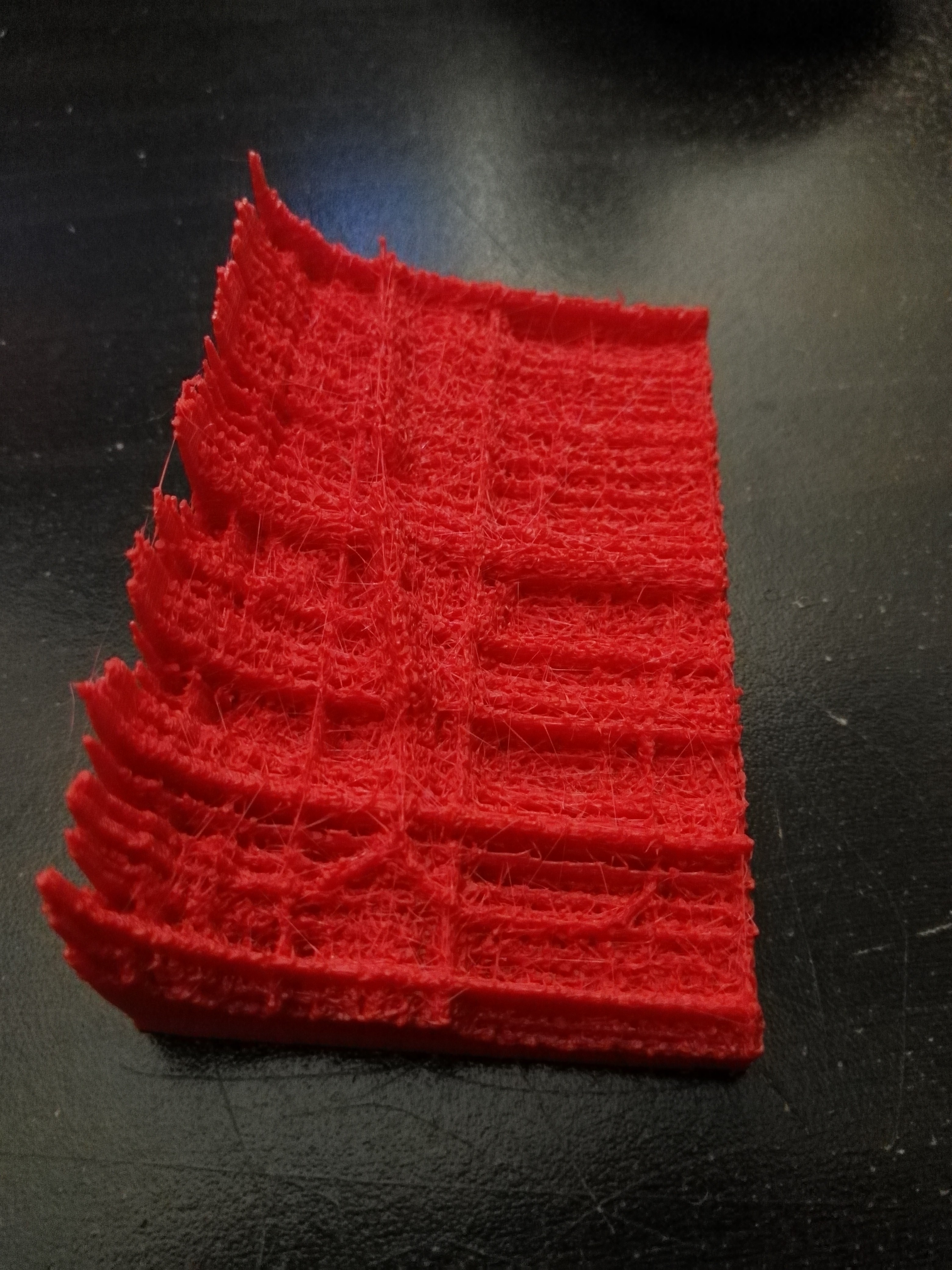
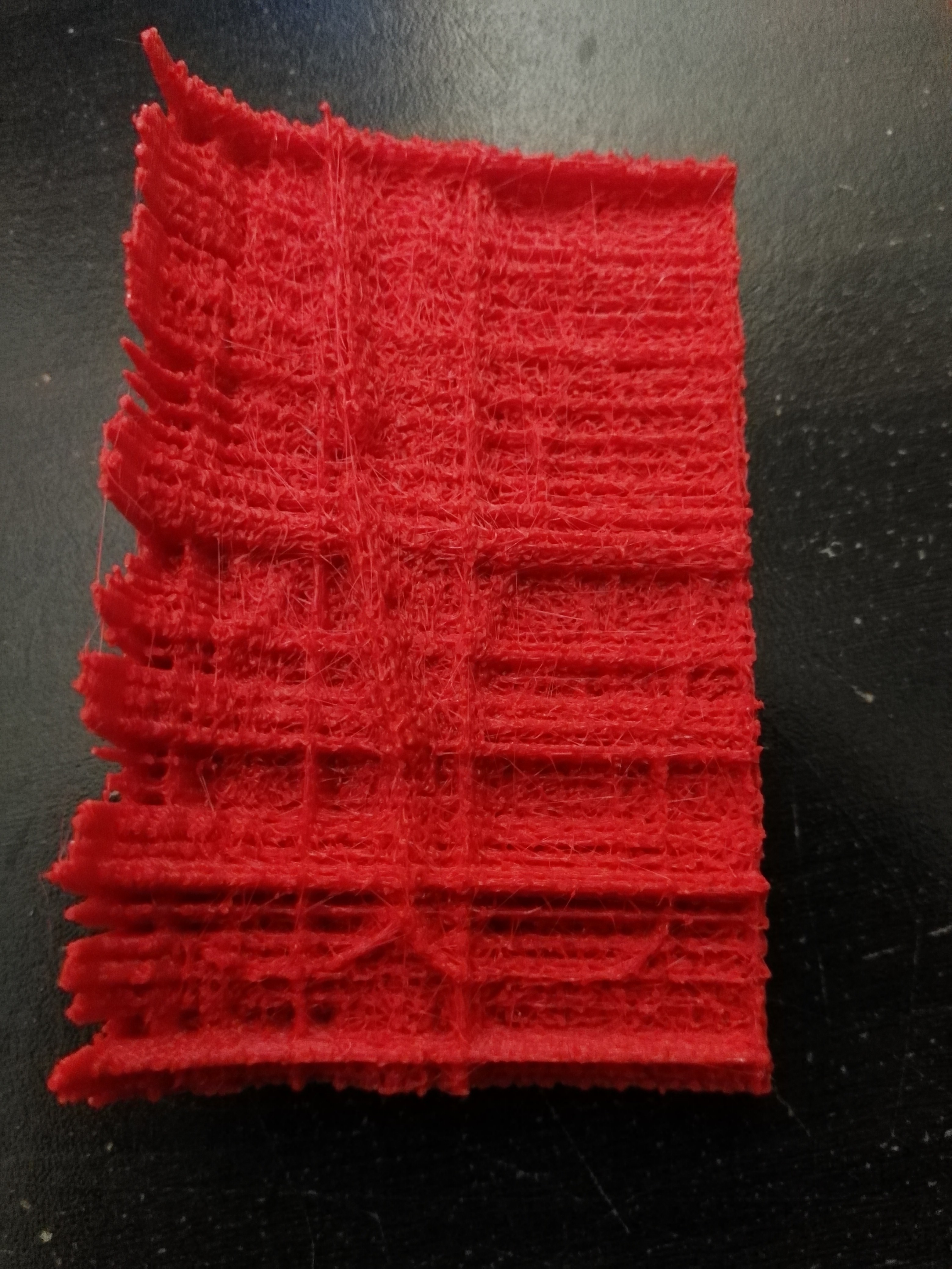
(Bonus vertically-mirrored 3D print of the first 40 minutes above):
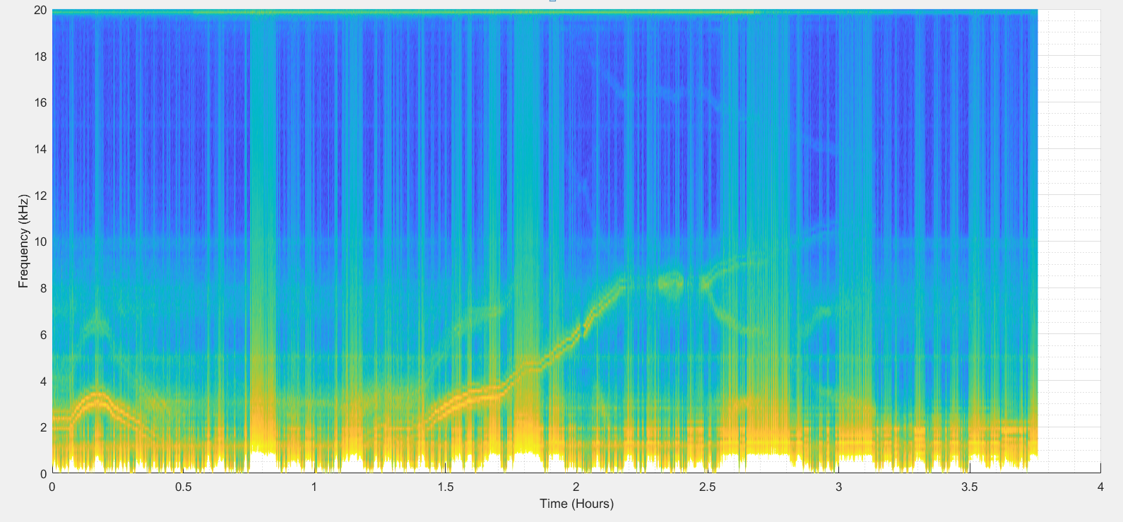
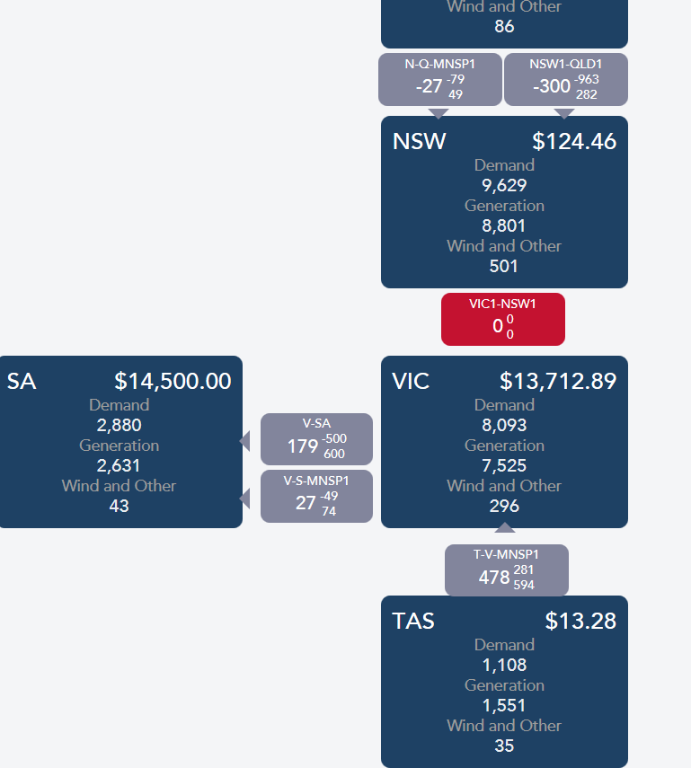
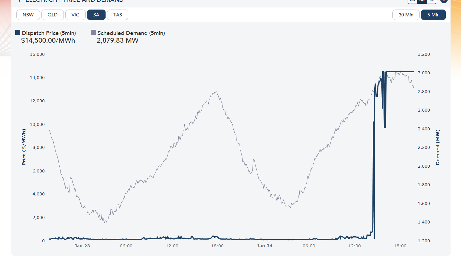
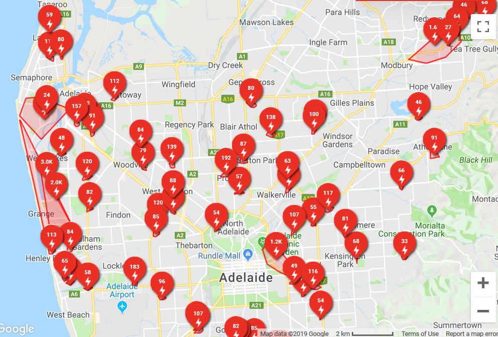
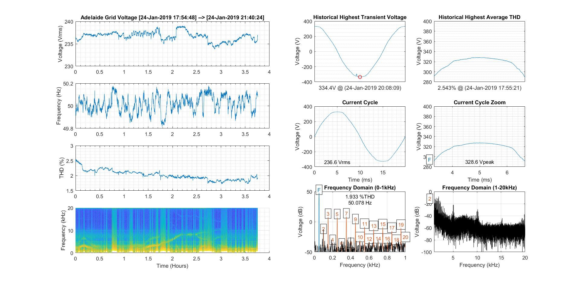
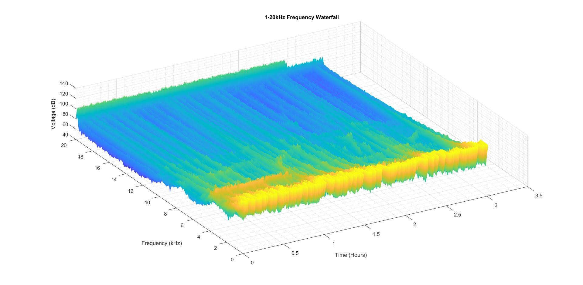
 This third one is from 6.00pm-9.40pm of the hottest day EVER in Adelaide, Australia (24/01/19):
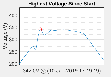
A good transient captured (unrelated to above):
 The process of capturing some data:
And finally, what does the grid "sound" like (with a high pass filter)?
Note:
Brian was kind enough to write about this project on the main page some time back: https://hackaday.com/2018/08/23/listening-to-mains-power/
There were some interesting ideas in the comments about retrieving isolated signals, but what I certainly took to heart was the emphasis on isolation distances. Although I couldn't achieve 6mm clearance (I increased it to 5mm), I added slots (for extra creepage) and increased the mains voltage divider resistance values to only allow a "2mA shock" if the isolation AND earth fail.
Edit:
Part 2: https://hackaday.com/2019/01/14/listening-to-mains-power-part-2/
 David Scholten






 Matt Bradshaw
 Pepijn de Vos
 jaromir.sukuba
No updates recently, I know, but some progress is being made.
MATLAB is proving easier to use than I remember (I finally updated to the latest version) and plotting is ridiculously easy.