0%
0%
Flounder Z180 Computer
Standalone single-board computer based on the Zilog Z180 CPU
 Colin Maykish
Become a Hackaday.io member
Already have an account? Log in.
Just one more thing
To make the experience fit your profile, pick a username and tell us what interests you.
Pick an awesome username
hackaday.io/
Your profile's URL: hackaday.io/username. Max 25 alphanumeric characters.
Pick a few interests
Projects that share your interests
People that share your interests
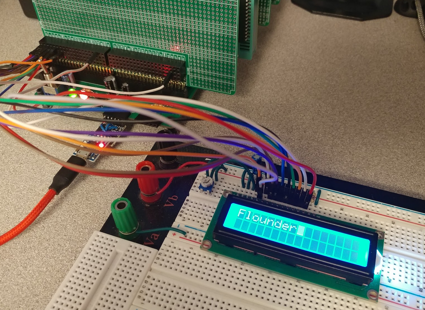
 Overall, I couldn't be happier with the first revision of this PCB. There are a few minor tweaks to make for the next iteration, but there's no rush on that. I have feature parity with my prototype and nothing is blocking me from spending some time on the software side to get Flounder doing something fun. I've only got a few more days in the Retro Challenge and I'd like to have a cool demo to show off instead of just a serial monitor program.
 There are no obvious manufacturing issues or design problems that I can see, so it's time to start building. First step is the regulator circuit. It's a simple LM2576 buck converter stepping the 12v input down to 5v.
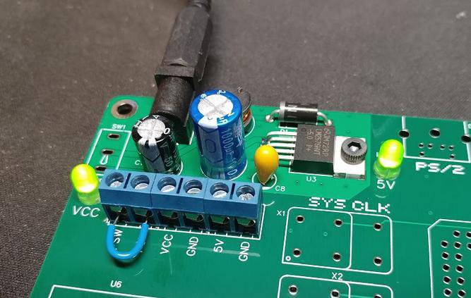 Nothing blew up and the LEDs come on. Multi-meter shows a solid 5v on the output. Good start.
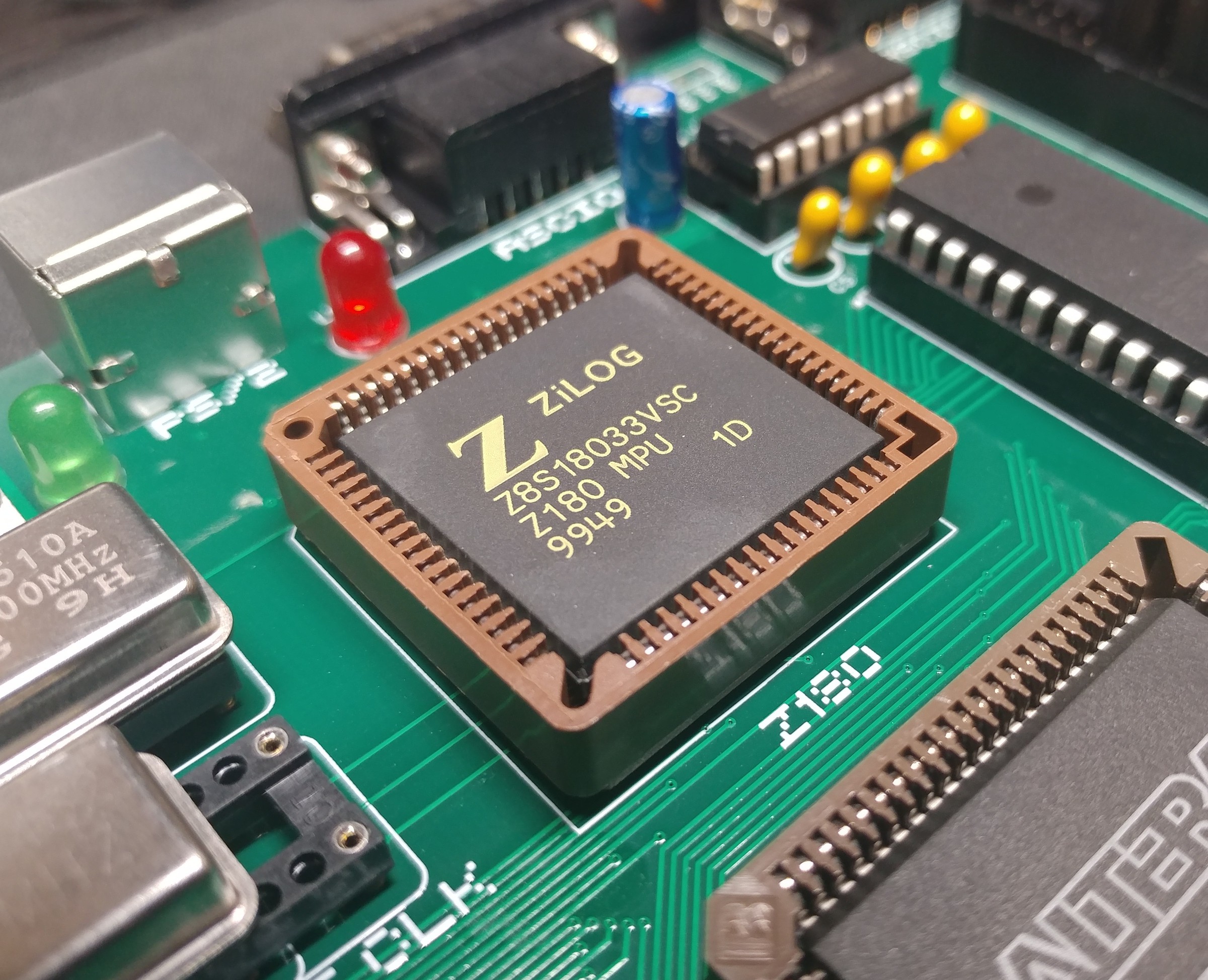
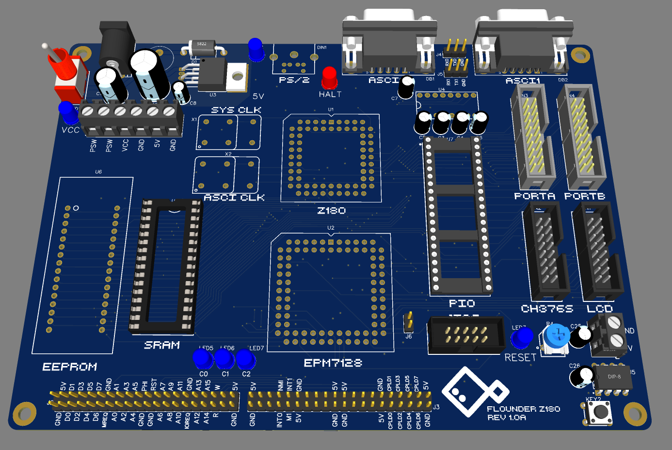
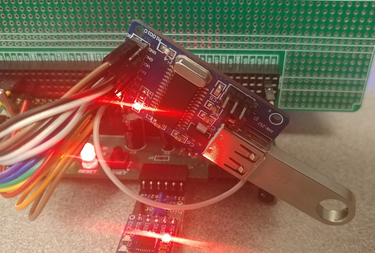
 In the first Flounder prototype, I used the 44-pin version of the EPM7064 CPLD, but on this PCB, I opted for the 84-pin package. I was a little nervous I missed something obvious in the transition, but happily, that was not the the case. The CPLD has two clock inputs: the PHI output from the Z180 and a second oscillator directly connected. Since the Z180 is not yet installed, I soldered in the secondary oscillator and the CPLD along with its debug LEDs and programming header.
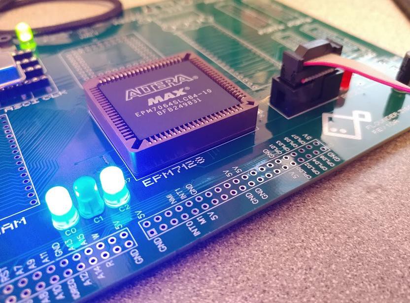 Quartus detected the CPLD right away and I was able to program a simple counter/blinker circuit to test the clock input and LEDs. The CPLD is alive!
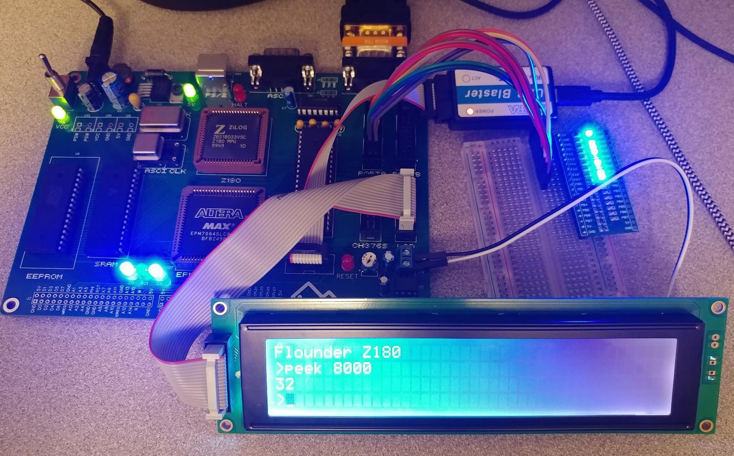
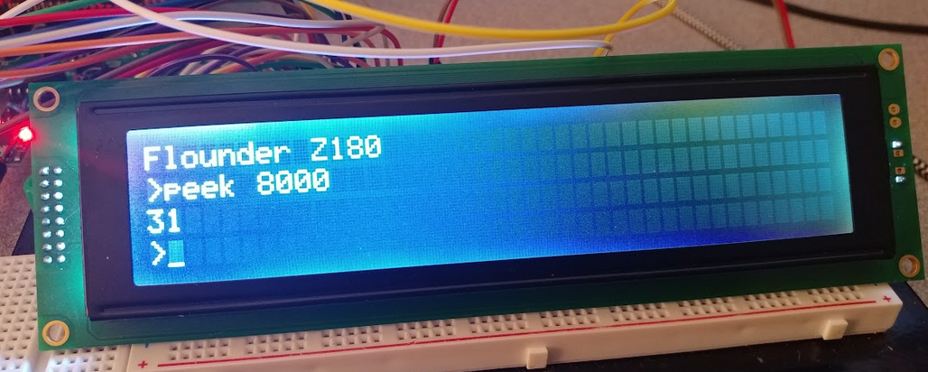
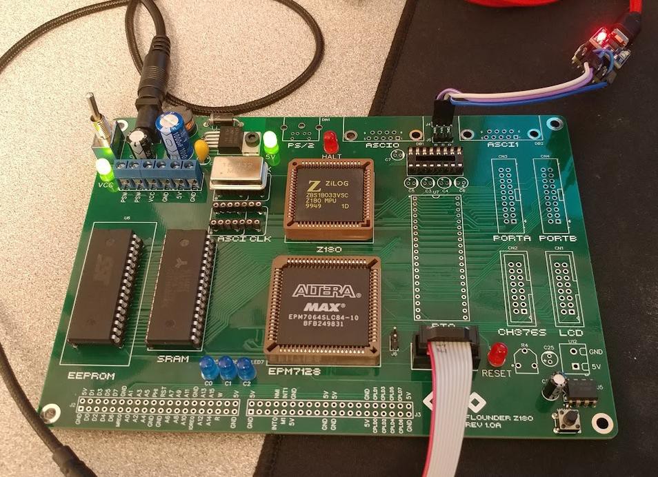 The serial monitor is running! Very nice. With the CPU, memory, and serial port working, everything else feels like a bonus.
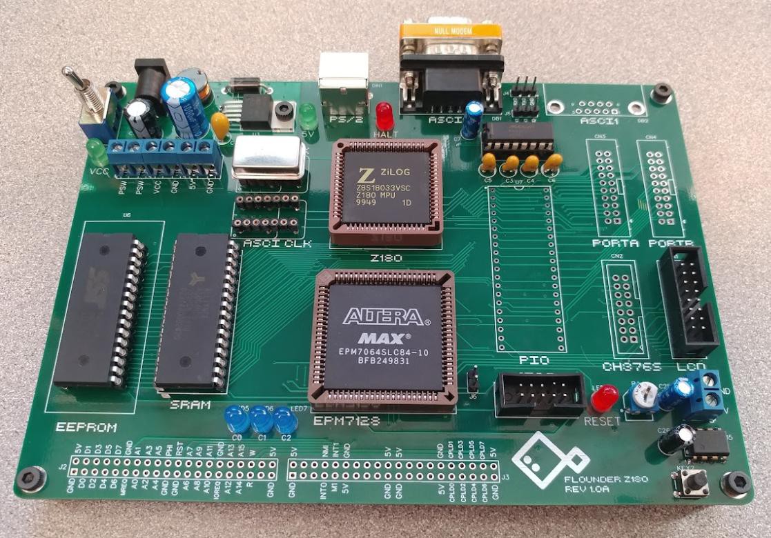
 Ross Bamford
 James Ots
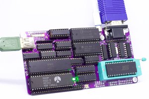
 Anders Nielsen
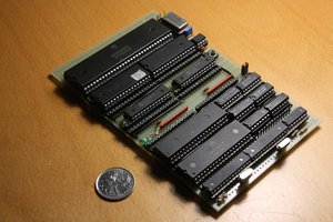
 Hayden Kroepfl