 diysciborg
Educational
In addition to build plans, I will attempt to write basic outlines for in class exploration and guided content learning. The educational goal is to connect industrial arts, engineering and science. In this regard, guided explorations will encourage students to brainstorm and attempt to build various weather related devices while studying content material related to the parameter being explored.
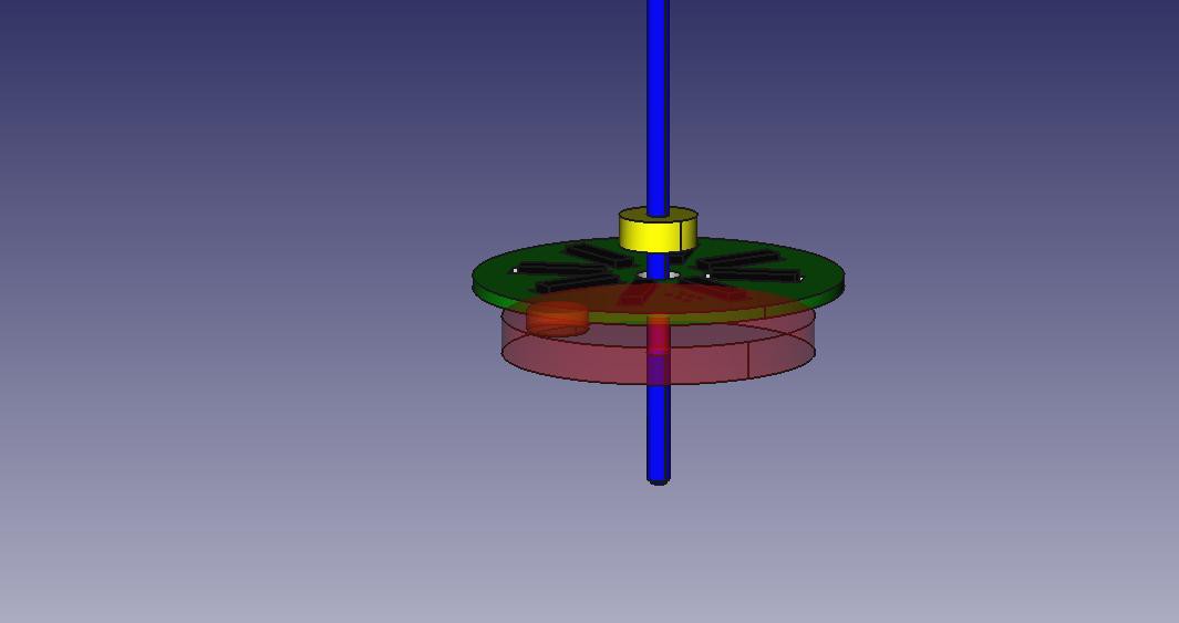
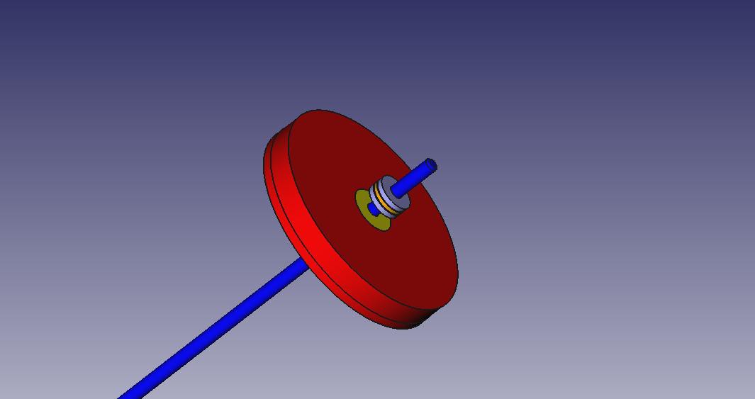
As an example, let's say we are studying wind speed. We might ask students to first brainstorm ways in which they might measure it. Many of the more clever students will immediately imagine something similar to an anemometer.
We next ask them to research different ways to measure wind, such as pressure and force. At this stage, we should brainstorm objects in every day life that reflect the effects of wind, and how we might indirectly measure it.
The first scientist to begin meaningful measurements of wind force was inspired by the hanging signboards outside of ins, bars and shops. By first weighing the signboard and then applying an angle gauge to it, he was able to determine the amount of force the wind exerts on the board when it swings to any angle on the gauge.
We next attempt to replicate such an experiment while applying micro-controllers (Arduino) to the task of measuring the angle. This could be with a potentiometer, encoder, or optical sensor.
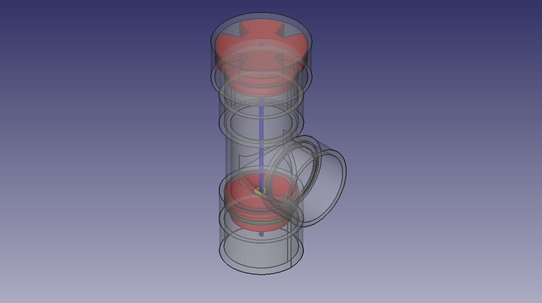
Why PVC Piping?
- Metric PVC-U is available in every country (including the USA). I have yet to confirm this, but I suspect the dimensions are at least approximately accurate from various manufacturers. Thus all of my parts *SHOULD* work in your country... sanding may be required :<
- PVC-U is UV stabilized, and can be exposed to sunlight for decades without any painted overcoat before starting to break down. So, the body of the hardware at least should last for years.
- All other mechanical/metal parts are easily sourced, either from local suppliers, hobby shops, or ordered online. Parts are stainless, galvanized, aluminum, or painted (in the case of non UV stabilized plastic, such as cups of the anemometer). PCBs should be coated with conformal coating, and all areas with electronics will have desiccant silica packets.
- Acrylic laser cut parts are small enough / cheap enough to be sent in a mailing envelope as a kit. Once the concept is understood, parts could be made in other ways (my original attempts at making them by hand with wood was successful. I only opted for acrylic later due to expansion effects of wood in humid environments).
- As an educational device, sensors (especially those with mechanical aspects, such as the anemometer) have a lot of opportunities to work with math. Building the device with local, recycled, and off the shelf hardware store parts provides a lot of creative engineering experience. The 'total coverage' aspect, along with our own unique data set allows students at a school to get hands on with Earth science and climatology.
- Large piping, easy to handle parts, and very little custom parts (other than PCBs, but those too can be built on perf board) means that the device is highly repairable, modular, mobile, and low cost.
- I don't advocate intentionally throwing plastics, electronics and other stuff out into the wild and walking away, but this project grew out of experimenting with 'survivable yet disposable' hardware. The concept is to build at such a low cost, with hardware store parts. The resultant sensor device could be thrown out of a helicopter door onto the rim of a volcano, or into a dense jungle. It could do the job, record and/or transmit the data, and then when the job is done, we decide if we should go retrieve it or not. The idea is that, on the cost level at least, it is not significant enough that we are going to be upset. Imagine a series of floating sensors thrown into a river upstream and caught down stream in a net. If one leaks and shorts out, or worse becomes unrecoverable, its not a loss to the experiment itself, and of no financial...


 Facundo Noya
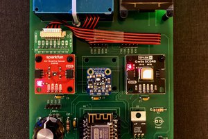
 tdw
tdw
 Jonathan Kelly
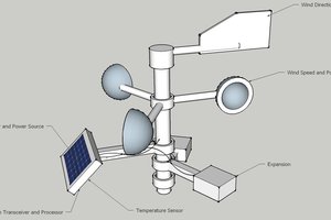
 Ulf Winberg
I like your anemometer. Very well done!