Close
0%
0%

JSCAD Project Box Generator

A script to generate project boxes in JSCAD.

Similar projects worth following
Click here to load the script on the JSCAD website.

Updates:
V1.01 - Added D-Sub Connector shape to cutout shape options.

How to run:

Click here to load the script on the JSCAD website.

Alternative ways to run are to download the script found in the "Files" section and drag and drop the file onto the JSCAD website. You can also copy and paste the text of the script into the JSCAD website editor under the pencil icon and hit the Shift+Enter keys.

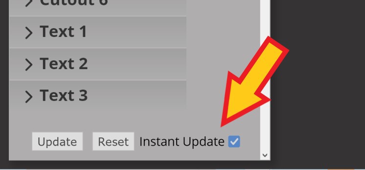
After the script initializes, you will probably want the check the "Instant Update" checkbox if it is not already checked. Once Instant Update is selected, the 3D view will be automatically updated on user parameter changes.

How to export an STL file for 3D printing:

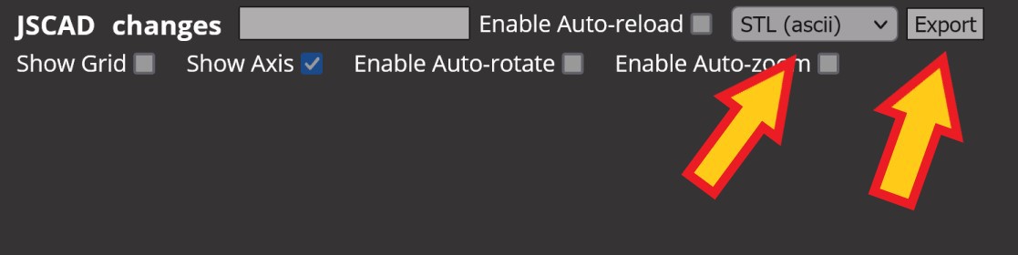
Make sure that the "STL (ascii)" option is selected in the drop down menu at the top of the screen. Then click the "Export" Button. In Firefox, it may not give you any notice that a file was downloaded but the file should be in your downloads folder.

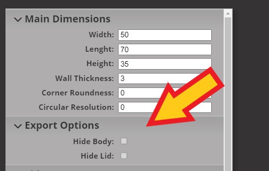
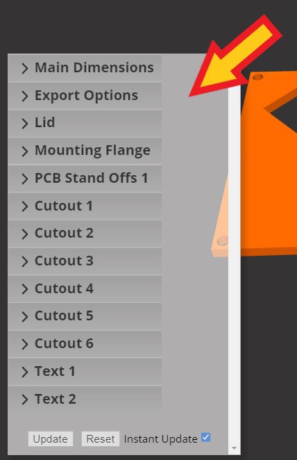
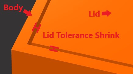
By default the Body and Lid of the box are exported in the same file as a single model. You would have to split the model in your slicing software. You can also just export the Body or Lid as a single model by hiding the opposite part under the "Export Options" group in the User Preferences menu on the left of the screen. Hide the Lid and then click the Export button for the Body STL. Then hide the Body and click the Export button for the Lid STL.

Adding more than the default number of Cutouts, Text, or PCB Standoffs:

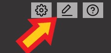
Click the pencil icon in the upper right corner of the screen.

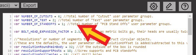
On the first 3 lines, change the number for the NUMBER_OF_X variables to your desired number and then click the SHIFT+ENTER keys to rerun the script. The number of groups should be updated in the User Preferences pane.

Notes:

  • The values is JSCAD are technically unitless but for the intended use case: 1 = 1 millimeter.
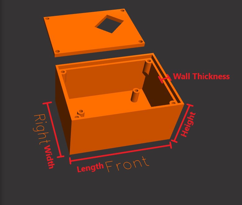
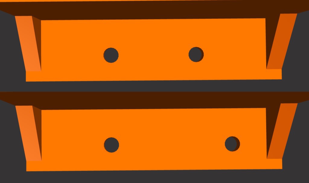
  • The sides are defined by what side of the box is shown when using the JSCAD camera view hotkeys. ('f' Front, 'b' Back, 't' Top, 'c' Bottom, 'l' Left, 'r' Right)
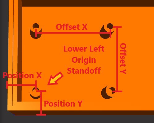
  • The origin point (0, 0) for positioning Cutouts/Text is the bottom left corner of the chosen wall as viewed from the JSCAD camera view hotkey.
  • The Dot Vent type can use a lot of processing power if you try to use a large number of dots.

project_box_generator_101.js

JSCAD project file. A plain text script file. Version 1.01

x-javascript - 49.79 kB - 11/13/2022 at 01:40

Download

  • Description of User Parameters

    Eric Ljungquist11/03/2022 at 20:19 1 comment

    The user parameter pane is at the bottom left of the screen. Clicking the group headers will expand or hide the clicked group.

    Main Dimensions

    • Width - Outside dimension of box from back to front walls.
    • Length - Outside dimension of box from left to right walls.
    • Height - Outside dimension of box from bottom to top.
    • Wall Thickness - Thickness of the outer to inner front, back, bottom, left, and right walls. The Lid has its own thickness value.
    • Corner Roundness - Radius of the chamfer when rounding the outside corners of the box. If the value is 0 then the corners are not rounded. Inside corners are not rounded.
    • Circular Resolution - Circular objects are made up of smaller line segments. A Circular Resolution of 0 will use the default values for number of segments. Positive values add the given number of segments to the default value. Negative values reduce the given number of segments from the default value.

    Export Options

    • Hide Body - Hide the Body of the box from rendering.
    • Hide Lid - Hide the Lid of the box from rendering.

    Lid

    • Lid Thickness - Depth of the Lid
    • Lid Tolerance Shrink - The gap between the the walls of the body and the edges of the Lid.
    • Screw Hole Diameter - Diameter of the pass through screw/bolt holes in the Lid.
    • Lid Screw Supports - The type of lid screw/bolt attachment points.
      • 'Corner Posts' - Cylindrical posts at all four corners that extend from the bottom to the Lid.
      • 'Middle Posts' - Two cylindrical posts at the middle of the Left and Right side walls that extend from the bottom to the Lid.
      • 'Corner Overhang Brackets' - Cylindrical posts at all four corners that extend from the bottom the screw/bolt to the Lid.
      • 'Middle Overhang Brackets' - Two cylindrical posts at the middle of the Left and Right side walls that extend from the bottom of the screw/bolt to the Lid.
      • 'None' - Skip. No screw/bolts to secure Lid.
    • Screw Support Diameter - Diameter of the cylinder that the Lid screw/bolt secures into.
    • Screw Support Hole Diameter - Diameter of the screw/bolt hole that the Lid screw secures into.
    • Screw Support Hole Depth - Depth of the screw/bolt hole in the post itself. The total length of the screw/bolt would be Lid Thickness + Screw Support Hole Depth.

    Mounting Flange

    • Add Mounting Flange - Select to add mounting flanges/tabs to the left and right sides of the box.
    • Thickness - Height of the horizontal tab.
    • Length - Horizontal distance from the project box wall to the end of the mounting flange.
    • Number of Supports - Total number of triangular supports the attach the mounting flange to the project box body.
    • Support Thickness - The thickness/width of the flange supports
    • Support Size - Length/height of the flange supports.
    • Number of Screw Holes - Number of mounting screw holes in each of the flanges.
    • Screw Hole Diameter - Diameter of the mounting screw holes on the flange.
    • Screw Edge Distance - Distance from the outside edge of the flange to the mounting screw hole.
    • Screw Center Offset - An offset value to shift the position of the mounting screw holes off center.
    • Screw Spread Distance - An offset value to add or remove distance between mounting screw holes.

    PCB Stand Offs

    • Type -Type of standoff to add. 
      • 'None' - Skip. Don't add Stand Offs
      • 'Rectangular Four Posts' - Four cylindrical posts
      • 'Use Custom Position List' - Use a user provided list of points to place Standoffs.
    • Thickness - Diameter on the outside of the standoff cylinder.
    • Height - Height of the standoff.
    • Screw Diameter - Diameter of the screw/bolt hole.
    • Screw Depth - Depth of the screw/bolt hole measured from the top of the standoff down.
    • Position X - Position on the bottom inside wall of the origin standoff on the X axis. The origin standoff is the lower left post.
    • Position Y - Position on the bottom inside wall of the origin standoff on the Y axis. The origin standoff is the lower left post.
    • Offset X - Distance between the origin standoff and the other standoffs on the...
    Read more »

View project log

Enjoy this project?

Share

Discussions

laurin wrote 11/11/2022 at 10:29 point

Are dsub cutouts supported?

  Are you sure? yes | no

Eric Ljungquist wrote 11/13/2022 at 01:53 point

I've added an option for the dsub connectors shape in the cutout list. I left it pretty general purpose though. So you will have to set the size yourself and add your own screw holes with additional cutouts.

  Are you sure? yes | no

laurin wrote 11/21/2022 at 18:07 point

very nice!

  Are you sure? yes | no

Similar Projects

Does this project spark your interest?

Become a member to follow this project and never miss any updates