0%
0%
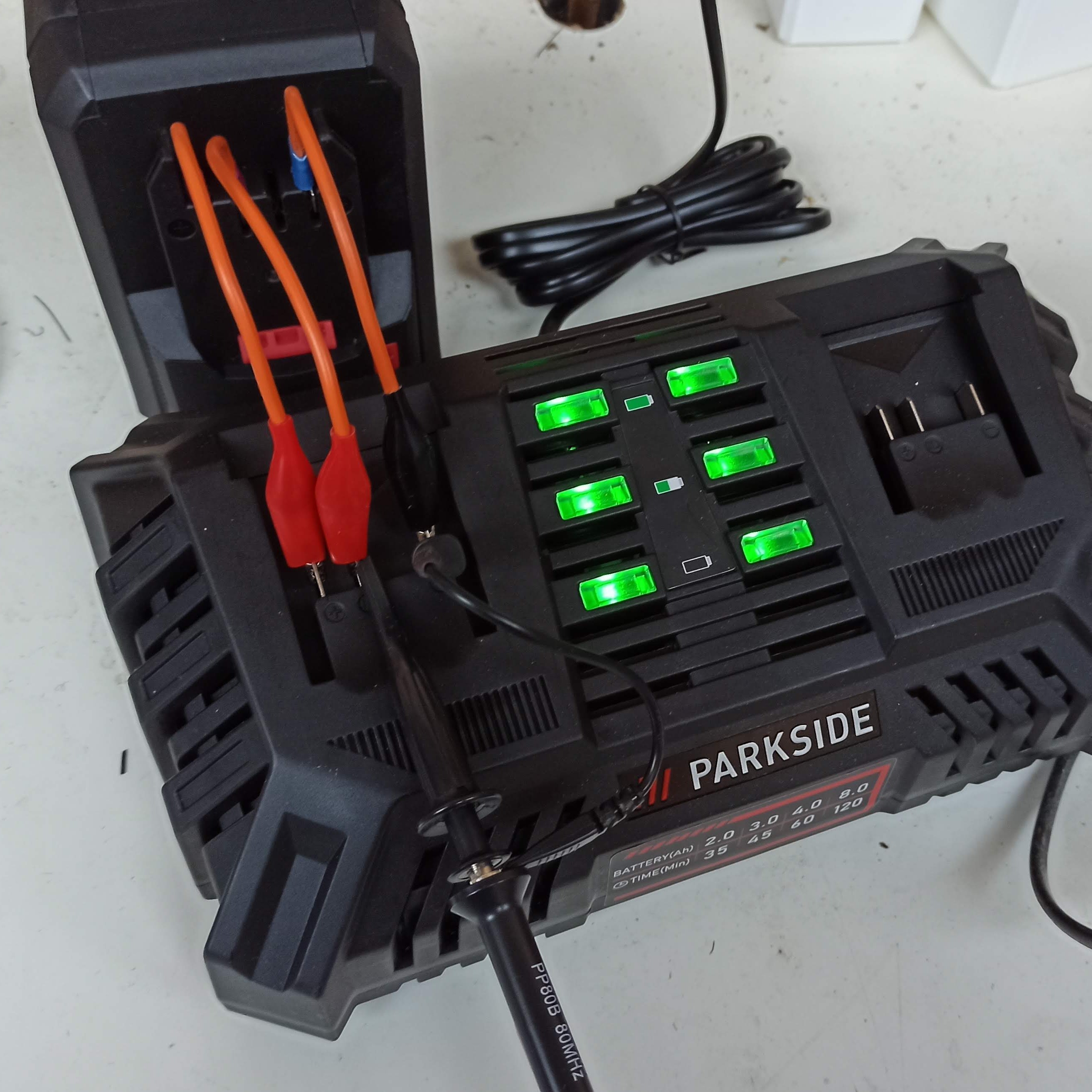
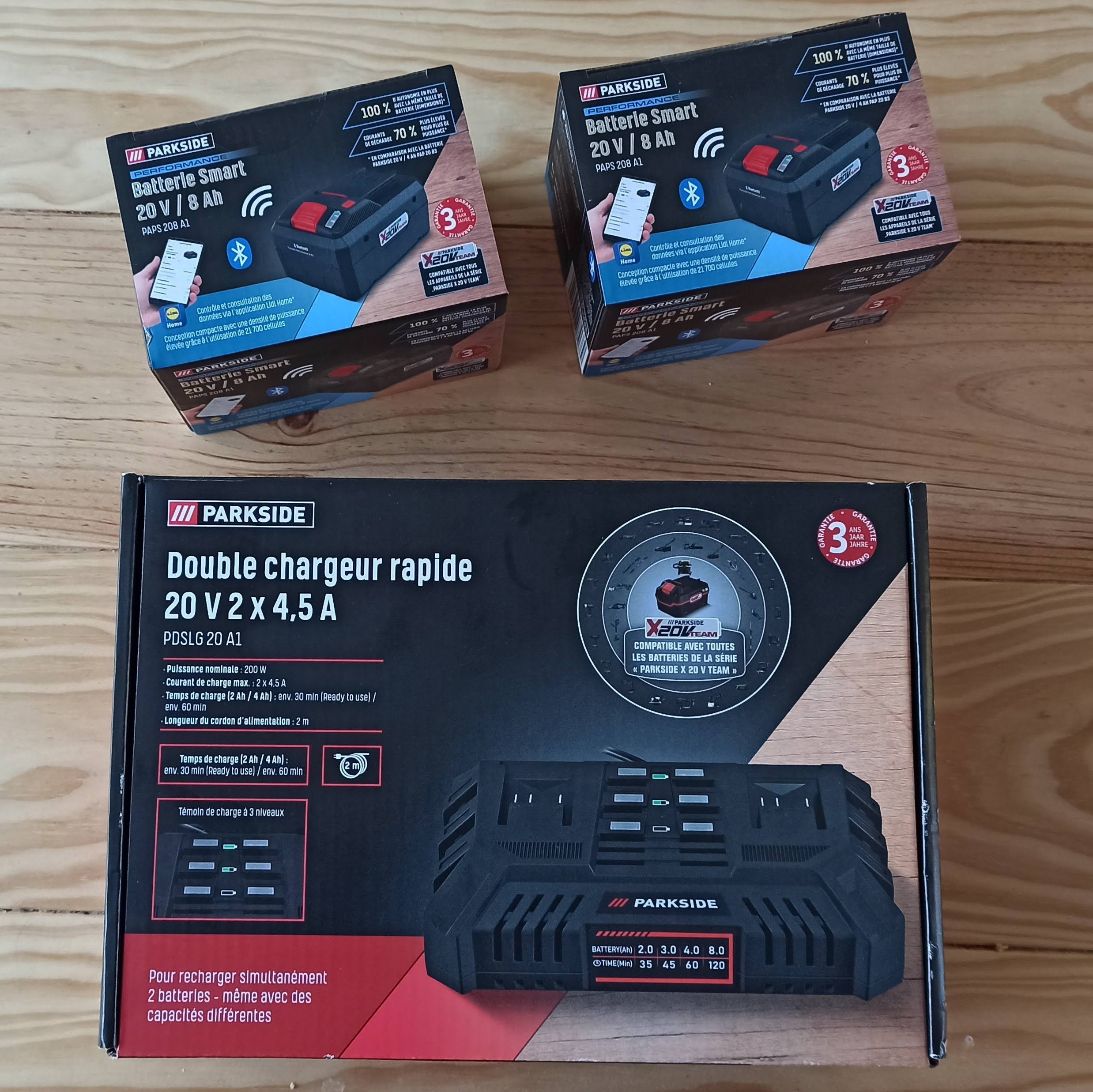
LIDL PARKSIDE Battery hacks
How to use LIDL "smart" battery, to power custom electronic such as robots or ebike, Reverse engineering their bluetooth connectivity..
 Thomas Flayols
Become a Hackaday.io member
Already have an account? Log in.
Just one more thing
To make the experience fit your profile, pick a username and tell us what interests you.
Pick an awesome username
hackaday.io/
Your profile's URL: hackaday.io/username. Max 25 alphanumeric characters.
Pick a few interests
Projects that share your interests
People that share your interests


 Bud Bennett

 Rory
Rory
 Neal
Neal
Hi,
Trying to start charging non lidl battery. Battery comes from kaufland.
With arduino directly connected to gnd and ID and sending
int bb[] = {8,1,3,1,3,2,2,2,3,1,3,1,3,3,1,204}; charge not starting.
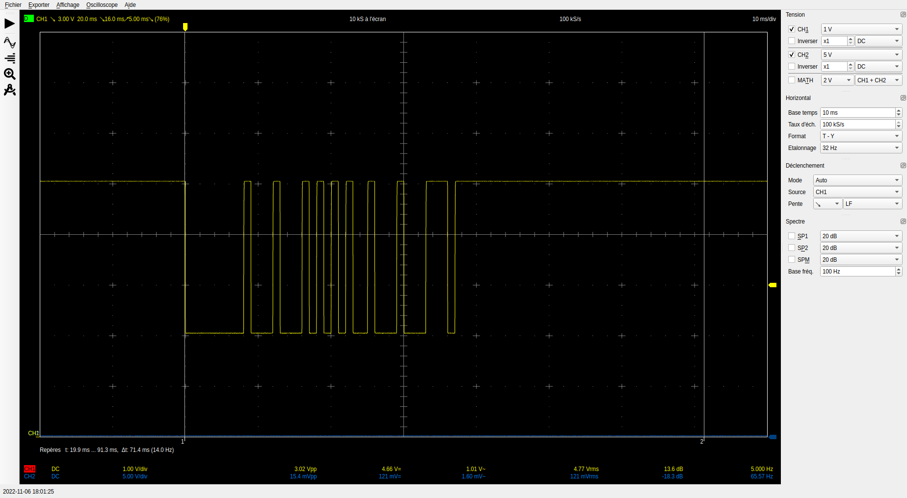
With sigrok aquired another ori lidl battery:
int bb[] = {8,1,3,1,5,2,2,2,1,1,3,1,3,3,1,207}; charge not starting.
Seems little different signal. Arduino is pulling signal low.
What am I missing ?