NuclearPhoenix
Here are some of the most important key facts:
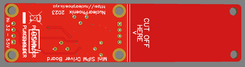
- Compact design: Total size 100 x 25 mm. 51 x 25 mm area for electronics and additional 49 x 25 mm to mount a small scintillator.
- Input voltage: 3.2 V - 5.5 V.
- Low-voltage device: No HV needed like with a photomultiplier tube.
- SiPM voltage range from 27.5 V to 33.8 V.
- Low power consumption: <5 mA @ 5 V in standard operation.
- Adjustable gain for the SiPM pulses, also affects pulse decay time and therefore dead time.
- TTL output for counting pulses or time-over-threshold applications.
- Additional raw pulse output if you want to manipulate the signal or use it for spectroscopy.
- Dead time only limited by the speed of the scintillator and the gain. Typically <10 µs.
- Only needs an additional cheap microcontroller to, for example, build a simple scintillation counter.
More information can also be found in the GitHub repository...
Ok nice, but how do I get it?
- DIY version: Download BOM and Gerber files or use Kitspace.
The principle of operation for the detector looks like this:

Files
schematic.pdfPCB schematicapplication/pdf - 62.56 kB - 11/15/2022 at 20:44 |
|
|
BOM.csvPCB BOMapplication/vnd.ms-excel - 1.56 kB - 11/15/2022 at 20:44 |
|
|
Components
- 1 × MicroFC-60035 SiPM The silicon photomultiplier used with the scintillator
- 1 × Mini SiD PCB Production-ready gerber file in GitHub repo or Kitspace
- 41 × Components for PCB See BOM for exact parts
- 1 × Scintillator For example NaI(Tl)
Project Logs
Collapse
-
Revision 4.1 (design changes and enhancements)
NuclearPhoenix • 03/01/2024 at 12:22 • 0 commentsJust updated the GitHub repository for the Mini SiD for a smaller revision 4.1 launch.
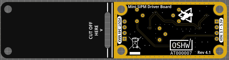
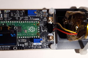
This new board version is mostly a board layout and design update, but there are also a number of other changes that improve on the previous version.Here are some images of the new PCB. This time I chose black with ENIG to align with the latest Open Gamma Detector revision:
![]()
![]()
Changelog:
- Decreased size of the electronics section. Board partitioning is now 50:50 electronics and scintillator.
- New voltage reference chip: This change improves the input voltage range down to 3.1 Volts and decreases power consumption by about 1mA @ 5V.
- Changed location of the SiPM input protection diodes to the comparator only. Prevents clamping of the raw signal if you need it.
- Added AC coupling with PZC component to the comparator input.
- Larger bulk decoupling caps and higher voltage rating for the 100nF MLCCs.
These changes should make the device even more useful while still holding true to the form factor and remaining cheap to build due to the single sided components and part selection. Also, the new silk screen and PCB layout in general are _a lot_ cleaner now. On top of that, the decrease in power consumption is also very nice to have. Let me know what you think!
Check it out on GitHub: https://github.com/OpenGammaProject/Mini-SiD
I also post updates about all of my different projects on my own website now, check it out: https://nuclearphoenix.xyz/2024/03/01/mini-sid-update
-
Updated SiPM Carrier Boards
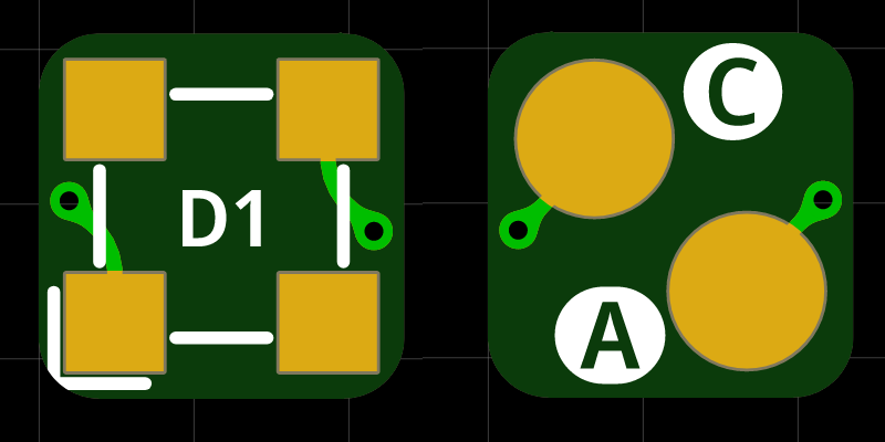
NuclearPhoenix • 02/16/2024 at 20:38 • 0 commentsI reworked the SiPM carrier boards a little in terms of the layout and also used the opportunity to make a board for the 3mm MicroFC SiPM from onsemi. This will definitely come in handy if someone wants to play around with these little LYSO sticks (4x4x20mm or so). The files for the 3mm carrier board can be found on GitHub: https://github.com/OpenGammaProject/Tiny-3mm-MicroFC-Carrier-Board
At 6x6mm, the board is slightly larger than a 4x4mm LYSO scintillator face, but it really couldn't be much smaller and it should work reasonably well regardless.
Overall, the layout of all boards is now tidier and, above all, the important connections are all a lot more clear better marked. I also reduced the distance between the individual SiPMs a little in the 2x2 array. The circuit is otherwise identical.
Here are the latest PCBs:
![]()
![]()
![]()
![]()
-
OSHW certificate is done
NuclearPhoenix • 11/29/2023 at 21:26 • 0 commentsJust updated the silk screen on the PCB one last time, because the OSHWA certificate was just issued and I added the mark. Like I said last time, there are no changes in the actual hardware, I only updated the mark on the PCB, that's it. Cheers!
-
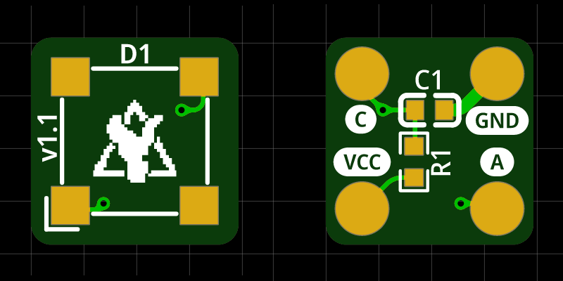
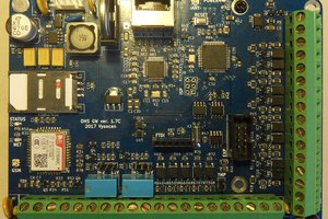
Updated 2x2 SiPM Array
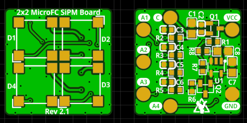
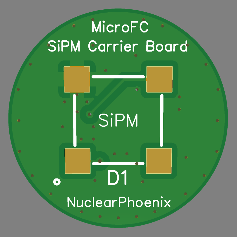
NuclearPhoenix • 11/24/2023 at 17:33 • 0 commentsJust did a quick rework of the 2x2 MicroFC SiPM array PCB, added the temperature compensation from the single PCB and cleaned up the layout in general. It's now 2x2cm in size and still keeps the easy solderability for the four SiPMs (results in a fill factor of ~40%), while also adding the ~21mV/K slope for the power supply.

Front side with only the four SiPMs 
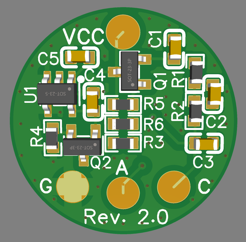
Back side with all the other components If you want to use it, just connect your power to the "VCC" pad, ground to "GND" and then the SiPM anodes to the Mini SiD. You can check the set voltage at the "C" pad on the PCB. If you don't want to use the extra circuitry, you can just solder your power straight to the "C" pad and not bother with the other circuitry. However, you'll still have to solder the low-pass filters for each SiPM, otherwise they won't work.
You can find all the files here: https://github.com/OpenGammaProject/MicroFC-SiPM-Array-Board
Let me know what you think!
-
Revision 4 is finally here
NuclearPhoenix • 11/23/2023 at 11:58 • 0 commentsI finally came around to finish the PCB layout for the latest (and probably last honestly) hardware revision of the Mini SiD. In short, this is a small-ish quality-of-life update with some nice changes that should make it easier to use, while still not changing a whole lot fundamentally.
This is what the new PCB looks like, I still need to get the OSHWA certification for this again, so the files are not completely final, altough everything's functional. The files and all the additional info can be best found on GitHub: https://github.com/OpenGammaProject/Mini-SiD
![]()
![]()
Changes in this revision:
- Switched from a 2-layer PCB to a 4-layer PCB for much better signal integrity.
- Improved PCB layout and shielding in general.
- Decreased length of the electronics section by 2 millimeters.
- Slightly more filtering for the SiPM output voltage.
- Consolidated all the diodes to use the same chip to reduce BOM clutter.
- The pulse discriminator reference, input resistor and power supply feedback path all now use much tighter tolerance resistors with less temperature dependence. That way it's less susceptible to temperature changes.
- The pulse discriminator range has been slightly decreased for easier setting the correct voltage.
I think these changes are a great way to expand upon the last version that already worked well enough to be usable. It also marks a great point to say this project is more or less completed. It's usable, it works great and IMO there is not much that can be changed anymore without some fundamental changes. So thanks to everyone for your support and posting your interest and suggestions. Feel free to continue doing so!
There will be one update when the OSHWA certifies the hardware again, so expect that in the next couple of days.
-
News on a final revision
NuclearPhoenix • 09/20/2023 at 15:22 • 0 commentsHello there, this is just a very quick update on the state of the project since I haven't reached out to you in quite a long time. I've investigated some issues with the temperature dependency of the threshold and the gain. It's not a big issue, but it can be annoying if you use the board in an environment where the temperature can change over a much wider range than indoors. You can always increase the threshold a little bit above the needed voltage to have a small safety margin, so it won't affect you nearly as much.
These problems will be fixed with a slight change in parts and more optimized circuitry. I'm going to do one final updated revision of the board with these changes and maybe some other slight improvements that come to my mind. I'll update you once the work is done and the hardware is ready, so stay tuned!
On another note, the Mini SiD is sold out on Tindie, so thank you all for your interest in this project and the support. You can still get some of the Tiny MicroFC breakout boards if you want, the sale is still on until the end of september.
Cheers!
-
End Of Summer Sale
NuclearPhoenix • 08/31/2023 at 09:51 • 0 commentsFrom September 1st to 30th there will be a site-wide sale (-10%) on my Tindie Store, including the Mini SiD, the Tiny MicroFC SiPM breakout board and the Open Gamma Detector. No limit on the number of uses or products!
Tindie: https://www.tindie.com/stores/nuclearphoenix/
-
Tiny SiPM Boards on Tindie
NuclearPhoenix • 08/22/2023 at 10:36 • 0 commentsFinally, the Tiny MicroFC SiPM breakout/carrier boards are now available on Tindie! I have added some volume discounts for the PCBs and purchase options together with the Mini SiD and Open Gamma Detector.
Link to the store page: https://www.tindie.com/products/31304/
Thanks to all the feedback and demand from you guys for the SiPM carrier boards. It's been long overdue to add these to Tindie so that you can get the PCBs together with the detector electronics.
-
Last chance for Tindie
NuclearPhoenix • 08/02/2023 at 09:31 • 0 commentsJust wanted to let you know that there are only 3 of the fully assembled Mini SiD boards left on Tindie. This is the final batch, after that there will be no new production run. So if you want to get your hands on one, this is the last chance.
-
Temperature-compensated SiPM carrier board
NuclearPhoenix • 07/26/2023 at 18:19 • 0 commentsHi there!
Here is a new and updated revision of the MicroFC SiPM carrier board: It now has some extra circuitry for temperature gain compensation! The overall size of the PCB and the solder pads have not changed at all and the bias filtering is also still on there. In addition to that, you can also use it without any of the additional electronics on it too. Don't need temperature compensation or any of the filtering? Just leave out all the components on the back side and solder directly to the anode and cathode pads for the SiPM.
If you do want to use the compensation circuit, a new BOM, Gerber file and schematic have been uploaded to GitHub. Kitspace should update too in the next couple of days (hopefully). Here is a link to the repo: https://github.com/OpenGammaProject/MicroFC-SiPM-Carrier-Board
It works completely passively without any sort of user intervention. It's based on an NTC thermistor that sits on the back side of the PCB, which is a big plus for temperature accuracy since it's on the same board as the SiPM. It's also low-power enough so that there is no unnecessary self-heating of the PCB. Just be sure to increase the SiPM PSU voltage a little bit as the compensation circuit initially drops a couple of 100mV to increase the temperature range without any need for readjustment. And ideally, you'd want to set the correct voltage at around normal ambient temperature for the correct tracking range (e.g. ~29.5V @ 25C).
Most of the research and testing has been done by Sebastian D'Hyon, so big thanks to him.
Finally, here are some screenshots on what the new board looks like:
![]()
![]()
Cheers!


Build Instructions
Collapse
-
1OPTIONAL: Solder SiPM carrier board components
This is an optional step if you're using the carrier boards. If you're not and just soldering wires directly to the SiPM or doing it otherwise, skip this part.
All the SMD parts, the pin header and the SiPM itself. Orient yourself with the schematic and BOM. You can solder the pin header or, even better, use small wires instead.
Optionally, you can also skip this part and use the raw SiPM on its own and try to solder some small wires directly to it. That's not recommended though, as this whole process is quite delicate.
-
2Couple SiPM with scintillator
Center the SiPM on the scintillator crystal and put some silicon grease between the two parts to optimize the coupling (and minimize reflections)
-
3Wrap scintillator assembly
Use black electrical insulation tape or similar non-transparent material to wrap the whole assemby, but watch out for the connector or cables, of course. This will reduce light passing to the SiPM to an absolute minimum, otherwise it won't work properly. You should use multiple layers of tape just to be sure.
 vysocan76
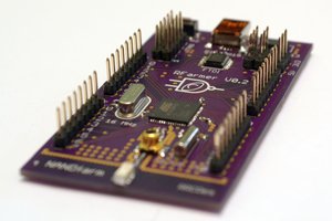
 Radu Constantin