-
Project Log 64: DIY Linear Actuator.¹
07/21/2023 at 13:35 • 7 comments21/07/2023, Friday, 10:16.
For some reason this last week got me too lazy to do anything at all...
Well, I will just leave this here and see what I can think of...
----------------------------------------------------------------------------------------------------------
Well, I wrote the DIY iron-air battery with a "¹", because I thought I would be able to understand and replicate the papers that I saw...
But, as you can imagine, I did read stuff, and it all came to: either I don't have the equipment to replicate their methods, either they didn't talk about their methods.Soooooooo... It is what it is, I suppose.
----------------------------------------------------------------------------------------------------------
Well, even though I'm trying to make the "sketch" of the mech with these project logs since Project Log 54, I don't quite know where to go from here.
https://hackaday.io/project/188391-diy-mechexoskeleton-suit/log/220205-project-log-54-just-one-last-tryI think I will make this project log about the linear actuators of the mech/exosuit.
Like in project log 58, were I talked about zip chain actuators for both flexible and rigid linear actuators, I believe I will stick to that idea.
https://hackaday.io/project/188391-diy-mechexoskeleton-suit/log/220958-project-log-58-diy-electric-motor
One thing I never liked about the hoist/winch mechanism is it lack of efficiency, which the zip chain would (supposedly) solve.But now I think I got myself in another little conundrum.
You see, since the zip chain actuator is, well, a chain actuator, the logics of torque, speed and so on will still be applied to it.
And thus, I can reach a point that I don't really need the reduction gear from James Bruton which I was thinking on using.Which needs to be calculated, and right it is Sunday, and I'm not in the mood, lol.
----------------------------------------------------------------------------------------------------------
PS: I talked about the rack and pinion to the ChatGPT because it is easier to calculate and it is basically the same thing.
![]()
I asked ChatGPT:
"ChatGPT
To determine the number of teeth required for the rack and pinion mechanism, we need to consider the relationship between rotational motion and linear motion.For a gear, the linear speed (V) can be calculated using the formula:
V = π * d * RPM / 60
Where:
V is the linear speed
d is the diameter of the gear
RPM is the revolutions per minuteIn your case, with a gear diameter of 10 cm and an RPM of 30, the linear speed would be:
V = π * 10 * 30 / 60 = 15π cm/s ≈ 47.1 cm/s
Now, if you want a 1:1 output, the linear speed of the rack (which is the same as the pinion's linear speed) should be equal to 47.1 cm/s. Therefore, you need to choose the number of teeth on the rack and pinion such that the linear speed matches.
Let's assume the number of teeth on the pinion is P and the number of teeth on the rack is R. The gear ratio (GR) can be calculated as:
GR = R / P
For a 1:1 output, the gear ratio should be 1. Therefore:
1 = R / P
Now, to achieve a 10:1 output, the gear ratio would be 10:
10 = R / P
To find the number of teeth, we need to consider the pitch radius (radius corresponding to one tooth) of the gear. The pitch radius (Rp) can be calculated as:
Rp = d / 2
Where:
Rp is the pitch radius
d is the diameter of the gearIn your case, the pitch radius would be:
Rp = 10 cm / 2 = 5 cm
Now, we can calculate the number of teeth using the following formulas:
For 1:1 output:
P = RFor 10:1 output:
P = R / 10The number of teeth can be calculated using the formula:
T = 2 * π * Rp / pitch
Where:
T is the number of teeth
Rp is the pitch radius
pitch is the pitch of the teeth (distance between adjacent teeth)The pitch can be calculated as:
pitch = linear speed / RPM
Let's calculate the number of teeth for both scenarios:
For 1:1 output:
pitch = 47.1 cm/s / 30 RPM = 1.57 cm/toothP = R = 2 * π * 5 cm / 1.57 cm/tooth ≈ 6.37 teeth
Since the number of teeth cannot be fractional, you might need to round up or down to the nearest whole number. In this case, you could use 6 teeth for both the pinion and rack.
For 10:1 output:
pitch = 47.1 cm/s / 30 RPM = 1.57 cm/toothP = R / 10 = 2 * π * 5 cm / 1.57 cm/tooth ≈ 0.637 teeth
Again, rounding up or down to the nearest whole number, you could use 1 tooth for the pinion and 10 teeth for the rack.
Please note that these calculations assume an idealized scenario, and in practice, you might need to consider factors such as backlash, tooth strength, and smoothness of operation in your gear and rack design."
----------------------------------------------------------------------------------------------------------
Well... I didn't understood a hint on what the heck ChatGPT was talking, but I think I kinda got the gist of it.
Basically, if I were to make a 10:1 ratio, I would need to take into consideration both the diameter and number of teeth.
If the gear/pinion has a number of teeth "X" (let's say, 10 teeth), the pinion and the rack should have the dimensions (size, length etc) allowing for the rack move a "Y" amount of length and the pinion rotate a "Z" amount of times to allow everything to rotate the distance you want.
A giant 2 meter wide gear/pinion with 10 teeth would move way faster at a rack with 20 teeth and 1 meter of length (assuming the physics would work out for this hyphotetical example) rather than a gear with 10cm of diameter and 20 teeth in a rack with 100 teeth and merely 30cm of length.
I guess one easy way of making a rack and pinion would be to use the circunference of a circle multiplied by the times you want the reduction to occur and then add the same number of teeth that would allow for the reduction.
So, a 10:1 reduction ratio would force me to take a 2cm diameter pinion, which would be 6.28319cm, then insert 5 teeth on the gear and other 50 teeth on the rack with 62.8319cm of length. (I think).
... Or not, bruh, this is wrecking my brain.
----------------------------------------------------------------------------------------------------------
I did found a promising open source zip chain actuator, the problem is that I'm starting to doubt whenever or not this aproach is really practical.
https://www.thingiverse.com/thing:1283288
![]()
I think I will be forced to keep up with the old hoist/winch mechanism... But I don't trust on its efficiency... y=y
By the way, the article chooses the C option. But I would keep with the B option, a compound pulley loses 5% to 15% of efficiency per pulley, and the third kinda is a compound pulley.
The problem with telescopic cable-driven actuator is not lifting, it is pulling. You need a double actuation for this to be useful, and how do you do that?
The article just showed: put a hoist connected to the tip and another connected to the pulley system.
----------------------------------------------------------------------------------------------------------
Also, I just saw this eccentric gear and I quite liked it.
Although you can't really use planar laser cutting for it, I do like its simplicity.
It is a 1 teeth gear with a 10 teeth bigger gear, giving it a 10:1 gear reduction ratio in an apparently studier and simpler gear than a cycloidal gearbox or a conventional spur gearbox.This guy teaches how to program/calculate an eccentrical cycloidal gear.
However, I would advise you to make a version that is way thicker and with a double helical shape.
----------------------------------------------------------------------------------------------------------
By the way, one important thing: all these actuators will be using bearings and all of these bearings need to sustain the entire weight of the suit.
I was thinking on using car bearings, but these are kinda expensive to simply go buying around, but I have an idea.
Basically, cross roller bearings are a well-used type of bearing that is normally meant for heavy duty applications, even the Hacksmith used those on the hands/arms of their 6 ton lifting power loader.
I will be using this guy's tutorial.
Of course, you can just buy ball bearings on the internet, these are kinda cheap and come in the hundreds.
I'm leaving this here to make use of it later, for some reason I feel way more indisposed than usual right now...
----------------------------------------------------------------------------------------------------------
Bruuuuh... I'm really not on the mood right now to 3D model the actuator... But I think I will stay with the linear hoist actuator... Or not... Every time I think about it I feel like I'm overlooking a lot of stuff, every time I think I should switch to hydraulics or the reversebly actuated pneumatic artificial muscle instead...
I say this because the linear actuator will be under compression, but an hydraulic actuator will transfer the loads to the HDPE composite as tension on its walls, which is the strength of the HDPE.
Actually, no...
I just researched the overall characteristics of HDPE and UHMWPE (or HMPE) and it showed extremely different characteristics from which I remember seeing/posted here before.
Unfortunately, I didn't straight up wrote the values, but it were close to 90 MPA, now I can only find links saying that HDPE can only hold up to 26 MPA of tensile strength and up to 30 MPA of compressive strength.
------------------------------------------------------------------------------------------------------------------------------
Well, while I got disappointed with my own mistake of simply ignoring the problems until they hit my face, I got wondering how I could surpass said problems.
If you're not catching my drift, it is the fact that the HDPE and/or UHMWPE plastics, although very useful, are still plastics. So they may or may not be capable of being used as the main structure of the Mech/Exosuit.
If you convert the compressive/tensile strength that these have of +/- 30 MPa to bar or KgfCm², you would only get a maximum strength of 300 kg for every part.
Of course, this proportion was taken out of my ass and may not be in accord with reality, but you must remember that PSI (pound per square inch) and KgfCm² (kilogram force per square centimeter) can be seen as the simple force applied to a certain area.And as such, you could (probably) take the material characteristics and "translate" it to the maximum force said material would be ale to withstand in the given situation.
If I want this material to withstand 3000 kg, I would need it to be, supposedly, 10 times thicker than one would normally need for a steel material, for example.
(I think)
Steel has a tensile strength of 400 to 550 MPa and a compressive strength of 250 to 400 MPa (for structural steel).
A 5 ton hydraulic cylinder that works at a pressure of 16 MPa (160 bars) has 10mm of wall thickness and weights around 10kg.Even if I don't actually make an hydraulic cylinder out of HDPE, I would still need to make things with more or less 100mm (10cm) of thickness for structural resilience.
... I think.
------------------------------------------------------------------------------------------------------------------------------
Also, I was thinking on a way of making steel/metal parts in general in a DIY setup and on the cheap. Although I don't know how well I would be successful on such endeavor.
So, the idea would be more or less like this:
1: Make iron oxide
2: Transform the Iron oxide into pure iron powder with the reduction reaction.
3: Mix said powder with the ideal proportion of iron and carbon to generate steel.
4: Place the mixture in a container with little oxygen/air.
5: Place the thermite around this container and in a place away from people.
6: Activate the thermite and melt the metal
7: Transfer the liquid steel to the desired mold.The idea would be to use the thermite reaction involving iron oxide and pure aluminium powder in order to reach the necessary temperatures.
However, the problem is how to transfer the heat from the reaction to the thing you want to melt without having both liquid metals mixing with each other and making useless slag.
My idea was to use either copper or even sand, since sand is a good thermal "battery", so to speak.
Basically, homemade thermites aren't that hot/powerful, so I thought that maybe the copper would survive, since it would only transfer the heat instead of being the thing that melts.Plus, some electric kilns work by inserting the electric heating element on the walls of the kiln, heating its insides and then the crucible with the material to be melted. It wouldn't be much different from this idea.
(there are more videos on this series, by the way)
And even then, I doubt I would be able to make pieces with enough precision and strength.
But hey, if you want to do it, go for it.
------------------------------------------------------------------------------------------------------------------------------
Also, dekutree64 just gave an interesting suggestion that I didn't consider while writing this project log: using aluminium.
Aluminium melts at "only" 660 ºC, unlike steel, that needs twice or trice this temperature to be molten and is way easier to handle.
This kiln is way easier to build and use than previously mentioned electric kilns (the guy easily melts aluminium), besides, I would bet that if you take a really buffy microwave, you would be able even melt steel.
But I would try to make an "open kiln", let's say, tearing open a microwave and "glueing" the magnetron to the ceramic wool with the silicon carbide crucible inside of it rather than making all this work for a small crucible that would fit inside a microwave.
You would be able to make something more akin to an actual kiln this way.
And maybe you wouldn't even need to make a silicon carbide kiln, using silicon carbide plates/blocks/pieces like the heating element on conventional electric kilns.
Like this one, he cut/broke a silicon carbide griding disk for the heating element.
------------------------------------------------------------------------------------------------------------------------------
Also, like Dekutree64 mentioned in his comment: you could use scrap aluminium for that.
However, you would need to be careful to actually take aluminium instead of Tin or stainless steel. And you would also need to take off the paint and the plastic inliner on soda cans, the best way I could find was to just heat the can until the plastic and the paint just peel off.
You could do it after cutting everything in little pieces (not powder, pieces) and throghouly washing it until it is relatively clean.
------------------------------------------------------------------------------------------------------------------------------
Although it wouldn't be that stronger than extruded aluminium, you could use a few "cheats" to heat treat it in order to increase its strength.
For example, in this video the guy shows a few heat treatments in order to make aluminium castings stronger. Not to mention that you could add a little bit of silicon metal and/or other materials in order to make something as strong as aerospace aluminium.
------------------------------------------------------------------------------------------------------------------------------
ChatGPT:
"It seems like there might be a slight mix-up in the alloy designations you provided. The common aerospace aluminum alloys are 6061 and 7075, not 7071. Let's take a look at the materials found in these two popular aerospace aluminum alloys:
- Aluminum 6061: Aluminum alloy 6061 is a versatile and widely used material in aerospace applications due to its good combination of strength, workability, and corrosion resistance. It typically contains the following elements:
- Aluminum (Al): The primary element, constituting the majority of the alloy.
- Magnesium (Mg): Typically around 1.0% to 1.2%. It provides strength and increases the alloy's heat-treatability.
- Silicon (Si): Usually around 0.4% to 0.8%. It aids in improving the alloy's casting properties and contributes to strength.
- Iron (Fe): Usually less than 0.7%.
- Copper (Cu): Typically around 0.15% to 0.4%. It enhances strength and corrosion resistance.
- Zinc (Zn): Usually less than 0.25%.
- Titanium (Ti): Sometimes present in trace amounts for grain refinement and control.
- Aluminum 7075: Aluminum alloy 7075 is known for its exceptional strength-to-weight ratio and is commonly used in aerospace and high-performance applications. It typically contains the following elements:
- Aluminum (Al): The primary element, making up the bulk of the alloy composition.
- Zinc (Zn): Typically around 5.1% to 6.1%. It is a significant alloying element that enhances strength.
- Magnesium (Mg): Usually around 2.1% to 2.9%. It further improves the alloy's strength and contributes to its heat-treatability.
- Copper (Cu): Typically around 1.2% to 2.0%. It provides additional strength and hardness.
- Chromium (Cr): Sometimes present in small amounts, aiding in improving corrosion resistance.
Both 6061 and 7075 aluminum alloys are widely used in the aerospace industry for various components, such as aircraft structures, wings, fuselage parts, and more, due to their favorable mechanical properties and lightweight characteristics. The specific composition and processing of these alloys can vary depending on the intended application and desired properties."
------------------------------------------------------------------------------------------------------------------------------
So, in resume, you would need a few grams of each material for your homemade 6061/7075 aluminium alloy.
Also, what defines aluminium 6061 and 7075 grades are more related to its heat treatment rather than its alloying, but you can only heat treat to this extent due to its alloying.
"The tensile strength of pure aluminium is around 90 MPa but this can be increased to over 690 MPa"
Source: https://www.azom.com/article.aspx?ArticleID=2863
(I searched other sources and the compressive strength increases to a similar extent, around 600 MPa)
------------------------------------------------------------------------------------------------------------------------------
"Aluminum alloys 6061 and 7075 are both popular and widely used in various industries due to their excellent mechanical properties and high strength-to-weight ratio. They undergo different heat treatments to enhance their properties, making them suitable for specific applications. Below are the common heat treatments for each alloy:
Heat treatments for Aluminum 6061:
- Annealing (O Temper): This is the softest and most ductile condition of 6061 aluminum. It involves heating the alloy to around 775°F (413°C) and then allowing it to cool slowly in the furnace. This treatment reduces internal stresses and improves workability.
- Solution Heat Treatment (T4 Temper): The alloy is heated to around 990°F (532°C) for a specific period and then quenched rapidly in water. This treatment dissolves the alloying elements and prepares it for precipitation hardening.
- Precipitation Hardening (T6 Temper): After the solution heat treatment, the material is aged at around 320°F to 350°F (160°C to 177°C) for several hours. This results in the precipitation of strengthening phases, such as Mg2Si, which significantly increases the alloy's strength.
- Artificial Aging (T651 Temper): In this process, the material is artificially aged after the solution heat treatment, which results in improved mechanical properties, especially for thicker sections. The aging is typically done at around 350°F (177°C) for a few hours.
Heat treatments for Aluminum 7075:
- Solution Heat Treatment (T6 Temper): Similar to 6061, the 7075 alloy undergoes solution heat treatment by heating it to around 990°F (532°C) and then quenching it rapidly in water. This treatment prepares the alloy for precipitation hardening.
- Precipitation Hardening (T6 Temper): After the solution heat treatment, the material is aged at about 250°F to 300°F (121°C to 149°C) for several hours, leading to the precipitation of strengthening phases like MgZn2. This significantly increases the alloy's strength.
- Artificial Aging (T651 Temper): As with 6061, artificial aging is applied to 7075 to further improve its mechanical properties, especially for thicker sections. The aging is typically done at around 250°F to 300°F (121°C to 149°C) for a few hours.
It's essential to note that the specific heat treatment processes and parameters can vary slightly depending on the manufacturer and application requirements. Proper heat treatment significantly impacts the mechanical properties of these aluminum alloys, allowing engineers to tailor their performance to meet specific design needs."
------------------------------------------------------------------------------------------------------------------------------
I tried to search for glass fiber aluminium composites, but I couldn't find anything besides actually "gluing" fiberglass/carbon fiber with epoxy on alumnium plates.
![]()
I could only find a few papers on the subject, such as this one (you may need to use the sci-hub to read the entire article:
https://www.sciencedirect.com/science/article/abs/pii/S0925838819325083The articles concludes that the composite was stronger than monolithic aluminium parts.
I think this article is also interesting:
One of the metal matrix composites were made using aluminium metal and aluminium oxide (alumina) powder.
By the way, I think that is hard to find fiber glass aluminium composites because the fiber glass needs to be porpusefuly made for high temperatures, such as silica-alumina ceramic wools for kilns/furnaces.
But I don't know if these kinds of fibers would increase the mechanical strength of such composite, after all, that's not the use for such fiber.
Regular fiber glass can only withstand temperatures to a few hundred degrees, so does basalt fiber and carbon fiber. Also, carbon kinda "kills" aluminium metal, so you wouldn't be able to use carbon fiber either (I think).
You could also use Steel wires/cables for the composite, since these have a waaaay higher melting point.
Kinda silly how I didn't think of such thing before.... humm
I found this article here:
https://www.researchgate.net/publication/279284161_Composites_of_Aluminium_Alloy_Matrix_Reinforced_by_a_Steel_Mesh
------------------------------------------------------------------------------------------------------------------------------
You can still use aluminium for a stator, but it is not well suited for high torque applications (accordingly to Chat GPT).
"Aluminum alloys used for stators in electric motors are typically chosen based on their specific mechanical and electrical properties. Some of the commonly used aluminum alloys for stators include:
- Aluminum 3004: This alloy offers good formability and high strength, making it suitable for stator components that require shaping or bending during manufacturing.
- Aluminum 5052: This alloy has excellent corrosion resistance and good weldability. It is often used in stators that may be exposed to harsh environmental conditions.
- Aluminum 6061: This alloy is known for its excellent machinability and good strength-to-weight ratio. It is used in stators that require high mechanical stability.
- Aluminum 6063: This alloy is prized for its extrudability and is often used in applications where intricate shapes or custom profiles are needed.
- Aluminum 7075: This high-strength alloy is used in applications requiring superior mechanical properties and performance under high loads or stresses.
- Aluminum 8000 series alloys: These alloys, including 8011 and 8079, are commonly used in electrical applications due to their excellent electrical conductivity.
The choice of the specific aluminum alloy will depend on factors such as the motor's operating conditions, mechanical requirements, and environmental exposure. Additionally, in some cases, the alloy may be customized with additional elements to achieve specific performance characteristics.
It's important to note that while aluminum alloys offer advantages such as lightweight and good thermal conductivity, they may not be as suitable for high-power or high-torque applications compared to other materials like iron-based alloys (e.g., silicon steel) or soft magnetic composites (SMCs) due to their lower magnetic permeability. Therefore, the selection of the appropriate alloy should align with the specific requirements of the motor design and intended application."
Also, something I think it would be relevant, since one would probably take aluminium from scrapyards, normally in the form of soda cans:
"Soda cans are typically made from aluminum alloys that are specifically designed for easy fabrication, low cost, and good formability. The most common aluminum alloy used for soda cans and many other daily objects is known as 3004 alloy. The composition of 3004 aluminum alloy is as follows:
- Aluminum (Al): 95.8>#/li###
- Magnesium (Mg): 0.8>#/li###
- Manganese (Mn): 1.3>#/li###
- Silicon (Si): 0.3>#/li###
- Iron (Fe): 0.7>#/li###
- Others: 1.1>#/li###
This alloy is part of the 3xxx series of aluminum alloys, which are known for their excellent formability and corrosion resistance. It can be easily shaped into thin sheets to create cans, making it a popular choice for beverage packaging.
When melting aluminum scrap from soda cans or any other aluminum objects, it's essential to ensure the material is clean and free from any contaminants, such as paint, coatings, or other non-aluminum materials, which could affect the quality of the castings. Additionally, it's important to take proper safety precautions when melting aluminum, as it involves high temperatures. Make sure to work in a well-ventilated area, wear appropriate protective gear, and follow proper procedures to prevent accidents and ensure a successful casting process."
------------------------------------------------------------------------------------------------------------------------------
"Titanium Aluminides (TiAl): These intermetallic compounds offer a unique combination of low density and high strength at elevated temperatures, making them useful for aerospace and automotive applications."
You can find titanium dioxide for a really cheap price online (compared to its metallic counterpart), it is normally used as a pigment, basis for makeup, food additive and/or abrasive element.
"The reduction of titanium oxide (TiO2) with hydrogen gas (H2) typically occurs at elevated temperatures in a controlled atmosphere. The process involves removing oxygen from the titanium oxide to produce titanium metal. This reduction reaction is commonly used in the production of titanium and its alloys. The conditions under which this reduction occurs are as follows:
- Temperature: The reduction of titanium oxide with hydrogen gas usually occurs at temperatures in the range of 800°C to 1,200°C (1,472°F to 2,192°F). The specific temperature can vary depending on factors such as the type of titanium oxide being reduced and the desired reaction kinetics.
- Atmosphere: The reduction is typically carried out in a controlled atmosphere of hydrogen gas. The presence of a reducing gas like hydrogen prevents the re-oxidation of the titanium during the process.
- Pressure: The reduction process can be conducted at atmospheric pressure or at slightly elevated pressures, depending on the specific setup and requirements of the production process.
- Reaction Time: The duration of the reduction process can vary based on factors such as the temperature, particle size of the starting materials, and the desired extent of reduction. Generally, the reduction time can range from several hours to several days.
- Catalysts: In some cases, catalysts may be used to enhance the reduction reaction kinetics and lower the required temperature. For example, iron powder or other transition metal powders can act as catalysts in the reduction of titanium oxide.
It's important to note that the reduction of titanium oxide with hydrogen is an energy-intensive process and is typically carried out in specialized equipment such as fluidized bed reactors or vacuum furnaces. The resulting titanium sponge produced from this reduction process is further processed to obtain usable titanium metal or used as a feedstock for producing titanium alloys.
The reduction of titanium oxide is a fundamental step in the production of titanium, which is a critical material in various industries, including aerospace, automotive, medical implants, and more."
Titanium aluminides are a class of intermetallic compounds that consist primarily of titanium and aluminum. They are known for their lightweight, high-temperature strength, and good corrosion resistance, making them valuable for aerospace and other high-performance applications. The exact composition and processing steps can vary depending on the specific alloy and its intended use, but I can provide a general overview of the process.
1. Alloy Composition: The composition of titanium aluminides typically includes a range of elements to achieve the desired properties. In addition to titanium (Ti) and aluminum (Al), other elements such as niobium (Nb), tantalum (Ta), and vanadium (V) may be added to enhance certain characteristics. The specific percentages of each element can vary widely based on the alloy's intended properties.
2. Melting and Alloying: The process of making titanium aluminides generally involves melting the constituent metals together in a controlled environment, such as a vacuum arc furnace or an induction furnace. The steps involved are as follows:
a. Preparation of Raw Materials: High-purity titanium, aluminum, and any other alloying elements are weighed and mixed according to the desired composition.
b. Melting: The raw materials are loaded into a crucible within the furnace. The furnace is then heated to temperatures exceeding the melting points of the metals. Once the metals are molten, they are thoroughly mixed to ensure homogeneity.
c. Alloying: Alloying elements are added to the melt as needed to achieve the desired composition. The melt is stirred or agitated to ensure proper mixing.
3. Casting: After the alloy is properly mixed and homogenized, it can be cast into the desired shape. There are various casting methods that can be used, such as:
a. Ingot Casting: The molten alloy is poured into a mold to solidify into a large ingot. The ingot can later be processed into various forms, such as sheets, bars, or other shapes.
b. Directional Solidification (DS): This technique involves controlled solidification of the alloy in a specific direction, which can lead to improved microstructure and properties.
4. Hot Working: Titanium aluminides often undergo hot working processes to refine the microstructure and improve mechanical properties. Hot working typically involves processes such as:
a. Hot Rolling: The alloy is heated to elevated temperatures and then passed through rolling mills to reduce its thickness and improve its mechanical properties.
b. Hot Forging: The alloy is heated and shaped using mechanical force to achieve the desired form and properties.
5. Heat Treatment: Heat treatment is a critical step to optimize the microstructure and properties of titanium aluminides. This typically involves:
a. Solutionizing: The alloy is heated to a specific temperature to dissolve any precipitates or impurities, followed by rapid cooling to trap the desired microstructure.
b. Aging: The alloy is held at an intermediate temperature to allow controlled precipitation of strengthening phases within the microstructure.
The specific details of each step, including temperatures, times, and cooling rates, can vary depending on the alloy and its intended properties. Researchers and engineers continually work to optimize these parameters to achieve the best balance of mechanical, thermal, and corrosion properties in titanium aluminides.
I apologize for not providing specific percentage ranges in my previous response. The exact composition of titanium aluminides can vary widely depending on the specific alloy and its intended application. However, I can provide you with a general idea of the typical composition ranges for some common titanium aluminide alloys:
- TiAl (Gamma Titanium Aluminide):
- Titanium (Ti): Approximately 40-48>#/li###
- Aluminum (Al): Approximately 52-60>#/li###
- Ti3Al (Alpha-2 Titanium Aluminide):
- Titanium (Ti): Approximately 89-92>#/li###
- Aluminum (Al): Approximately 7-10>#/li###
- Other elements (e.g., trace amounts of oxygen, nitrogen)
- TiAlNb (Titanium Aluminide with Niobium):
- Titanium (Ti): Varies, but often around 45-48>#/li###
- Aluminum (Al): Varies, but often around 51-54>#/li###
- Niobium (Nb): Typically around 2-5>#/li###
- Other elements (e.g., trace amounts of vanadium, iron, etc.)
- TiAlTa (Titanium Aluminide with Tantalum):
- Titanium (Ti): Varies, but often around 40-45>#/li###
- Aluminum (Al): Varies, but often around 50-55>#/li###
- Tantalum (Ta): Typically around 4-8>#/li###
- Other elements (e.g., trace amounts of niobium, chromium, etc.)
- TiAlV (Titanium Aluminide with Vanadium):
- Titanium (Ti): Varies, but often around 35-40>#/li###
- Aluminum (Al): Varies, but often around 58-63>#/li###
- Vanadium (V): Typically around 1-3>#/li###
- Other elements (e.g., trace amounts of niobium, chromium, etc.)
It's important to note that these composition ranges can vary depending on the specific alloy variant, the intended properties, and the processing techniques used. The addition of other elements and trace impurities can further affect the alloy's properties and performance. Engineers and researchers adjust these compositions to achieve the desired balance of strength, ductility, high-temperature stability, and other properties for specific applications.
------------------------------------------------------------------------------------------------------------------------------
Nickel salts are chemical compounds that contain nickel ions (Ni2+) combined with various anions (negatively charged ions). These salts are formed through reactions between nickel and different acids or bases. Nickel salts have a wide range of applications in various industries, including chemical manufacturing, electroplating, pigments, and catalysts. Some common examples of nickel salts include:
- Nickel Sulfate (NiSO4): This is one of the most commonly used nickel salts. It's used in electroplating processes to deposit nickel onto surfaces, as well as in the production of nickel-cadmium batteries and as a precursor for other nickel compounds.
- Nickel Chloride (NiCl2): Nickel chloride is used in electroplating and as a catalyst in chemical reactions. It's also used in the manufacture of certain nickel alloys and as a source of nickel for other compounds.
- Nickel Carbonate (NiCO3): Nickel carbonate is used in the production of nickel-based catalysts, as a precursor for other nickel compounds, and in ceramics and glass manufacturing.
- Nickel Nitrate (Ni(NO3)2): Nickel nitrate is used in nickel plating, as a catalyst in organic reactions, and in the preparation of other nickel compounds.
- Nickel Acetate (Ni(CH3COO)2): Nickel acetate is used in electroplating, as a mordant in textile dyeing, and in certain chemical reactions.
- Nickel Oxide (NiO): While not strictly a "salt" in the traditional sense, nickel oxide is a compound containing nickel and oxygen. It's used as a pigment and in ceramic applications.
These nickel salts and compounds can be sourced from various industrial processes, including the production of metals, pigments, catalysts, and chemicals. They are used in a variety of applications due to the unique properties of nickel, such as its resistance to corrosion, electrical conductivity, and catalytic activity.
When considering the extraction of nickel from salts, it's important to note that the concentration of nickel in these compounds can vary, and the economics and feasibility of extraction depend on factors such as the specific salt, the extraction methods, and the intended end use of the extracted nickel.
The process of converting nickel salts back into pure nickel metal involves a reduction reaction. Reduction is a chemical process in which a compound gains electrons, leading to the removal of the oxygen, chlorine, or other non-metallic elements from the compound. The specific method used to reduce nickel salts to pure nickel metal can vary depending on the type of salt and the desired end product. Here are general outlines of how some common nickel salts can be reduced to obtain pure nickel metal:
- Nickel Sulfate (NiSO4):
Nickel sulfate can be reduced to pure nickel metal using a process called electrolysis. In this method, an electrolytic cell is set up with a nickel sulfate solution as the electrolyte. A direct electric current is passed through the solution, causing the nickel ions (Ni2+) to gain electrons and deposit onto a cathode as pure nickel metal. The reduction reaction at the cathode is:
Ni^2+ + 2e^- → Ni
- Nickel Chloride (NiCl2):
Reduction of nickel chloride can also be achieved through electrolysis. The setup is similar to that of nickel sulfate reduction. During electrolysis, the nickel ions in the solution gain electrons at the cathode and deposit as nickel metal:
Ni^2+ + 2e^- → Ni
- Nickel Carbonate (NiCO3):
Nickel carbonate can be thermally decomposed to produce nickel oxide (NiO) and carbon dioxide (CO2) gas. The nickel oxide can then be further reduced to nickel metal using a suitable reducing agent, such as hydrogen gas (H2) at high temperatures. The reduction reaction is as follows:
NiO + H2 → Ni + H2O
- Nickel Nitrate (Ni(NO3)2):
Nickel nitrate can also undergo thermal decomposition to form nickel oxide (NiO), which can then be reduced to nickel metal using a reducing agent like hydrogen gas:
NiO + H2 → Ni + H2O
It's important to note that the reduction of nickel salts requires careful control of reaction conditions, such as temperature, pressure, and the choice of reducing agent, to ensure efficient and complete conversion to pure nickel metal. Additionally, safety precautions must be taken when working with high temperatures and potentially hazardous chemicals.
The choice of method may depend on factors such as the starting material, the desired purity of the final nickel metal, and the scale of the operation. Always ensure that the reduction process is conducted in compliance with safety guidelines and regulations.
------------------------------------------------------------------------------------------------------------------------------
Inconel and titanium were innacessible materials for me, but with this, now I think it would be possible to not just make inconel and titanium aluminide (both are equally excellent), but that maybe now the turbine/turboshaft engine is now a viable option in a DIY setup.
Even the gears and bearings would be able to withstand such insane conditions...
![]()
------------------------------------------------------------------------------------------------------------------------------
Magnesium Reduction:
In this method, silicon oxide (silica) is reduced using magnesium metal as the reducing agent. The reaction takes place at high temperatures in a controlled environment. The magnesium reacts with the oxygen in silicon oxide, forming magnesium oxide and leaving behind pure silicon.
Converting silicon carbide (SiC) to pure silicon involves a process known as carbothermic reduction. Silicon carbide is a compound composed of silicon and carbon, and carbothermic reduction involves using a carbon source to reduce the silicon carbide to elemental silicon. Here's an overview of the carbothermic reduction process for producing pure silicon from silicon carbide:
- Preparation of Silicon Carbide: Silicon carbide is typically produced by reacting silica (sand) and carbon in an electric furnace at high temperatures. The reaction produces silicon carbide crystals. The silicon carbide is then further processed to obtain a suitable feedstock for carbothermic reduction.
- Carbothermic Reduction Reaction:
The carbothermic reduction of silicon carbide involves heating the material in the presence of a carbon source, usually in the form of coke or charcoal. The carbon reacts with the silicon carbide, leading to the reduction of silicon carbide to silicon and carbon monoxide gas:
SiC + 2C → Si + 2CO
- High-Temperature Furnace: The carbothermic reduction reaction is carried out in a high-temperature electric arc furnace or similar equipment. The furnace is heated to temperatures ranging from about 2000°C to 2500°C (3632°F to 4532°F).
- Formation of Molten Silicon: As the reaction progresses, the silicon carbide is reduced, and molten silicon collects at the bottom of the furnace. The carbon monoxide gas is released as a byproduct.
- Separation and Collection: The molten silicon is then collected from the furnace. The collected silicon may be cast into ingots or other forms for further processing.
- Purification and Refining: Similar to the reduction of silicon oxide, the obtained silicon from carbothermic reduction may undergo purification and refining processes to remove impurities and achieve the desired level of purity.
It's important to note that the carbothermic reduction of silicon carbide is an energy-intensive process and requires specialized equipment and facilities. The quality and purity of the final silicon product are critical, especially for applications in the electronics and semiconductor industries.
The choice of method for producing pure silicon depends on factors such as the starting materials, energy efficiency, environmental considerations, and the intended use of the silicon. Careful attention to safety, environmental regulations, and proper handling of materials is essential when carrying out carbothermic reduction or any other industrial process.
------------------------------------------------------------------------------------------------------------------------------
-
Project Log 63: DIY Iron-Air Battery.¹
07/14/2023 at 20:59 • 0 commentsFriday, 14/07/2023, 17:53.
Although I talk a lot how Iron-air batteries are really similar to alkaline hydrogen fuel cells, I didn't look too much on scientific articles building iron-air batteries and neither would ChatGPT, since its data-base is still stuck in 2021 and it constantly says that "metal-air batteries are still in development".
How can it be so sure how these batteries are made if it doesn't even have access to information?I will try to research a bit on the subject, but I doubt I will bring answers that soon, after all, every paper would make its own iron-air battery on their own way.
Also, sorry for literally just copy pasting a lot of ChatGPT's texts on this Project Log, it is a little lazier than my usual self.
_____________________________________________________________________
Well...
Sh1t, I can't believe I went through all that trouble on researching hydrogen fuel cells and it was all for nothing.At least, I think, I could use the proton exchange membrane for something else, like a battery.
Not to mention that battery packs are expensive as heck.
The "best" prices I could find on aliexpress was more or less 400 reais (80 dollars) for every kilowatt. I need 18,000 watts per hour, so 180,000 watts in total.
-----------------------------------------------------------------------------------------------------------
I was seriously considering Redux Flow batteries.
Basically, it is more or less just like a fuel cell, just replace the air and hydrogen with two chemical liquids. It is "cheap" and simple to make on a large scale (if you're not using a vanadium-based flow battery).
However, this kind of battery is "only" 10 to 50 watthour per kg, while a lithium ion battery is 100 to 250 watt hour per kg.That is why it is a great option for grid scale energy storage, unlike lithium ion batteries.
I remember I saw a redux flow battery using lead acid, like car batteries, but as far as I remember, it wasn't that different from conventional car battery.
-----------------------------------------------------------------------------------------------------------
Well, cutting the crap out, one type of battery that is definitely worth making DIY is metal air batteries. These kinds of battery are as energetically dense as gasoline.
For example, Iron air batteries have a *theoretical* energy density of 1200 Wh/kg, so does *theoretically* aluminiun-air batteries with 1000 wh/kg and the highest of all, Lithium air battery with a *theoretical* energy density of 11,000 watthour per kg.
Gasoline has an energy density of 13,000 watthour per kg, however, if you take into consideration the difference between the efficiency of energy conversion of 30% to 40% in combustion engines, then the energy density lowers to 5200 watt hour per kg, while batteries are around 90% to 99% efficient.So, *theoretically*, I wouldn't need to make a DIY lithium-air battery with 11,000 wh/kg, "just" half of it.
... But, as you could observe, the word "theoretical" was thrown around too much for my taste. These batteries, although have their "theoretical" high number, only achieve around 1000-1500 wh/kg.
One interesting thing is that in the video there is an illustration of an iron-air battery and it is strangely similar to an hydrogen fuel cell, lol
I need to study more about the subject, but I think I can do basically the same thing as I was planning on doing for the hydrogen fuel cell... hmmm.
-----------------------------------------------------------------------------------------------------------
Goddammit, for some reason my brain is not working at all!
I can't focus on anything, my thoughts are a haze of random stuff...
I want to ask on websites like Stack Exchange how to make a Lithium-air battery, but I can't formulate a proper question that doesn't sounds like "hey guys, I don't wanna search/study how it should be done because I'm lazy, so tell me step-by-step how to do it, lol"
-----------------------------------------------------------------------------------------------------------
I asked to ChatGPT about the Lithium-air, Sodium-air and iron-air batteries:
ChatGPT
Lithium-air batteries, also known as lithium-oxygen batteries, are a type of rechargeable battery that utilize oxygen from the air as the cathode reactant. They are still under active research and development, and their commercialization is currently limited. However, I can provide you with information about the electrolytes commonly used in lithium-air battery research.In lithium-air batteries, the electrolyte typically consists of a lithium salt dissolved in an organic solvent. The choice of electrolyte is crucial for achieving high energy density and overall battery performance. Commonly used lithium salts include lithium bis(trifluoromethanesulfonyl)imide (LiTFSI), lithium perchlorate (LiClO₄), and lithium hexafluorophosphate (LiPF₆). These salts are chosen for their high solubility in organic solvents and compatibility with the other battery components.
As for the organic solvents, researchers often use aprotic solvents such as dimethyl sulfoxide (DMSO), tetraethylene glycol dimethyl ether (TEGDME), or mixtures of these solvents. Aprotic solvents are preferred because they have a wide electrochemical stability window and can provide good lithium-ion transport.
It's important to note that lithium-air battery technology is still in the experimental stage, and there is ongoing research to address various challenges, including the development of more efficient and stable electrolytes. Therefore, the specific choice of electrolyte may vary depending on the research group and the specific objectives of the study.
Iron-air and sodium-air batteries are also types of metal-air batteries that utilize iron and sodium, respectively, as the anode material and oxygen from the air as the cathode reactant. Let's take a look at each of these batteries and the electrolytes used in them:
Iron-Air Batteries:
Iron-air batteries are electrochemical cells that use iron as the anode and oxygen from the air as the cathode to generate electrical energy. Iron reacts with oxygen to form iron oxide (rust) during discharge and is regenerated during the charging process.
In traditional iron-air batteries, the electrolyte used is typically an alkaline solution, commonly potassium hydroxide (KOH) or sodium hydroxide (NaOH). These hydroxide electrolytes facilitate the electrochemical reactions and provide ionic conduction between the anode and cathode. The alkaline electrolyte also helps in controlling the pH and preventing the formation of passivating layers on the anode.Sodium-Air Batteries:
Sodium-air batteries are similar to lithium-air batteries but use sodium as the anode material instead of lithium. These batteries employ oxygen from the air as the cathode reactant, similar to other metal-air batteries.
Regarding the electrolytes used in sodium-air batteries, the research and development in this area are still ongoing, and various types of electrolytes have been investigated. One approach involves using aprotic organic electrolytes similar to lithium-air batteries, where sodium salts are dissolved in organic solvents. Commonly used sodium salts include sodium bis(trifluoromethanesulfonyl)imide (NaTFSI) and sodium hexafluorophosphate (NaPF₆). Aprotic solvents like DMSO or ethers are often employed.However, it's worth noting that the development of efficient electrolytes for sodium-air batteries is still an active area of research, and there is no universally established electrolyte system for these batteries yet.
As with lithium-air batteries, it's essential to consult the latest scientific literature and research advancements to stay updated on the specific electrolyte choices and advancements in iron-air and sodium-air batteries.
-----------------------------------------------------------------------------------------------------------
Well, wanting it or not, I think I will be forced to work with Iron-air batteries, since these are the cheapest and the simplest.
I would still literally be using the same materials as an alkaline hydrogen fuel cell.
-----------------------------------------------------------------------------------------------------------
ChatGPT:
"Iron-air batteries consist of several key components, each utilizing specific materials. Here's a breakdown of the materials used in each part of an iron-air battery:
Anode:
The anode in an iron-air battery typically employs pure iron (Fe) or iron powder. The choice between pure iron and iron powder depends on the specific design and requirements of the battery. Pure iron provides a solid metal surface for the electrochemical reactions, while iron powder offers a larger surface area, enhancing the battery's performance.Cathode:
The cathode in an iron-air battery consists of a porous material that acts as an air electrode. This material allows the necessary oxygen from the air to react with iron during discharge. Commonly used materials for the cathode include carbon-based materials, such as activated carbon, graphite, or carbon black, which provide a conductive matrix for the electrochemical reactions.Electrolyte:
The electrolyte in an iron-air battery is crucial for facilitating the movement of ions between the anode and cathode during the charging and discharging processes. It enables the flow of current by carrying charged species. Iron-air batteries typically employ an alkaline electrolyte solution, which is a combination of water and potassium hydroxide (KOH) or another alkali metal hydroxide.Separator:
A separator is used to physically separate the anode and cathode, preventing direct contact while allowing the movement of ions. Commonly, a microporous material such as a polymer membrane is used as a separator in iron-air batteries. The separator needs to be chemically stable and have good ionic conductivity.Current Collectors:
Current collectors are used to collect the electrical current generated during the battery's operation. These collectors are typically made of conductive materials such as copper or aluminum. They provide a path for the flow of electrons between the battery electrodes and the external circuit.It's important to note that the specific materials and designs of iron-air batteries may vary based on the intended application and the particular advancements made in the field. Ongoing research and development may introduce new materials or modifications to improve the performance and efficiency of these batteries."
"There are several ways to enhance each part of an iron-air battery by utilizing specific materials. Here are some examples:
Anode Enhancement:
Surface Modification: Coating the pure iron anode with a protective layer, such as iron oxide or iron carbide, can enhance its stability and prevent corrosion during operation.
Alloying: Adding small amounts of other metals to the iron anode, such as nickel or cobalt, can improve its electrochemical performance and durability.
Nanomaterials: Incorporating iron nanoparticles or nanowires can increase the surface area and improve the kinetics of the iron oxidation reactions.
Cathode Enhancement:
Catalysts: Introducing catalysts, such as transition metal oxides (e.g., manganese oxide) or carbon-based materials (e.g., carbon nanotubes), can enhance the oxygen reduction reaction kinetics at the cathode, improving the battery's overall performance.
Porosity Control: Optimizing the pore structure of the cathode material can improve the access and diffusion of oxygen, leading to enhanced discharge rates and capacity.
Electrolyte Enhancement:
Additives: Incorporating additives to the electrolyte, such as conductive polymers or organic compounds, can enhance the ionic conductivity and stability of the electrolyte solution.
pH Control: Adjusting the pH of the electrolyte can impact the battery's performance. Buffering agents or additives can help maintain the desired pH level.
Separator Enhancement:
Ion-Selective Membranes: Implementing ion-selective membranes within the separator can enhance the battery's selectivity, improving its efficiency and preventing unwanted side reactions.
Porous Materials: Using separators with improved porosity and permeability can enhance ion transport and minimize internal resistance.
It's important to note that the selection of specific materials and enhancement techniques may vary depending on the desired performance metrics, cost considerations, and the current state of research and development in the field of iron-air batteries.""Certainly! Here's a list of enhancing materials for each part of an iron-air battery:
Anode Enhancement:
Iron oxide coating
Iron carbide coating
Nickel alloying
Cobalt alloying
Iron nanoparticles
Iron nanowires
Cathode Enhancement:Manganese oxide catalyst
Carbon nanotube catalyst
Silver catalyst
Palladium catalyst
Platinum catalyst
Porous carbon material
Electrolyte Enhancement:Conductive polymers
Organic additives
Lithium hydroxide (LiOH)
Sodium hydroxide (NaOH)
Potassium hydroxide (KOH)
Ionic liquid electrolytes
Separator Enhancement:Ion-selective membranes (e.g., Nafion)
Microporous polyethylene separator
Polypropylene separator
Ceramic separators (e.g., alumina or zirconia)
Glass fiber separators
Composite separators (e.g., polymer-ceramic hybrid)
It's important to note that the suitability and effectiveness of these materials may vary depending on the specific design and requirements of the iron-air battery. Additionally, ongoing research and development in the field may introduce new materials or modifications that further enhance the performance of iron-air batteries."
"Yes, graphene can be used to enhance the anode of an iron-air battery. Graphene, with its high electrical conductivity and large surface area, can improve the electrode kinetics and stability of the anode.
For cathode enhancement, "porous carbon material" can refer to various carbon-based materials with a porous structure, such as activated carbon, carbon black, or carbon nanotubes. These materials provide a high surface area and facilitate efficient oxygen diffusion and reaction.
Regarding electrolyte enhancement, some examples of conductive polymers that can be used include polypyrrole (PPy), polyaniline (PANI), or poly(3,4-ethylenedioxythiophene) (PEDOT). These polymers can enhance the ionic conductivity of the electrolyte.
The choice of organic additives for electrolyte enhancement depends on the specific requirements of the battery. Examples of organic additives that can be used include organic salts, such as tetraethylammonium tetrafluoroborate (TEABF4) or lithium bis(trifluoromethanesulfonyl)imide (LiTFSI). These additives can improve the stability and conductivity of the electrolyte.
Ionic liquid electrolytes are a type of electrolyte composed entirely of ions in a liquid state at room temperature. Examples of ionic liquids that can be used include 1-ethyl-3-methylimidazolium bis(trifluoromethanesulfonyl)imide (EMIM TFSI) or N-butyl-N-methylpyrrolidinium bis(trifluoromethanesulfonyl)imide (BMP TFSI). Ionic liquid electrolytes offer high conductivity and thermal stability.
Yes, Teflon (polytetrafluoroethylene, PTFE) can be used as a separator material in iron-air batteries. PTFE is chemically inert, electrically insulating, and has good thermal stability, making it suitable for use as a separator material in various battery systems, including iron-air batteries."
"esides lithium hydroxide (LiOH), you can consider using other hydroxides for enhancement in certain battery systems. Some examples include:
Sodium Hydroxide (NaOH): Sodium hydroxide is commonly used in alkaline battery systems as an electrolyte additive or in the construction of alkaline battery electrodes. It can enhance the conductivity and performance of certain battery chemistries.
Potassium Hydroxide (KOH): Potassium hydroxide is another commonly used hydroxide in alkaline battery systems, similar to sodium hydroxide. It can be employed as an electrolyte additive or in electrode materials to improve battery performance.
Barium Hydroxide (Ba(OH)2): Barium hydroxide is utilized in certain types of batteries, such as nickel-iron (Ni-Fe) batteries. It can enhance the electrolyte conductivity and contribute to the overall performance of the battery.
Zinc Hydroxide (Zn(OH)2): Zinc hydroxide is often employed in zinc-based battery systems, such as zinc-air batteries. It plays a crucial role in the zinc electrode reactions and helps maintain the battery's performance.
It's important to note that the choice of hydroxide depends on the specific battery chemistry and design requirements. The selection of the appropriate hydroxide should consider factors such as compatibility, desired performance characteristics, and safety considerations for the particular battery system."
"In the context of an iron-air battery, iron powder can be suspended on a carbon matrix through a process called electrode fabrication. This involves mixing the iron powder with a carbon-based material to create a composite electrode.
Here's a general overview of how iron powder is typically suspended on carbon:
- Selection of Carbon Material: A suitable carbon-based material is chosen, such as carbon black, graphite, or carbon nanotubes. These materials are often chosen for their high conductivity and compatibility with the battery system.
- Mixing: The iron powder and carbon material are mixed together in a proper ratio. This can be done using various techniques, such as ball milling, ultrasonication, or mechanical mixing, to ensure a uniform distribution of iron powder within the carbon matrix.
- Binder Addition: A binder material is often added to the mixture to improve its adhesion and structural integrity. Common binder materials include polymeric substances like polyvinylidene fluoride (PVDF) or carboxymethyl cellulose (CMC).
- Solvent Addition: A solvent, such as N-methyl-2-pyrrolidone (NMP) or water, is added to the mixture to form a slurry. The solvent helps in achieving a suitable consistency for electrode coating or shaping processes.
- Coating or Shaping: The slurry is applied onto a current collector, typically made of conductive material like copper or aluminum foil. Various methods can be used for electrode coating, such as doctor blade coating, tape casting, screen printing, or vacuum filtration. Alternatively, the slurry can be molded into specific shapes using techniques like pressing or extrusion.
- Drying and Compression: The coated or shaped electrode is then dried to remove the solvent, leaving behind the solid electrode material. Compression techniques may be employed to ensure good contact between the iron powder and carbon matrix, enhancing the overall performance.
By suspending iron powder on a carbon-based matrix, the resulting composite electrode benefits from the high electrical conductivity of carbon while utilizing the reactivity of iron during the battery's electrochemical reactions."
-----------------------------------------------------------------------------------------------------------
It is literally the same crap as the alkaline hydrogen fuel cell, lol.
It even needs a Co2 scrubber. Bruh.Also, assuming that this iron-air battery has 1000 wh/kg, this means that I would need around 180kg of iron powder in order to achieve the 180,000 watts.
Also, I forgot to talk about this, but the way you "charge" the battery is by using a pure hydrogen generator and making that same reduction reaction with iron oxide and hydrogen, were the hydrogen reacts with the oxide, leaving pure iron behind.
The problem is: as you could see in the video, you need the iron oxide and hydrogen to be at high temperatures.
How you would do that in the battery without damaging the other components?
Another thing that kinda bugs me is the maintenence of the potassium hydroxide ion exchange membarne, like shown in the alkaline hydrogen project logs, it uses a membrane soaked with the liquid and it needs to be continiously be in that state.
I'm having some difficulty thinking on how to make the channels to pump the electrolyte without dissolving all the other parts.
Maybe I would need a peristaltic pump (that doesn't need to enter in contact with the liquid), on top of that I think I would add metal or plastic wires through in the alkaline membrane in order to make microchannels that would passively allow for the flow of electrolyte.
-----------------------------------------------------------------------------------------------------------
"To protect the materials in an iron-air battery and mitigate unwanted reactions during charging and discharging, various materials and techniques can be employed for each part of the battery. Here are some examples:
- Anode Protection:
- Coatings: Applying protective coatings, such as iron oxide or iron carbide, on the iron anode can help prevent direct contact with the electrolyte, reducing undesired reactions.
- Passivation Layers: Forming passivation layers on the anode surface can provide a protective barrier, limiting the exposure of the iron to the electrolyte. Passivation can be achieved through controlled oxidation of the anode surface.
- Cathode Protection:
- Protective Layers: Applying protective layers or coatings on the cathode surface can help prevent side reactions or undesired interactions with the electrolyte or ambient air.
- Gas Diffusion Layers: Utilizing gas diffusion layers in the cathode design can promote efficient oxygen diffusion while minimizing undesired reactions.
- Electrolyte Protection:
- Additives: Incorporating additives or inhibitors in the electrolyte solution can help mitigate unwanted reactions or side reactions.
- pH Control: Maintaining the appropriate pH range of the electrolyte can help minimize undesired reactions and optimize battery performance.
- Separator Protection:
- Coatings or Surface Modification: Applying coatings or modifying the surface of the separator material can enhance its stability, chemical resistance, and prevent unwanted interactions with other battery components.
- Functionally Graded Materials: Using functionally graded materials as separators can provide enhanced protection by having varying properties across the thickness of the separator.
It's worth noting that the specific protective materials and techniques may vary depending on the battery design, operating conditions, and the specific challenges faced by the iron-air battery system. Ongoing research and development in the field aim to address these challenges and improve the performance, stability, and safety of iron-air batteries."
Passivation layers are thin protective films that form on the surface of a material to prevent further reactions with the surrounding environment. In the context of an iron-air battery, passivation layers can be formed on the anode surface to protect it from unwanted reactions with the electrolyte.
For passivation layers on the anode in an iron-air battery, materials commonly used include:
- Iron oxides (such as Fe3O4 or Fe2O3)
- Iron carbides (such as Fe3C)
These materials can form stable and protective layers on the anode, preventing direct contact with the electrolyte and minimizing undesired reactions.
For protective coatings on the cathode, various materials can be used, including:
- Polymer coatings (such as polyvinylidene fluoride, PVDF)
- Conductive polymer coatings (such as polyaniline)
- Inorganic coatings (such as thin layers of oxides or nitrides)
These coatings can provide a protective barrier for the cathode, reducing side reactions and enhancing stability.
Gas diffusion layers (GDLs) are typically made of porous and conductive materials that facilitate the movement of gases, particularly oxygen, to the cathode. Common materials used for GDLs include:
- Carbon-based materials (such as carbon paper, carbon cloth, or carbon felt)
- Graphite materials
- Porous metal foams
These materials have high porosity and good electrical conductivity, allowing efficient gas diffusion while providing structural support.
For electrolyte additives, various options can be considered depending on the specific requirements of the battery. Some examples include:
- Conductive salts (such as LiCl or LiTFSI) to enhance the ionic conductivity of the electrolyte.
- Stabilizers or inhibitors (such as additives that reduce side reactions or improve the stability of the electrolyte components) to mitigate undesired reactions.
- Redox mediators (such as ferrocene derivatives) to enhance the electrochemical performance or extend the battery's cycle life.
For pH control in the electrolyte, acid or base substances can be used to adjust the pH level to a desired range. Common materials for pH control in the electrolyte include:
- Acids (such as sulfuric acid or phosphoric acid) to lower the pH.
- Bases (such as potassium hydroxide or sodium hydroxide) to increase the pH.
The specific material and method of using these materials for pH control would depend on the battery design and requirements. It's important to carefully consider the compatibility and concentration of these materials to avoid adverse effects on the battery's performance and stability.
"The ideal pH of an iron-air battery's electrolyte can vary depending on the specific design and requirements of the battery. However, in general, iron-air batteries typically operate in alkaline conditions.
A commonly used pH range for the electrolyte in iron-air batteries is around 13 to 14, which corresponds to highly alkaline conditions. This high pH helps facilitate the desired electrochemical reactions and maintains the stability of the components involved.
The alkaline environment in the electrolyte promotes the reduction of oxygen at the cathode and the oxidation of iron at the anode, allowing for efficient charge and discharge processes. Additionally, the high pH helps mitigate undesired side reactions and provides good conductivity for the ions involved in the battery's operation.
It's important to note that the specific pH range within alkaline conditions may vary depending on the battery design, electrolyte composition, and desired performance metrics. Optimal pH levels can be determined through experimentation and optimization for a particular iron-air battery system."
"If the charging process of the iron-air battery involves a high-temperature reaction between iron oxide and hydrogen, it would indeed require careful consideration to avoid damaging the other components of the battery. Here are a few approaches to address this challenge:
- Segregation of Components: Isolate the high-temperature reaction from the other battery components by physically separating them. This can be achieved by incorporating separate compartments or chambers within the battery design, ensuring that the high-temperature reaction occurs in a dedicated space away from sensitive components.
- Thermal Management: Implement effective thermal management strategies to control and dissipate the heat generated during the high-temperature reaction. This can involve the use of cooling systems, such as heat sinks, fans, or liquid cooling, to maintain the temperature within acceptable limits for the other battery components.
- Heat Shielding: Utilize appropriate insulation or heat shielding materials around the high-temperature reaction zone to minimize heat transfer to the surrounding battery components. These materials should have good thermal resistance and low heat conductivity to protect the adjacent parts.
- Material Selection: Choose materials for the battery components that can withstand the high temperatures involved in the charging process. For example, using heat-resistant materials for separators, current collectors, and other critical components can help prevent damage or degradation.
- Optimal Operating Conditions: Fine-tune the operating conditions of the high-temperature reaction to minimize any adverse impact on the other components. This can involve optimizing parameters such as temperature, pressure, and reaction kinetics to achieve the desired charging process while maintaining the integrity of the battery.
It is important to note that the specific design and engineering considerations would depend on the detailed requirements and constraints of the iron-air battery system. Extensive testing, modeling, and optimization may be required to develop a robust and efficient charging process while ensuring the overall stability and longevity of the battery."
Me:
How can I lower the temperature for the reaction between iron oxide and hydrogen? A catalyst? What kind of catalyst?-
ChatGPT:
Lowering the temperature for the reaction between iron oxide and hydrogen can be achieved by utilizing catalysts. Catalysts can facilitate the reaction by lowering the activation energy required for the reaction to occur. In the context of the iron oxide and hydrogen reaction, a suitable catalyst can help reduce the necessary reaction temperature.One example of a catalyst commonly used for this reaction is iron-based catalysts, such as iron nanoparticles or iron-based alloys. These catalysts can enhance the reactivity of iron oxide and hydrogen, promoting the reaction at lower temperatures. Iron-based catalysts have shown promising results in facilitating the reduction of iron oxide by hydrogen.
Several iron-based catalyst alloys can be utilized for the reduction of iron oxide with hydrogen. Some common examples include:
- Iron-Nickel (Fe-Ni) Alloy: Iron-nickel alloys, such as various compositions of Fe-Ni, can serve as effective catalysts for the reduction of iron oxide. These alloys can enhance the reaction kinetics and lower the required reaction temperature.
- Iron-Cobalt (Fe-Co) Alloy: Iron-cobalt alloys, like different compositions of Fe-Co, can also exhibit catalytic activity for the reduction of iron oxide. These alloys offer favorable catalytic properties and can promote the reaction at lower temperatures.
- Iron-Copper (Fe-Cu) Alloy: Iron-copper alloys, such as Fe-Cu alloys, have been explored as catalysts for the reduction of iron oxide. These alloys can enhance the reaction efficiency and provide catalytic activity for the desired hydrogenation process.
- Iron-Palladium (Fe-Pd) Alloy: Iron-palladium alloys, like Fe-Pd alloys, can be utilized as catalysts for the reduction reaction. The presence of palladium in the alloy composition enhances the catalytic activity, enabling efficient reduction of iron oxide with hydrogen.
Other potential catalysts for this reaction include transition metal catalysts, such as nickel (Ni), cobalt (Co), or copper (Cu), or even catalysts based on noble metals like platinum (Pt) or palladium (Pd). These catalysts can improve the reaction kinetics and reduce the required temperature.
The choice of catalyst depends on factors such as the specific iron oxide used, the desired reaction conditions, and the compatibility with the overall battery system. Extensive research and experimentation are typically conducted to identify the most effective catalyst and optimize the reaction conditions for efficient and controlled charging of the iron-air battery.
Creating a carbon matrix at a DIY setup can be challenging and may require specialized equipment and safety precautions. However, I can provide you with a general outline of the process. Keep in mind that producing high-quality carbon matrix materials often involves precise control of temperature, atmosphere, and other parameters, which may be difficult to achieve in a DIY setting.
Materials you will need:
- Carbonaceous material: You can start with a carbon source like activated carbon, charcoal, carbon black, or graphite.
- Binder: A binder material is necessary to hold the carbon particles together. A common choice is polyvinyl alcohol (PVA).
- Solvent: You'll need a solvent to create a slurry with the carbon and binder. Water is a typical choice if you use PVA as the binder.
- Substrate: A suitable substrate, such as filter paper or cloth, where you'll deposit the carbon slurry.
Steps to make the carbon matrix:
- Prepare the slurry: Mix the carbonaceous material (activated carbon, charcoal, etc.) with the binder (PVA) in a suitable ratio. Add the solvent (water) gradually while stirring to achieve a homogenous mixture.
- Apply the slurry to the substrate: Dip or spread the substrate (e.g., filter paper or cloth) into the slurry to coat it evenly with the carbon-binder mixture. You can use a brush or a doctor blade to ensure uniformity.
- Drying: Allow the coated substrate to dry at room temperature or use gentle heat. Make sure the drying process is slow and controlled to avoid cracking or damage.
- Carbonization: Once the slurry is dry, you'll need to carbonize the coated substrate to convert the binder and carbonaceous material into a carbon matrix. This step requires very high temperatures (typically 500°C to 1000°C) and is best done in an inert atmosphere or in a controlled environment to prevent oxidation.
Please note that the carbon matrix produced through this DIY method may not have the same quality and characteristics as commercial carbon matrices used in advanced applications. Advanced carbon materials often require specialized processing techniques and equipment to achieve the desired properties.
If you're looking to use carbon matrix materials for specific applications, it is recommended to source them from reputable suppliers or research institutions that can provide materials with consistent quality and performance. Working with high temperatures and potentially hazardous materials can be dangerous, so always prioritize safety and consider seeking assistance from experts if needed.
In iron-air batteries, the anode is typically made using iron-based materials, and the specific configuration can vary based on the battery design and application. There are several common approaches to fabricating the anode in iron-air batteries:
- Iron Powder Anode: In some iron-air batteries, iron powder is used as the anode material. The iron powder can be mixed with a binder, such as polyvinylidene fluoride (PVDF), to create a paste-like mixture. This mixture is then coated onto a current collector, such as a conductive metal foil or carbon-coated substrate, to form the anode.
- Iron Mesh or Iron Plate Anode: Another common approach is to use an iron mesh or iron plate directly as the anode. In this case, the iron mesh or plate serves as the current collector, and it doesn't require a separate coating process like the iron powder anode. The mesh or plate is often cleaned and prepared to ensure good electrical contact and stability during battery operation.
- Iron Foam Anode: Iron foam is a porous and three-dimensional structure made of interconnected iron filaments. Iron foam can also be used as the anode material in iron-air batteries, providing a larger surface area for electrochemical reactions and potentially improving the battery's performance.
- Iron-Containing Compounds: Some iron-air batteries may use iron-containing compounds as the anode material, such as iron oxides or iron sulfides. These materials can undergo reversible chemical reactions during battery operation, releasing and absorbing oxygen as part of the discharge and charge processes.
It's important to note that the selection of the anode material and configuration depends on various factors, including the specific iron-air battery chemistry, desired performance characteristics, and the intended application. Different approaches may be taken to optimize energy density, charge-discharge rates, and overall battery efficiency.
Additionally, the choice of the anode material can also influence the battery's overall lifespan and cycling stability. Iron-air batteries, like other rechargeable battery technologies, are subject to performance degradation over time, and research focuses on improving cycling stability and overall lifetime.
As the development of iron-air batteries is an ongoing and evolving field, newer materials and manufacturing methods may have emerged since my last update. For the most up-to-date information, it's best to consult recent research literature and battery manufacturers working in the iron-air battery space.
-----------------------------------------------------------------------------------------------------------
Bruh, not even ChatGPT knows how to make the iron-air battery rechargeable.
I would either need to seriously rethink its entire structure for the recharge process or utilizing the goddang platinum that I was trying so hard to scape from so fricking hard.
If the recharging process is structural, meaning that I would literally build the iron-air battery to open up for the reaction to occur, it would be really fricking hard to plan and to build.
I don't even know where to start.It would need to be constructed like a goddamn disc jukebox...
Maybe without a disc elevator, but inside a giant box that would need to be flooded with hydrogen gas at high temperatures...
-----------------------------------------------------------------------------------------------------------
"While the thermic reduction of iron oxide using carbon monoxide is one of the most common reactions for converting iron oxide into iron, there are other room-temperature reactions that can achieve this conversion. Here are a few examples:
- Hydrogen Reduction: Iron oxide can be reduced to iron by reacting it with hydrogen gas (H₂) at room temperature. The reaction is as follows:
FeO (s) + H₂ (g) → Fe (s) + H₂O (g)
This reaction is commonly employed in certain industrial processes and can be facilitated by using catalysts.
- Aluminum Reduction: Iron oxide can be reduced to iron by reacting it with aluminum metal (Al) at room temperature. The reaction is highly exothermic and requires careful handling:
Fe₂O₃ (s) + 2Al (s) → 2Fe (s) + Al₂O₃ (s)
This reaction is commonly known as the thermite reaction and is often used for welding and metal casting.
- Biological Reduction: Some microorganisms, such as certain bacteria, are capable of reducing iron oxide to iron under specific conditions. This biological reduction can occur at room temperature and is often associated with processes like microbial corrosion or biomineralization.
It's important to note that while these reactions can, in principle, occur at room temperature, they may require specific conditions, such as the presence of catalysts or microorganisms, to proceed at a reasonable rate. In industrial settings, elevated temperatures are often employed to accelerate the reduction process."
"Biological reduction of iron oxide to iron typically occurs under specific environmental conditions that are favorable for the growth and metabolism of certain microorganisms. These conditions can vary depending on the specific bacteria involved, but some general factors that promote biological reduction include:
- Anaerobic Environment: Biological reduction of iron oxide to iron usually occurs in environments devoid of oxygen or with low oxygen concentrations. Oxygen inhibits the activity of iron-reducing bacteria, so anaerobic conditions are necessary for the reaction to take place. This can be achieved in sediments, groundwater, or other oxygen-limited environments.
- Presence of Electron Donors: Iron-reducing bacteria require a source of electrons to drive the reduction reaction. Common electron donors used by these bacteria include organic compounds such as acetate, lactate, or other short-chain fatty acids. These compounds are metabolized by the bacteria, releasing electrons that are used in the reduction process.
- Availability of Iron Oxide: Iron-reducing bacteria require a source of iron oxide to carry out the reduction reaction. This can be naturally occurring iron oxide minerals in the environment or anthropogenic sources of iron oxide.
- Suitable pH and Temperature: Iron-reducing bacteria have specific pH and temperature ranges within which they can thrive. These ranges can vary depending on the bacterial species involved but are typically in the neutral to slightly acidic pH range (around 6.5 to 7.5) and moderate temperatures.
- Nutrient Availability: Like other microorganisms, iron-reducing bacteria require essential nutrients such as nitrogen, phosphorus, and trace metals for their growth and metabolism. Adequate availability of these nutrients is necessary for the biological reduction process.
It's important to note that the biological reduction of iron oxide by microorganisms is a complex process influenced by various factors, including the specific microbial community, environmental conditions, and the availability of electron donors and acceptors. The efficiency and rates of biological reduction can vary depending on these factors, and the reaction may occur over extended periods of time."
-----------------------------------------------------------------------------------------------------------
Well, it would be nice to have a battery that self recharges using modified microorganisms...
I think I found a good solution for the recharging process using hydrogen gas to convert iron oxide back to pure iron.
The iron powder would need to be suspended in another ion-exchange membrane, like an iron-gel composite, and once the the battery is fully discharged, and thus, the iron powder fully converted in iron oxide powder, you would need to insert hydrogen gas in the air electrode.
The electrolyte gel would act like an ion-exchange membrane, allowing the transportation of the hydrogen to the iron powder, which would react with Iron oxide, making pure iron and water.
Since the entire thing is a gel, it would then form blobs of water that would (probably) dissolve into the fluids of the electrolyte fluid that also pumps around the ion-exchange membrane.I believe that an iron-air battery exactly like an alkaline hydrogen fuel cell (with cascade slots) would ocuppy too much space, I think you would still need to use the swiss roll battery style for the entire thing. Just like a conventional baterry.
![]()
![]()
Although apparently simpler, I don't know how to do such thing in a DIY setup...
Again, "probably", I don't yet know if it would work, but at least it is an interesting option to work from, since, you know, I don't have any other options left.
-----------------------------------------------------------------------------------------------------------
"I apologize for the confusion. To further enhance the efficiency and reliability of an iron-air battery, here are additional suggestions for enhancers or protective layers:
- Oxygen Reduction Catalyst: Implement an efficient catalyst at the cathode to enhance the oxygen reduction reaction. Materials such as platinum (Pt), palladium (Pd), or other transition metal-based catalysts can improve the cathode performance and increase overall battery efficiency.
- Oxygen Evolution Catalyst: Utilize a catalyst at the anode to promote the oxygen evolution reaction. Suitable catalysts, such as metal oxides or perovskite materials, can enhance the anode kinetics and reduce overpotential during charging.
- Surface Coatings: Apply protective coatings on the electrode surfaces to prevent undesired reactions or side reactions with the electrolyte. Examples include thin films of polymers, oxides, or protective layers formed through chemical or electrochemical deposition.
- Passivation Layers: Create passivation layers on the anode and cathode surfaces to protect against degradation and unwanted reactions. These layers can be formed through controlled oxidation or through the application of protective films.
- Ion-Selective Membranes: Integrate ion-selective membranes within the separator to enhance ion transport and prevent unwanted species crossover between the anode and cathode. These membranes can improve battery efficiency and reduce the risk of side reactions.
- Composite Electrodes: Develop composite electrodes by combining iron-based materials with other compounds or materials. This approach can improve the performance, stability, and conductivity of the electrodes.
- Advanced Electrolyte Formulations: Explore advanced electrolyte formulations that incorporate additives or functionalized salts to improve ionic conductivity, stability, and suppression of side reactions. These formulations can enhance battery performance and extend cycle life.
- Separator Coatings: Apply coatings or surface modifications to the separator material to enhance its stability, electrochemical performance, and resistance to degradation. These coatings can also prevent unwanted reactions with other battery components.
Implementing these enhancers or protective layers can help improve the efficiency, stability, and overall performance of the iron-air battery, reducing potential failings and enhancing its longevity. It's important to note that the specific choice of materials and methods would depend on the battery design and optimization through experimentation and testing."
"Certainly! Here are a few more suggestions to enhance the efficiency and reliability of an iron-air battery:
- Porous Electrodes: Design the anode and cathode with a porous structure to increase the surface area and promote efficient gas and ion diffusion. This can enhance the battery's performance and overall energy efficiency.
- Advanced Current Collectors: Utilize high-performance current collectors, such as conductive carbon-based materials or metal foams, to improve current collection and reduce resistance within the battery system.
- Redox Mediators: Incorporate redox mediators in the electrolyte to facilitate electron transfer and enhance the battery's electrochemical reactions. Redox mediators can improve the battery's efficiency and cycling stability.
- Active Material Modifications: Explore surface modifications or doping techniques to enhance the properties and performance of the active materials used in the anode and cathode. This can improve their reactivity, stability, and cyclability.
- Gas Diffusion Enhancers: Introduce additives or materials that enhance the diffusion of oxygen or other gases at the cathode, such as mesoporous materials, to improve the battery's overall performance.
- Microfluidic Systems: Implement microfluidic systems within the battery design to improve reactant distribution, promote uniform reactions, and minimize concentration gradients. This can enhance the battery's efficiency and reduce the occurrence of localized cell imbalances.
- Self-Healing Mechanisms: Explore the incorporation of self-healing materials or mechanisms within the battery system to repair any physical or chemical damage, improving the battery's longevity and reliability.
- Electrode Surface Modification: Apply surface coatings or functionalize the electrode surfaces to enhance their stability, reduce degradation, and promote efficient charge and discharge processes.
- System-level Optimization: Optimize the overall battery system through system-level design considerations, such as balancing component sizes, optimizing electrode/electrolyte thickness ratios, and carefully designing the cell geometry to maximize performance and efficiency.
Each of these enhancements requires thorough research, development, and testing to ensure their compatibility and effectiveness in the specific iron-air battery system. Continuous innovation and optimization can lead to further improvements in the efficiency, reliability, and overall performance of iron-air batteries."
"A redox mediator is a compound that facilitates electron transfer between the active materials in a battery. It acts as a shuttle, helping to transport electrons between the anode and cathode, thereby improving the overall efficiency and performance of the battery.
Various substances can be used as redox mediators, depending on the specific battery chemistry and design. Some examples include:
- Quinones: Compounds like anthraquinone, benzoquinone, or hydroquinone can serve as redox mediators in certain battery systems.
- Organic Molecules: Organic compounds, such as viologens (e.g., methyl viologen) or ferrocene derivatives, can act as redox mediators due to their reversible redox behavior.
- Transition Metal Complexes: Complexes of transition metals, like iron, cobalt, or copper, can function as redox mediators by undergoing reversible redox reactions.
Doping a material involves introducing impurities or foreign atoms into the crystal lattice of a host material to modify its properties. To dope a material in a DIY setup, you would typically need to acquire the desired dopant compound and incorporate it into the material during its synthesis or fabrication process. The specific material and dopant will depend on your objectives and the desired properties you aim to achieve.
Creating mesoporous materials in a DIY setup can be challenging as it typically involves specialized techniques and equipment. However, one approach you can consider is using a template-based method. This involves mixing a precursor material with a template, such as micelles or colloidal particles, and subsequently removing the template to leave behind the desired mesoporous structure. Extensive research and experimentation are usually required to optimize the synthesis conditions and obtain well-defined mesoporous materials.
For self-healing mechanisms, one approach is to incorporate microcapsules filled with healing agents into the electrode or separator materials. When damage occurs, the microcapsules rupture, releasing the healing agents that can repair the damage by filling in gaps or restoring the integrity of the material. The selection of suitable healing agents will depend on the material being used and the nature of the damage.
Electrode surface modification can be achieved through various methods, including:
- Chemical Vapor Deposition (CVD): Deposition of a thin layer of desired materials onto the electrode surface using chemical reactions in a controlled environment.
- Physical Vapor Deposition (PVD): Deposition of materials through processes such as sputtering or evaporation in a vacuum environment.
- Electrochemical Methods: Utilizing electrochemical techniques like electrodeposition or electrochemical polymerization to modify the surface of the electrode.
- Wet Chemical Methods: Immersing the electrode in a solution containing suitable materials or precursors to achieve surface modification through chemical reactions.
The specific materials used for electrode surface modification will depend on the desired objectives, such as improving stability, enhancing conductivity, or facilitating specific electrochemical reactions. Examples include conductive polymers, metal oxides, or protective coatings like graphene or carbon nanotubes.
It's important to note that advanced techniques and equipment are often required for successful material doping, mesoporous material synthesis, self-healing mechanisms, and precise electrode surface modification. If you are considering these approaches, it's advisable to consult scientific literature, seek expert guidance, or collaborate with researchers familiar with these techniques to ensure safe and effective implementation."
Also, I think I found a way of making these thousandas of membranes for the iron-air battery.
Basically, the biggest concern I had was with the ion-exchange membrane, I didn't had any idea on how to make it in bigger quantities and then impregnate all of the membranes with KOH.
Basically, the idea is to simply follow that tutorial I posted, but instead of inserting the membrane on the Crosslink fluid and then on the alkaline fluid, you "just" stack the membrane on the battery.
And then, since the battery will supposedly have a liquid circulation system for the electrolyte, you can just pump the Crosslink fluid, extract it and then finally pump the electrolyte in order to impregnate the membranes.This would be way more practical than wait x amount of hours for every step.But you would still need to find a way of heat it up to 60ºC just like in the tutorial.
(this one, the others are just for anyone who wants a different type)Also, I think you could instead of inserting pure iron powder on the membrane, insert instead iron oxide and once everything is ready, connect the hydrogen generator to the air port and "recharge" the battery by converting the iron oxide inside the membrane into pure iron, resulting in more water on the membrane.
Since you need sodium hydroxide/potassium hydroxide to make an hydrogen generator, the full battery cycle is selfcontained.
I *think* that, since the oxygen generated by the division of water into pure hydrogen will be used to transform iron oxide into pure iron, the oxygen gas left in the chamber would be used to convert iron into iron oxide. Generating electricity.But I'm not so sure on how exactly one would avoid the automatic reaction of iron with the oxygen in the chamber/battery.
The whole idea of a self-cointained iron-air battery would be to avoid the use of a Co2 scrubber, but I don't know it would work.By the way, again, let's remember how to generate pure hydrogen and pure oxygen in different chambers:
The only thing that I don't like is how the hydrogen and oxygen are only separated by gravity/water, any tilting on the equipment and you have yourself in a kaboom situation.
Also, this device takes 25 minutes to make 1 galloon of hydrogen, if you were to react with the 200kg of iron oxide powder in the fuel cells, you would need around 22 gallons, which would take 9 hours to recharge the battery with only one hydrogen generator.
So, you would need around 9 of those to reduce the time for recharging to one hour, I suppose.This one is in brazilian portuguese, but you can translate the subtitles on youtube, and on this one, the hydrogen and oxygen are separated in different chambers.
The other videos are just other options and/or perspectives on the subject.
----------------------------------------------------------------------------------------------------------
Also, I was trying to think on how the actual frick I will store and/or manipulate the iron powder (or just the metal powder in general) without literally rusting everything.
Even at ambient conditions, the iron oxide powder rapidly reacts with the air.Of course, I could just ignore it for the iron-air battery, since it can revert the iron oxide back into iron during recharging, but I can't do that for the stator of the electric motors, that need pure iron powder.
I would need to find a way of making a vacuum glove box so I can work with everything without the risk of messing up its elements.
Oh, by the way, I think this is how you make carbon black/carbon vulcan/conductive carbon for Fuel Cells and/or Batteries (the guy made a full series on the subject):
By the way, I was thinking on using glitter sprayer for cakes as the sprayer for both the Iron-Air battery electrodes and the electric motor soft magnetic composite stator.
-
Project Log 62: DIY Hydrogen Tanks, do not do it.
07/13/2023 at 15:28 • 0 commentsThursday, 13/07/2023, 11:58.
I do NOT advise you to follow my ideas and you should NOT try this at home.
Before you seriously think on doing such thing at home, just remember the carbon fiber submarine.
You may not fear death, but are you ready to die like a joke?
You should buy properly built hydrogen tanks from proper suppliers.
I ultimately decided to not proceed with this idea of hydrogen fuel cell with hydrogen tank.
I prefer to work with car batteries and/or battery packs that you can buy online and so on.
![]()
Unfortunately, I would be forced to keep the suit plugged in on the place/house and/or to generators.
__________________________________________________________________________________________________________________________________________
So...
I know I said on Project log 59 that "i'm not in the mood to make DIY high pressure hydrogen tanks and risk my life for a fancy toy", but...![]()
--------------------------------------------------------------------
Anyway, being serious now:
I thought on making high pressure (300 bar/4500 PSI) hydrogen cartridges.
A simple CO2 cartridge can do this amount of damage:
![]()
The author of the photo said they forgot the cartridge inside their car in a sunny day, the temperature of a gas is proportional to its pressure.
Now imagine a 300 bar cartridge.
I was thinking on these DIY cartridges with inner diameter would be more or less the size of a marble and the thickness of the walls would be around 15cm.
However, that would be super over kill and it would be almost impossible to fit all hydrogen cartridges on the mech/exosuit in a safe way free of leakages.
So, I gave up on the idea.
--------------------------------------------------------------------
Actual properly made carbon fiber high pressure hydrogen tanks need a liner made either out of polyethylene or a certain grade of steel:
However, this kind of manufacturing is both for price and weight saving, you could make a way thicker one with polyethylene itself as the matrix and steel mesh/fiber/cloth as the composite.
Plus, it could be useful to use a relief valve/safety valve for, well, safety.
You can calculate the amount of force it will be applied to each part of the insides of the pressure vessel, after all, pressure is literally measured in PSI = Pounds per Square Inch, or Kgf/cm² = Kilogram Force per Square Centimeter.
So, if you want to make a safety valve for 300 bar, you could make a DIY one (or multiple) by calculating how much force these valves should be able to withstand before it gets too much pressure.
--------------------------------------------------------------------
Also, while I was researching for 3D printed gas tanks.
https://www.reddit.com/r/3Dprinting/comments/mwzcrh/ever_3d_printed_air_tanks/
https://cvra.ch/blog/2016/airtank
![]()
These links shows a post about 3D printed compressed air tanks, and the comments are really useful advice.
The first advice is: *Do NOT make this at home. It is dangerous.*
Plus, I do not intend on making it 3D printed, but I can use the 3D printed stuff for a mold.
In the second link it shows a 3d printed compressed air tanks meant for a contest for maximum 4 bar of pressure, the guy used a somewhat honey comb structure to increase the material withstand the loads, which was an idea I had before.
I could use steel meshes, Aramid (kevlar) fibers, Carbon Fiber or Glass fiber ropes to reinforce the Hydrogen Cartridge.
I was looking here and a couple of meters of carbon fiber yarns are kinda cheap, actually, around 50 reais (10 dollars).
![]()
It is more or less the same thing that companies use to wind around the liner of carbon fiber tanks.
However, again, I wouldn't trust these commercially available carbon fibers for high pressure air tanks.
I'm not saying the sellers on ebay or whatever website you bought them are trying to scam you, but there is a good reason you always choose to buy from the suppliers: the suppliers know very well the characteristics of each carbon fiber they're selling.While online sellers are just re-selling materials that they don't know very well its properties and origins, they are just selling cheap carbon fiber for DIY projects, not for high pressure hydrogen tanks.
I also thought on using actual high pressure hoses for either pneumatics or hydraulics as the tanks itself.
But it would be way more expensive than the properly made tank.--------------------------------------------------------------------
I was thinking on using a manual or hydrualic pump for testing the resistance, fatigue, tensile strength and all that stuff before I actually insert any kind of gas on the thing.
However, you would need a properly made lab for testing all kinds of relevant characteristics for a material, which would increase the cost, work and chances of something going wrong.
--------------------------------------------------------------------
I do not have the money, neither the skills, and I would strongly suggest to you not try this at home.
-
Project Log 61: DIY Electric Motor⁴.
07/11/2023 at 20:57 • 2 commentsTuesday, 11/07/2023, 17:54.
Well, I believe this will be my last project log on "theorics" of electric motors, and if you didn't notice, that's more or less "my last attempt", first I will list everything I need to do, then later I will make project logs on me doing the stuff.
Anyway, to the topic:
In the last Project Log I talked about how to make the stator and/or the rotor, but I didn't talk about how to make the winding, and that includes the motor phase and arrangement. So this will be a short Project Log (or so I believe).
Basically, every motor brushless motor has a sequence of turns (clockwise and counter-clockwise) of copper in its stator.
That is determined by the number of teeth on the stator and number of magnets on the rotor.I think this link that DekuTree64 suggested may be useful: https://www.bavaria-direct.co.za/scheme/calculator/
PS: poles is just another name for magnets.Since I will be using the eagle power 3D model (that unfortunately has 39 magnets on its rotor instead of 40, like the real one), which has 36 stator teeth and 40 magnets, needing the following arrangement:
![]()
https://grabcad.com/library/x8308s-outrunner-motor-1Of course, you could simply use the other U-motor that I posted: https://grabcad.com/library/t-motor-u8-lite-1
It has 42 magnets and 36 stator teeth.Also, these videos may help:
Just like in the first video, I would advise for a Y terminations, with higher torque with less rpms.
Relevant link/article: https://things-in-motion.blogspot.com/2019/01/selecting-best-pole-and-slot.html
It gives a lot of relevant information taht may or may not be mentioned in the videos, however it got my head scratching because in the document it links showing how many slots you would need for every magnet, I guess I don't understand brushless motors well enough to actually talk about every aspect of it. lol
---------------------------------------------------------------------------
The number of turns of each stator teeth is kinda hard to find, I couldn't find an specific calculator online, but I got advised both by ChatGPT and the Quora AI to use 20 to 24 turns on each stator teeth.
I asked around and I'm waiting the answers come by, which may or may not appear, but I believe this is a correct number of turns per stator:
"Most RC brushless motors range between ten and twenty-seven copper windings, or motor turns. The number of turns affects the motor's electrical resistance."
Source:
https://clutchrc.com/rc-motor-turns-to-kv/#:~:text=Most%20RC%20brushless%20motors%20range,affects%20the%20motor's%20electrical%20resistance.---------------------------------------------------------------------------
Tutorials on hall sensors for brushless motors may be useful, after all these would help the ESC to properly power each stator teeth.
Edit¹:
Also, don't forget about the halbach array, it can improve the performance of your electric brushless motor significantly.
https://things-in-motion.blogspot.com/2018/12/the-advantages-and-disadvantages-of.html
https://things-in-motion.blogspot.com/2019/07/bldc-pmsm-end-turns-and-torque.html
https://things-in-motion.blogspot.com/2019/03/basic-bldc-pmsm-efficiency-and-power.html
(this blog has a lot of relevant and useful information for your DIY brushless motor)
![]()
As far as I am aware, the K=4 halbach array is the best for electric motors.
This video may also be useful.
Edit²:
Just now I found this video:
In simple terms, neodymium magnets kinda have a "ranking" system, and the strongest you can find online is N52 neodymium magnets.
Now, in the video the guy shows a different kind of use for permanent magnets, in his case, he put a small space between two magnets facing each other, not very useful in an electric motor.
However, he wraps steel wire around the magnets and for some reason it increases its magnetic strength.
You could do that to the permanent magnets on the rotor of the brushless motor in order to increase its magnetic strength even more.
Also, you may not even need wires:
---------------------------------------------------------------------------
Chat GPT explains:
"Wrapping steel wire around neodymium N52 magnets can increase the magnetic field strength due to a phenomenon known as "magnetic flux concentration" or "magnetic flux guiding." When a magnetic field passes through a material with high magnetic permeability (such as steel), the magnetic lines of force tend to concentrate or follow the path of least resistance provided by the material.
Here's why it happens:
- Magnetic Permeability: Steel has a much higher magnetic permeability than air or other non-magnetic materials. This means that it can conduct magnetic flux more effectively, allowing the magnetic field lines from the neodymium magnet to flow more easily through the steel.
- Flux Concentration: When you wrap steel wire around the neodymium magnet, the magnetic field lines tend to concentrate within the steel due to its higher permeability. This results in a stronger magnetic field in and around the steel-wrapped magnet.
- Closed Loop: The steel wire acts as a closed-loop path for the magnetic field, providing a continuous path for the magnetic flux to flow around the magnet. This helps prevent the magnetic field from spreading out and redirects it back into the magnet, effectively increasing the magnetic field strength.
As for the type of wire used, different materials will have varying effects on the magnetic field strength:
- Ferromagnetic Materials: Ferromagnetic materials like iron or steel have high magnetic permeability and are effective at concentrating magnetic flux. Steel wire is a common choice due to its availability and affordability. Thicker steel wires or multiple layers can further enhance the flux concentration.
- Non-Magnetic Materials: Non-magnetic materials like copper or aluminum do not significantly affect the magnetic field strength. In fact, they may slightly decrease the field strength by providing an alternative path of lower permeability.
In summary, wrapping steel wire around neodymium N52 magnets increases the magnetic field strength due to magnetic flux concentration and providing a closed-loop path for the magnetic field. While steel wire is an effective choice, other ferromagnetic materials with high permeability can also be used to further enhance the magnetic effect. When experimenting with different materials, it's essential to consider the safety implications and handle strong magnets with care to avoid accidents or injuries."
"The number of laminations in a brushless motor can vary based on design considerations and specific requirements. Generally, brushless motors with low RPM and high torque are designed to have a higher number of laminations in their stator cores. This is because a higher number of laminations can help reduce core losses and improve the efficiency of the motor.It's not uncommon for such motors to have a stator core with around 18 to 36 laminations or even more. The exact number of laminations can depend on factors such as the motor size, the desired torque characteristics, the choice of materials, and the manufacturing techniques used."
"The frequency (Hertz) at which brushless motors operate can vary widely depending on their design, application, and intended use. There is no one-size-fits-all answer to this question because brushless motors can be designed to operate at different frequencies based on factors such as motor size, desired speed range, torque requirements, and efficiency considerations.
However, here are some general guidelines for the frequency range of brushless motors across various applications:
- Low RPM, High Torque Applications: Brushless motors designed for low RPM and high torque applications, such as industrial machinery and robotics, might operate in the range of a few hundred Hertz (e.g., 100-500 Hz) or even lower. These motors are optimized for torque production at low speeds.
- Medium RPM Applications: Many brushless motors used in consumer electronics, automotive systems, and other applications fall into the medium RPM range. These motors might operate in the range of a few thousand Hertz (e.g., 1000-5000 Hz).
- High RPM Applications: Brushless motors used in high-performance applications, such as drones or high-speed industrial tools, can operate at much higher frequencies. These motors might operate in the range of tens of thousands of Hertz (e.g., 10,000-50,000 Hz) or even higher.
It's important to note that the motor's operating frequency is closely related to its speed, as well as the number of pole pairs and the design of the motor controller. The motor controller generates the appropriate frequency signals to control the motor's operation and achieve the desired speed and torque characteristics.
For a specific application, the operating frequency of a brushless motor will be determined by the motor's design and the requirements of the system it's being used in. If you have a particular application in mind, it's best to consult with motor engineers or manufacturers to determine the appropriate operating frequency for your specific needs.
The operating frequency (Hertz) of a brushless motor can influence the design considerations, including the number of laminations used in the motor's stator core. The relationship between frequency and laminations is tied to the concept of core losses, which are losses of energy in the magnetic core of the motor due to factors like hysteresis and eddy currents.
Here's how the operating frequency can impact the number of laminations:
- Higher Frequency and More Laminations: When the operating frequency of the motor is higher, there is a greater potential for increased core losses due to eddy currents. Eddy currents are circulating currents that can form within the magnetic core of the motor and result in energy losses. To mitigate these losses, more laminations are often used in the stator core. Each lamination layer is insulated from the others, which helps to break up the pathways for eddy currents and reduce their effects. More laminations effectively increase the resistance to eddy current flow and help improve the motor's overall efficiency.
- Lower Frequency and Fewer Laminations: In motors that operate at lower frequencies, such as those designed for high torque at low speeds, the risk of significant eddy current losses might be lower. Therefore, these motors might use fewer laminations in their stator core to minimize manufacturing complexity and costs while still achieving acceptable efficiency.
It's important to note that the number of laminations is just one factor in motor design that affects efficiency, performance, and losses. Other factors include the choice of core materials, the geometry of the motor, the winding configuration, and the quality of manufacturing processes. Engineers and designers carefully balance these factors to create a motor that meets the specific requirements of the application while minimizing losses and maximizing efficiency.
Also, just now I stopped to consider the amount of magnets that I would need.
Assuming that I would only need one line of magnets, I would need around 1200 neodymium magnets for every brushless motor in the mech/exosuit.
Not counting the fact that these motors are 5 times longer than their original counterpart and the fact that I will be using halbach array, which ads even more magnets to the motor.
Neodymium magnets are cheap, but in these quantities, it is really, really costly.
---------------------------------------------------------------------------
Well, I talked about it in other Project Logs, but I believe it would be better to just organize everything in a single place:
By the way, I was thinking on using glitter sprayer for cakes as the sprayer for both the Iron-Air battery electrodes and the electric motor soft magnetic composite stator.
One thing I also forgot to talk about in the previous Project Log about the Iron-Air battery is the vacuum box.
You don't really need actual vacuum to work with pure iron powder, you could use an argon and/or helium filled glove box in order to work with these highly reactant materials (like pure iron powder).
I just say this because it is very hard to maintain actual vacuum and inflating a giant transparent plastic box may be easier to build and use.
You could just use helium cans for party balloons or argon gas for wine storage:
![]()
![]()
However the last option may not be as cost-effective as helium gas, since this argon for wine is still as expensive as an argon tank.
Also, I think a good option for a DIY laminated stator would be to take iron and/or silicon steel powder and melt it in paper thin laminations on a microwave kiln.
Magnetic Soft Composites are really easy to make and use, but its biggest flaw is that since it is basically powder glued together, it will leave microscopic voids filled with either air and/or the glue itself, such as the resin.
That's why (I think) companies still use laminations even though magnetic soft composites are waaaaay easier to make in a production line (you literally just pour stuff in a mold and wait it to dry out).
Silicon carbide powder is really cheap, I could find 1 to 5 kg for just around 50 reais (10 dollars).
Well, I don't think this tube furnace is as easy to make as the previous kilns, but the previous kilns weren't meant to reach 1200 ºC or more, this one can easily melt steel.
Of course, you would need to make it a little bit different for this specific need, like removing the quartz tube from the equation, but using this method you will be able to purify titanium dioxied into pure titanium using the hydrogen reduction reaction (I talked about the hydrogen reduction reaction of other metals besides iron on newer project logs).
This video is in brazilian portuguese, but it is very easy to follow.
You just make a concrete bucket, put coal in the lower half and blows air using a hair dryer and bam, you have a aluminium melting furnace.
---------------------------------------------------------------------------------------------------------------------------------------------
Something interesting that I found while watching this video, the rotor with permanent magnets have the permanent magnets quite straight while the rotor is round and it doesn't loses too much of its magnetic properties.
(around 0:55 seconds of the vid)
Me:
On a IPMSM electric motor, the magnets are embed on the rotor
How does the material turn the straight magnetic field of the magnets into round magnetic fields by applying a solid piece of metal over them?
ChatGPT:
In an Interior Permanent Magnet Synchronous Motor (IPMSM), the magnets are embedded within the rotor. The purpose of the solid piece of metal over the magnets, often referred to as a rotor sleeve or rotor core, is to shape and control the magnetic field generated by the magnets.When permanent magnets are embedded in the rotor of an IPMSM, they naturally create a straight magnetic field aligned with their axis. However, in order to achieve efficient and controlled rotation of the motor, the magnetic field needs to be properly shaped into a rotating or circular pattern. This is where the rotor sleeve or core comes into play.
The rotor sleeve is typically made from a ferromagnetic material, such as iron or steel. These materials are highly permeable, meaning they can easily conduct and concentrate magnetic flux. When the permanent magnets on the rotor generate a magnetic field, this field interacts with the ferromagnetic rotor sleeve.
The ferromagnetic rotor sleeve essentially channels and guides the magnetic flux lines from the straight orientation of the embedded magnets into a circular or rotating pattern. This happens due to the characteristics of ferromagnetic materials:
- Permeability: Ferromagnetic materials have a much higher permeability compared to air or other non-magnetic materials. This allows them to effectively concentrate the magnetic flux lines, enhancing the strength of the magnetic field.
- Magnetic Domains: Ferromagnetic materials are composed of tiny magnetic domains that can align with an external magnetic field. When the permanent magnets create a magnetic field, the domains within the rotor sleeve align and amplify the field.
- Closed Path for Flux: The rotor sleeve forms a closed magnetic circuit with the embedded magnets, providing a path for the magnetic flux to flow. This closed path helps shape the magnetic field lines into a circular pattern.
As a result of these properties, the ferromagnetic rotor sleeve effectively transforms the straight magnetic field generated by the embedded magnets into a circular magnetic field that rotates along with the rotor. This rotating magnetic field interacts with the stator windings (the stationary part of the motor) to create the torque necessary for the motor's operation.
In summary, the ferromagnetic rotor sleeve in an IPMSM plays a crucial role in shaping and directing the magnetic field generated by the embedded permanent magnets, allowing the motor to efficiently convert electrical energy into mechanical motion.
Brushless motors do not necessarily require curved permanent magnets to be efficient. The efficiency of a brushless motor depends on various factors, including the design of the motor, the quality of materials used, and the manufacturing process. Curved permanent magnets, also known as arc-shaped magnets, are commonly used in certain types of brushless motors, such as outrunner motors commonly found in RC (remote control) applications. These curved magnets can provide certain advantages, but they are not the only factor influencing motor efficiency.
The shape of the permanent magnets and stators can indeed affect the motor's performance, but the impact of this factor is not necessarily harmful or negligible. The design of the motor should be carefully optimized to ensure efficient use of space and minimize gaps that could reduce performance. However, modern engineering and design techniques can help mitigate these concerns.
Some potential advantages of using curved magnets in brushless motors include:
- Improved Torque: Curved magnets can provide a more uniform magnetic field distribution, which can lead to smoother and more efficient torque production.
- Higher Power Density: Arc-shaped magnets can allow for a higher magnetic flux density in the air gap, potentially leading to increased power output for a given motor size.
- Reduced Cogging: Cogging is a phenomenon where the motor experiences small torque fluctuations as it rotates. Curved magnets can help reduce cogging effects, leading to smoother operation.
- Enhanced Cooling: The curved shape can facilitate better airflow within the motor, aiding in cooling and potentially allowing the motor to handle higher power levels.
However, it's important to note that not all brushless motors require curved magnets to achieve good efficiency. Motors with straight permanent magnets and flat stators can still be designed and optimized for high efficiency, provided that other design aspects are carefully considered.
In summary, while curved permanent magnets can offer certain advantages in specific motor designs, they are not an absolute requirement for motor efficiency. The overall motor design, materials used, manufacturing quality, and other factors play crucial roles in determining the efficiency and performance of brushless motors.
I'm only worring about this because I would need custom-made permanent magnets or quite literally saw them on a new shape.
![]()
The round stator teeth and the straight magnets don't really fit very well, so I would assume that these gaps decrease power/efficiency, but hey, it is a "I think", probably the difference isn't that important.
_________________________________________________________________________________________________________________________________________
However, one thing that I kinda don't like about it is the lack of adaptability, which you could simply skip (which I would advise you to) this whole process.
The idea would be to individually wind every stator teeth and use hall sensors both on the rotor and on the stator, so you could use a program to efficiently power every stator teeth the exact way you want, and on top of that, you could do the same for an electromagnetic rotor instead of a rotor with limited number of permanent magents.
This way you could (hyphotetically) change the number of poles, magnets and winding configuration instantly with a program.
The problem is that I don't know what kind of program you would need to use for such thing.
_________________________________________________________________________________________________________________________________________
OFF-TOPIC:
I was giving a serious thought on flying mechs and shared it on a discord server about airplanes, and a guy gave me a good idea, actually.
Basically, the problem with flying mechs is that they either don't care about aerodynamics and use infinite rocket fuel cheat code. The ones that actually try to be physically possible are literal planes with legs or mechs with helicopter rotors (the last not being all that bad tho in my opinion, of course).
So the guy suggested either using the "Sombrero" mech from Armored Core for Answer as a basis or a lifting body with limbs approach.
The sombrero mech is a literal fricking wing with arms and legs:
Now, the lifting body aproach is more or less the same idea, but there are some interesting possibilities with that.
![]()
![]()
![]()
(the last pic is a lifting body aircraft drone called "bird of prey", it was said to be so stable that it didn't need fly-by-wire)
The lifting body can either be wide and blocky, be round and triangular or long and sharp.
You could literally make every limb with these kinds of shapes and surfaces, which kinda hammers home how mechs can have wacky weird shapes.![]()
![]()
You wouldn't fly like a fricking super saiyan like most mech media shows you (such as Armored Core for an Asnwer, the mechs are like, travelling at the speed of light), but you would be able to fly without need to surpport the entire weight of the mech upwards like in the case of a helicopter rotor or an infinite rocket booster (you could still use a rocket booster tho).
-
Project Log 60: DIY Electric Motor³.
07/10/2023 at 11:53 • 0 commentsMonday, 10/07/2023, 08:52.
Well, sh1t.
Just now I remembered that there is a reaction between iron oxide (rust) and hydrogen gas:
I can use this reaction to make pure iron powder in any grain size I want. In fact, there are tons of tutorials on how to get iron oxide.
Well, this can either be used for the fuel cell or the electric motor.
I asked ChatGPT and it said it could be done with nickel, but I would need to corrode it with muriatic acid (HCL) and hydrogen peroxide (oxygenated water) and then expose it to hydrogen.
But as far this would actually work is questionable, it is not like ChatGPT is a chemist...
-------------------------------------------------------------------------------------------
... Which means I just wasted money with that graphite powder and nickel plate for electroplating, huh...
-------------------------------------------------------------------------------------------
And I think this video shows a few nice insights on the subject of DIY electric motors:
Well, as you can see in the second video, the soft magnetic core that the guy made was half as good as the basic ferrite core he could find.
Unfortunately, I don't have the fancy tools he has for measuring the specifics of each part, so I would be going in the dark.
Meaning that I have to go absolutely right in the first try.-------------------------------------------------------------------------------------------
Also, I asked to chatGPT some materials with higher resistance that could be used:
"The specific resistivity or resistance value of insulating materials can vary depending on factors such as composition, temperature, and specific grade or formulation of the material. Here are some approximate resistivity values for certain insulating materials, expressed in kiloohms per meter (kΩ·m):
Polyethylene (PE): The resistivity of polyethylene can vary depending on its type and grade. Generally, it ranges from approximately 10^14 to 10^17 kΩ·m.
Polyvinyl Chloride (PVC): The resistivity of PVC typically ranges from around 10^12 to 10^15 kΩ·m.
Cross-Linked Polyethylene (XLPE): XLPE exhibits higher resistivity compared to regular polyethylene. Its resistivity is typically in the range of 10^15 to 10^18 kΩ·m.
Polypropylene (PP): The resistivity of polypropylene is similar to that of polyethylene and can range from approximately 10^14 to 10^17 kΩ·m.
Polytetrafluoroethylene (PTFE): PTFE is known for its exceptional electrical insulation properties. It has a resistivity in the range of approximately 10^18 to 10^21 kΩ·m.
Epoxy Resins: The resistivity of epoxy resins can vary depending on the specific formulation and curing conditions. Typically, it ranges from around 10^12 to 10^15 kΩ·m.
Ceramic Materials: The resistivity of ceramic materials can vary significantly depending on the specific type of ceramic and its composition. Resistivity values for ceramics can range from around 10^9 to 10^15 kΩ·m.
It's important to note that these values are approximate and represent a general range. The actual resistivity of a particular insulating material can vary based on various factors, including temperature, impurities, and manufacturing processes. Additionally, the resistivity is often given in a wide range to account for variations in material properties and applications."
-------------------------------------------------------------------------------------------
Now I get why the scientific articles were so focused on using sintering on their soft magnetic composite cores... So all the binder material is burned and extracted from the piece, leaving only the metal structure (that is what sintering is).
I was so focused on what materials I could/should use that I never thought on the concentration of materials that I should use...
-------------------------------------------------------------------------------------------
By the way, the question is: how the duck I can use the polymer as a binder of the material since every little thing I just talked about is super viscous and super hard to deal with?
Well, I was kinda thinking in a solution for that before I even realized I needed one.
Basically, since plastic extrusion machines are expensive for the mold casting of the mech/exosuit, I was thinking on using a manual metal pump to forcefully extrude the viscous plastic into the pressure-held molds.
It would like using an hydraulic jack, but spicy. And harder.Again, I asked chatGPT:
"In a DIY sintering setup, there are several materials you can use as binders to hold the material powder in place during the sintering process. The choice of binder depends on various factors such as the type of material being sintered, the desired final properties, and the temperature and conditions of the sintering process.
Here are a few commonly used binder materials for sintering in a DIY setup:
Organic binders: Organic binders are a popular choice because they can be easily burned out during the sintering process. Some examples of organic binders include starch, cellulose, polyvinyl alcohol (PVA), and various waxes. These binders can provide good green strength and can be removed by heating the material to a temperature where they decompose or burn off.
Inorganic binders: Inorganic binders are another option for sintering. They are often used for materials that require higher sintering temperatures. Examples of inorganic binders include colloidal silica, sodium silicate, and various glasses. These binders can provide good strength and stability during the sintering process.
Water: Water can also be used as a temporary binder for certain materials. It acts as a binding agent by creating a slurry with the powder. Once the desired shape is formed, the water can be allowed to evaporate, leaving the powder compacted. However, this method may not be suitable for all materials and may require careful drying to avoid cracking.
It's important to note that the choice of binder depends on the specific requirements of your DIY sintering setup and the materials you are working with. It's recommended to consult material-specific resources, such as technical data sheets or research papers, to determine the most suitable binder for your particular application. Additionally, it's crucial to follow proper safety precautions and guidelines when working with binders and during the sintering process.
Besides water, there are other liquid binders that can be used in the sintering process. Some common alternatives to water include:
Organic solvents: Organic solvents like acetone, ethanol, methanol, and isopropanol can be used as binders for certain materials. These solvents can dissolve or disperse organic binders or polymers, allowing them to act as temporary binders for the powder. The solvent can be evaporated later, leaving the powder compacted. It's important to note that some solvents are flammable and require proper handling and ventilation.
Organic binders in solvent form: Instead of using a dry organic binder, you can dissolve or suspend an organic binder such as PVA (polyvinyl alcohol) or acrylic-based binders in a suitable solvent. This creates a binder solution that can be applied to the powder, allowing it to hold its shape. The solvent can then be evaporated to leave the binder behind.
Aqueous binders: Besides water, there are specific aqueous binders available for different applications. These binders are typically designed to be water-based and can provide good binding properties. Examples include water-based polymer dispersions and emulsions.
When selecting a binder, it's important to consider its compatibility with the material being sintered, the sintering conditions, and the desired properties of the final product. Some binders may have specific temperature requirements for their removal, and others may leave residues that can affect the properties of the sintered part.
It's recommended to refer to material-specific resources, such as technical data sheets or research papers, or consult experts in the field for guidance on selecting the most appropriate binder for your specific application."
-------------------------------------------------------------------------------------------
I think it would be interesting to mix acetone and sodium silicate (assuming sodium silicate solidifies even without the presence of water) to use as the binder for a DIY sintering process.
-------------------------------------------------------------------------------------------
Even though I trash-talk ChatGPT most of the time, I don't think I would have half the information I learned without this thing.
Today I'm in a good mood... For the last 20 minutes... It is 1 am.
No, I wasn't researching until 1 am. I just had an eureka moment and I'm studying at 1 am because I like to learn new things.
Holy crap, I'm such a nerd...
-------------------------------------------------------------------------------------------
Ok, I'm awoke now and I rethought on some stuff.
The polyethylene mold injection method may not work, but the DIY sintering thingie may have something useful.
Basically, I was thinking on mixing insulation material and iron powder mixed with acetone in different materials, so I would just spray layers of each one in a sequence, creating some kind of lamination without the need of actual laminations.
So, the steps would be:
Make a mold and a pressure mold, spray iron powder suspended in acetone until it makes a layer on the mold, wait for the acetone to evaporate, apply insulation layer, wait if to evaporate, apply pressure using the pressure mold. Rince and repeat.The thing is that you still need to apply resin on the outside, since everything would just be held together by pressure alone. You could also apply a spray of sodium silicate in acetone after every layer.
PS: I just now found out that there are electric insulation pastes, so all this tedious process may be skipped by simply mixing the iron powder and the paste, lol.
I was also thinking on using that teflon tape used on water pipes, but I don't know how well I would be able to actually cut everything to pieces. And yes, teflon powder is kinda expensive.
Well, I could literally use those insulation tapes used for electronics and so on, but you would need to come up with something to deal with the adesive.
ChatGPT suggested acetone and/or isopropyl alcohol.Bruh, I will be using so much fricking acetone/alcohol that I will probably turn this project in a fire harzard.
-
Project Log 59: DIY Electric Motor² (and other stuff).
07/08/2023 at 12:45 • 0 commentsSaturday, 08/07/2023, 09:37.
Well, I just woke up and I'm already done with this project log, I will take a few days off and I'm not in the mood...
Edit¹:
Forget everything I said in this project log.
Just now I understood what I was taking 50 newton meters of torque instead of 500 nm.
I'm quite stoopid and bad at math, if you didn't notice it.
I would only achieve 50 nm if I were to use the 10x10cm electric motor with the addition of a gear reduction of 10:1.
I would only achieve 500Nm with a 100:1 (or two 10:1 reduction boxes), which is exactly what I was trying to avoid.
So, the motor's stator would need to be 10 times higher, and thus giving it around 8cm of height with 50 newton meters and 300 rpm by itself and then with a gearbox of 10:1.
Actually... I correctly made the proportions, I just missunderstood the output torque. lol
____________________________________________________________________
Although I was thinking on using 6 of this 27cm wide electric motor on each limb for the mech, I was wondering what should be the size of a small brushless motor with 1500 watts and 50 Nm of torque in order to fit in a exoskeleton capable of lifting 1 ton.
Of course, I wouldn't like to be inside such thing, but if I can find a way of making an even smaller electric motor, it may be beneficial for the mech thingie. After all, I would need way less material for a smaller motor, and thus, less money. >.>
Ironically, I had the idea of using that Eagle power electric motor used by James bruton that I talked so much.
https://grabcad.com/library/x8308s-outrunner-motor-1
![]()
Or maybe this one:
https://grabcad.com/library/t-motor-u8-lite-1![]()
Early I gave up on the idea because I was thinking on using the electric motor without the gear reduction, so I simply multiplied its height until the torque matched with the torque I required (50 Nm), so I would need around 25 or 30 of both aforementioned motors, which would give something with 80cm of length or even 1 meter. Because these motors only have 2 to 4 Nm of torque.
But, of course, it never crossed in my mind that I should use the gear-box instead of a motor by istelf. So it would give 10 times more torque (although I would need to take the 20% loss into consideration).
So, I would need around 3 to 4 times the height of the motor, which would be around 13cm of height and 9-10 cm of diameter. More or less a 10x10 package. Way more compact than the fricking 27cm wide electric motor.
Also, I could even change the AWG of the brushless motor so it doubles or triples the amperage, and thus, the torque.
If I'm not incorrect, the normal motor would need around 49 amps to achieve the 2-3nm of torque, so I would need around 2 wires of 7-8 AWG for the same power and 40 wires to multiply the torque 25 times to 50 Nm and increase the amperage to 1225amps.
Well, dunno about you, but I don't want to come close to a 1225 amps electric motor.If linus tech, with all their knowledge and experience were afraid of doing something with 250 amps, I don't think I'd like to mess with 1225 amps. >.>
Well, the good part is that I don't need to 3D model anything.
---------------------------------------------------------------------------------------
And honestly, just now I noticed that I never actually calculated the amount of metal powder I would need.
I will try to use blender to tell me the volume, then calculate how much it would weight if it was nickel/iron/ferrite powder.
So, this stator alone would have 14497.7245 mm³ (of course, the stator of the eagle power 3D model from grabcad I posted above), which would be 14,497 cubic centimeters, I will round up to 15 because whatever.
Assuming that google is correct and the density of nickel powder is 8.9 g/ml, iron powder is 7.85 g/cc and ferrite is 5.18 g/ml, I would need 133.5 grams of nickel, 117.75 grams of iron and 77.5 grams for ferrite powder.So, since I would make 4 stators for every motor and then need around 30 motors of these in total, I would need 16 kg of nickel 14kg of iron and 9 kg of ferrite.
For some reason I can't really find ferrite powder, only ferride transformer cores.
5 units of a transformer core that weights around 115 grams, so 575 grams, costs around 120 reais (24 dollars), so 9kg would cost around 2160 reais (443 dollars).Pure iron powder, for some reason, I found properly made for magnetic core for 50 reais the kilogram. Which would cost around 700 reais (143 dollars) in total.
For nickel powder, unfortunately, 100 grams of nickel powder costs twice as iron powder. 1kg of nickel wire that I was thinking on using for electroplating costs 600 reais (123 dollars).
Welp, sh*t. I should've thought on this issue sooner.
Even thought I'm using graphite/graphene, I would still need to infuse 16kg of nickel on the graphite/graphene and the same for iron...
... Now I have to think in a solution...
I either switch to sputtering or keep going with silicon steel and iron using muriatic acid (hydrochloric acid) and/or sulfuric acid...
Both are extra hard on their own ways...
---------------------------------------------------------------------------------------
Obviously, this project log won't just end here, I will first try to make the DIY electroplating with graphite/graphene.
First, I need to convert graphite into graphene in a DIY configuration, for that I would need bovine serum albumin and lactoglobulins.
However, I couldn't find it by itself, only egg albumin.
So I thought on simply using milk in powder, which every good brazilian has at least 10kg of packages at their home to drink with coffe every day.Also, I was thinking about the relation of milk in powder with the vinegar salt solution. When these two combine, wacky things happen, so a thick layer of bioplastic will simply form around the thing.
I was thinking on after making the graphene, I would just heat it up to hundreds of degrees so the milk is converted to plain carbon powder.I found one of these rechargeable mixer/shredder thingies, so luckily I won't need to use the mixer in my house. I don't even know how I would clean it after using the graphite powder >.>
(I said "luckily" because I really don't know if it will be fast enough)But this crap needs to recharge, and it takes a while... And it was not worth it, this thing is too slow...
Also, I just now opened my graphite powder that I received on the mail and... I don't know if it is a thing with the camera/photos, but it is gray as hell, not black...
I also don't have deionized water in hand...
Not because I'm too broke or anything like that, it is just because the shipping fee for this stuff is a fricking crime. You have like, a liter of deionized water costing 10 reais (2 dollars), then the shipping fee is like, 50-80 reais (10-16 dollars).
Like, bruh, I will just use destilled water, thank you.Well, my improvised setup is that I put an empty smaller pan inside a bigger pan full of water, the water will evaporate into the lid of the bigger pan and fall into the smaller pan.
The problem is that I've been trying to make this for 2 hours now and no water formed in the fricking smaller pan. I can't believe I'm so bad at DIYing that I can't even make a fricking boiled water bowl.
![]()
... And the light is off.
Great.(it just came back and some electronics in my house are broken, bruh²).
__________________________________________________________________________________________________________________________________________
Well, bruh³, I completly forgor to take into consideration²³³²³²² the hydrogen storage, it is a problem for a good reason.
"Under ambient conditions, a cubic metre of hydrogen provides some 3 kWh, equivalent to 0.003 kWh per litre. Pressurised hydrogen contains about 0.5 kWh/litre at 200 bar, 1.1 kWh/litre at 500 bar and 1.4 kWh/litre at 700 bar."
Source. https://www.idealhy.eu/index.php?page=lh2_outline#:~:text=Under%20ambient%20conditions%2C%20a%20cubic,kWh%2Flitre%20at%20700%20bar.In other words, even if I had 100% efficiency of energy extraction out of hydrogen, and used only 18 kilowat hours for the mech/exosuit, I would still need a 180 liter hydrogen tank with 500 bar of pressure to work for 10 hours.
But since I will have around 30% efficiency, I would only extract the equivalent of 54 liters out of 180, which means that I would need around 3 to 4 times more hydrogen in order to achieve the 10 hour mark.
I would need a 540 liter tank of hydrogen.![]()
This one hydrogen tank has 850 liters of capacity at 600 bar.
I would either need hydrogen hydride tanks or a conventional combustion generator.
Again, I would suggest to use Digital TG4000I Toyama generator, it weights only 30kg and it delivers 4.4 kilowatt hour. But it costs 3000 reais (616 dollars).
Initially I choose hydrogen fuel cells because you can extract hydrogen from anywhere and on top of that, you can make the hydrogen fuel cells by yourself.
I just forgot a very important detail: you absolutely cannot make the hydrogen tanks by yourself.
Seriously, I don't want to risk my life just to make a hydrogen tank for a big toy.
I've seen DIY videos teaching how to convert fire extinguisher tanks to scuba tanks and whatsoever, but you still are limited to its original pressure rating, which is around 20 bars (2 MPa).
The other way would be hydrogen hydrides, but these are equally as dangerous, since you have to heat the hydride that holds the hydrogen to hundreds of degrees.
And yes, they are twice as expensive as conventional hydrogen tanks.
__________________________________________________________________________________________________________________________________________
However I could make conventional combustion engines in a somewhat DIY manner using 3D printing and I could make an electric generator in a DIY manner.
However, I will have to make a few researches on the subject and see how I would pull that off in a practical manner.I think I would have to use ceramic polymer composites (such as teflon/kapton that can withstand up to 300ºC or more) and/or sodium silicate with ceramics in the engine in order to actually do that. Which is not that big of a deal.
I could still use hydrogen gas for the fuel...
I could try using the most amount of trics for efficiency that I could find, like the elko Elsbett engines, which were a kind of semi-adiabatic engine (adiabatic engines are the top efficiency of all internal combustion engines) that used hollow piston heads with a vortex generator direct injection and ingnition, which created an air separation layer between the piston head and the gas inside the engine, which in turn avoided the heat exchange between the fuel, air and piston, creating a somewhat adiabatic combustion.
Thus the name.
It could run with pure oil and diesel, with any kind of fuel, in fact. It was said to be 65% efficient, but I doubt, it would probably be, at best, 40% efficient.
__________________________________________________________________________________________________________________________________________
In any case, I don't feel like I can just handwave my way into a conveniently cheap energy source and/or equipment.
If it was this simple to make a composite engine, there would be more of those.
If it was this simple to make soft magnetic composite electric motors, there would be more of those.
I just hit a new roadblock because of my own negligence and incompetence.
-
Project Log 58: DIY Electric Motor¹.
07/06/2023 at 15:49 • 2 commentsThursday, 06/07/2023, 12:40.
(I wrote this project log before copy-pasting it here)Anyway, back to DIY electric motors:
I can't simply use two 10:1 reduction ratios (which would give 100:1 in total) simply because if I want to reach 30 rpm with a 100:1 reduction ratio it would take too long, and besides, I think it is for the best if I actually follow the experts advise on it.
And thus, I think it is for the best if stay with the 4500 to 9000 watts (6 and 12 hp) wattage for the actuators, not because of the wattage on itself, but because of the structural integrity. The 9000 watts actuator will rotate a 10cm diameter (5cm radius) hoist/winch, and thus, a 10 cm diameter HDPE reinforced beam would probably be able to withstand such loads.
Of course, the load will be equally divided between 6 actuators, and thus, they would be operating at safe parameters.
In any way, I believe I incorrectly wrote the values. For example, if I add a 5cm radius distance and a force of 30,000 newtons (3000 tons to lift 1 ton at the said distance), I would need 1500 newton meters, and thus, with 30 rpm (15 cm per second of linear speed), it would give 4713 watts of power (6.32 hp), not 9kw.
I wonder were I took that 9kw from... hum... I think it was because I thought I would need to double the torque or the rpm...
Anyway, since I can only use a 10:1 reduction, and since I would divide the entire load between 6, or at worse, 3 (in the case of hexapod rotation), I would need electric motors with 50 newton meters of torque.
Meaning that I would need around 25 of those brushless motors I were intending on using. That Eagle power one.
So, instead I think I will try to find a 3D model or a motor that can be bought with 50 Nm of torque.
... And it is harder than it looks like... I ran through a bunch of 10-15kw brushless motors that can't even make through 5 newton meters...
------------------------------------------------------------------------------
... Dunno if I already posted this, but I think it would be interesting to use the REB-90, a 80kw brushless motor with 300 newton meters of torque.
Obviously, I won't make something with actual 300 newton meters of torque, I will downside it a little bit because it would need around 100 amps, which is quite dangerous.
Besides, the motor has 13 to 20cm of height and 27cm of diameter, it is a chonky boy.
Edit¹:
Do NOT take my advice, first consult a professional.
I was looking here after a look at Dekutree64 advice and aparently, our skin has a resistance of 100kOhms, meaning that a 100 amperage current with as little as 1 volts would only pass 10 miliamps (0.01 amps) through the insides of our body.
So every electrical discharge has to first pass through the resistance of your skin (that diminishes significantly once you're wet), and then the resulting current may have consequences on your body.
However, how much the amperage/voltage will damage your body is like defining how lethal a bread knife will be lethal to you.
Depending were (like your heart) and for how long, the electrical discharge can be fatal.
Even 7 miliamps (0,007 amps) passing through your heart for 3 seconds would be enough to stop it.
But, as said before, it would need to surpass the resistance of your skin, then reach specifically for your heart.___________________________________________________________________
However, while I was comparing the 3D model to the photos and engineering illustrations that the own company showed and the link I just posted of GrabCAD, I noticed that the 3D model is just a mocap (it is on the description, but I didn't read, lol). The stator in the real thing has 45 teeth if I'm not mistaken.
I tried to take the picture put it on a image editting software (krita, which is free and open-source) and simply took a section of 3 magnets (that you can clearly see) and then copy past these "pizza slices" until they made a full circle, and I counted around 60 magnets on the rotor.
I asked to chatGPT the relation between the number of stator teeths and the number of magnets and it said that such brushless motor should have around 31 magnets.
Well, I tested align the 3D model magnets and the magnets in the pic, and it seems that 60 is the correct number.
------------------------------------------------------------------------------
I Couldn't find more pics of the REB-90, but I did find pictures of the REB-60, which is actually 60kw in power, has 250 Nm of torque and 4000 RPM.
It is thinner and the images show every part of it, which is a bonus.
On it I counted around 45 stator teeth and 60 magnets and based on the wattage, it would need around 75 amps (75x800 = 60,000 watts).
This would mean that the only difference between the different types of REB motors is the thickness of the magnets and stators (on top of the winding thickness and so on).
------------------------------------------------------------------------------
In the previous project log I suggested using electroplating or sputtering on cut into shape aluminium foils and then stack it as a stator, but I'm starting to rethink it, more or less.
Sputtering is quite hard and expensive, although it would give me a lot of options for both fuel cells and electric motors... But... After looking more into it, I really can't make such system in a homemade configuration in the cheap.
You can't really use the "cheap" 400 reais (83 dollars) vacuum pumps you find online, you need a super low pressure vacuum pumps that costs around 1000 reais (200 dollars) or even more.
And Sputtering services cost around 70 dollars per hour of service, and meaningful coatings of metals take around 20 to 30 minutes.I found this video here, but I don't know if I would be able to make it (due to skill issues).
He says he uses "microns" (aka microns of mercury), which 89 micros is around 0.089 torr, but high vacuum starts at 0.001 torr, not the ideal condition for properly made Sputterings, but hey, it is cheap.
Welp, maybe one could make this oil pump for high vacuum with a negative casting piece, and you could make it with tin, zinc, lead or anything that doesn't melt at around 50 to 100ºC.
Maybe the guy (or me) could make it at simple plastic. Such teflon. :|I asked chat gpt for metals that can be melt in a frying pan:
Tin (Sn): Melting point of 231.93°C (449.47°F)
Lead (Pb): Melting point of 327.5°C (621.5°F)
Zinc (Zn): Melting point of 419.53°C (787.15°F)
Bismuth (Bi): Melting point of 271.4°C (520.5°F)
Cadmium (Cd): Melting point of 321.07°C (609.93°F)
Indium (In): Melting point of 156.6°C (313.9°F)More information:
"Diffusion pumps, on the other hand, rely on the principle of vapor jet diffusion to achieve high vacuum levels. They typically use a low-vapor-pressure oil as the working fluid, but the oil does not boil as part of the pump's operation. Instead, the oil is heated to a temperature high enough to generate a vapor jet that entrains and pumps out gas molecules from the chamber."
"Oil diffusion pumps can operate well with wall temperatures of 86°F (30°C), whereas the walls of mercury diffusion pumps must be cooled to 59°F (15°C)."
Source.For even higher vacuum: "10-5 to 10-6 Torr = 180-190 °C".
Source.So I would need a fridge air compressor to be used as a vacuum pump (yes, vacuum pumps are literally compressors used on the reverse) and then use the diffusion pump.
------------------------------------------------------------------------------
So, unfortunately, or fortunately, I will be using elctroplating nickel, iron and I will try to attempt on using silicon metal to do it aswell.
I will try to electroplate graphite/graphene powder by using the following setup:
Negative and positive electrodes made of the same material and put a low speed mixer in the middle, the electropalting will innevitably hit and/or use the partially conductive graphite/graphene and coat/cover then in a layer of the desired metal.
I will then use the final powder to make the soft magnetic composite material for the stators of the electric motor and/or use the resulting powder as the catalyst of the alkaline hydrogen fuel cell.I think I would try this water blade:
It would also take days to usefully coat all the kilograms necessary to make it work, but at least it would be dirty cheap.
In fact, so cheap that I will try to finally make it for real this time.
(I was going to try it for this log, but I forgot to buy it, and got too focused on this electric motor, so... It is for the next project log I guess)Although I need to make a correction: I believe I can't really use pure iron with the vinegar salt solution, I would need to use sulfuric acid for that, which is... Dangerous.
------------------------------------------------------------------------------
I was asking around and I heard a very good piece of advice:
"Electroplating electrolytes use very specific formulations. Yes you can deposit a little something with a poorly formulated solution, but to electroform you should use a proper formulation. I know several people who have spent their entire working life specializing plating just one metal. Tin or copper or gold…. It can become quite complex and details matter. Look around, you can purchase ready made electrolytes or find the recipe and make it yourself, but finding the correct components will take commitment."
Although it is a good advice, the electrolyte solutions costs around 400 reais (81 dollars).
------------------------------------------------------------------------------
Anyway, AWG for the copper wire.
If you don't know what AWG is, it is basically the standard of diameter and electrical resistance of a certain type of wire. In this case, enameled Copper Wire.
The bigger the diameter, the bigger the current or voltage it can pass through it without melting.
However, for some reason, every list that I come by has a different value for every AWG. Some don't even have amount of current on the AWG for some reason.
On wikipedia, a 10 AWG has a maximum 15.8 amps of limit, while in other sheets, the maximum amperage for power transmission is 15, while maximum amperage for chassis wiring is 55.
https://pt.wikipedia.org/wiki/Escala_americana_de_bitolas_de_fios
The other sheet:
https://www.powerstream.com/Wire_Size.htm
While in this one, it says it has 35 of maximum amperage:
https://learnmetrics.com/wire-gauge-chart-amp-wire-sizes/
Some sellers may or may not tell you the maximum amperage of their copper wire, but they will definitely tell you the AWG. Thus the need for such sheets.
In any case, not having the propper AWG for your application is not the end of the world, even properly made high amperage cables/wire often are made with multiple wires of lesser amperage, thus distributing their amperage through all the wires (or so I thin).
(I asked some sellers on brazilian websites and they said it is 30 amps for 7-8 AWG)
------------------------------------------------------------------------------
The other problem that I need to solve is figuring out how many turns of copper wire each stator on a REB-60 has, this is as equally relevant as any other matter of the subject, because if you put too many turns, the voltage can drop and be converted to heat, or you may have a too little turns and have lower eletromagnetic strength.
Although, if I had an actual 3D model with all the parts of this electric motor, I could say it is a copy, but since I will be going in blind, I believe it is already a completly different electric motor.
So let's change the name, instead of REB-60, let's call it something like PEG-69 ( ͡° ͜ʖ ͡°) hehe.
------------------------------------------------------------------------------
Anyway, 3D modelling this dang thing:
![]()
I changed a lot of proportions for the sake of toughness, In my little brain, it all seemed too thin and fragile, but now I'm starting to regret my decisions (as always), because a little change in size could strongly affect its efficiency (I think).
![]()
Luckly, I started with the electric motor normal proportions and changed it afterwards, so I don't need to redo everything...
Bruh, I just did this right now and I feel tired and lazy as heck...
Also, I was thinking here: this is a BLDC motor meant for aviation, right? So the cooling system is entirely based on the air pushed by its props, right?
So, I think I would need to make some modifications to allow for a deionized water cooling, like putting everything in a closed space, using potting to waterproof everything and so on.
I would need to do potting anyway, since I would need to protect the motor against mud, water and stuff like that, so I guess it shouldn't be that bigger of a problem.
And with that, deionized water is optional, but it is an extra layer of safety (electronics don't fry when exposed to deionized water or mineral oil, but mineral oil for electronic cooling is expensive as frick here where I live)Potting, for those who don't know:
... The question is:
How the heck I do that? I'm bad at 3D modelling y-y
Luckly there are a ton of tutorials on how to do it, so I don't really need to make it from scratch.
Also, I took a look at actual brushless motors that are watercooled and/or waterproof.
The last one uses a thermal paste on the coils for efficient heat transfer, I guess one could mix thermal paste with plastic/resin in order to achieve an efficient thermal transfer.
![]()
So, I made this 3D model like this for a couple of reasons:
Initially I wanted to make everything connect to a central fixed rod, so it would be easier to align everything. But after a while I got even more confused how I would fix a round/square rod supposed to lift tons of weight in the structure of a future mech.
So I deviated from it and came back to the original design of the REB-60, where the rotor is connected to a giant bearing in one side and a smaller bearing on the other side where the shaft is connected.
So I did a bigger ring/tube on the inside and a smaller ring/tube on both sides, so, supposedly you were going to cut it on one side and keep the other the same and also, supposedly², put the electronics on the space in between.
But now that I stopped to thing about it, I don't feel like it is a good idea at all... After all, how you would put that on a laser cutter? You would be forced to use a big ass 3D print that may or may not have a lot of defects (and probably won't even fit in your 3D printer bed).
So, right now I will need to remake everything with the laser cutting in mind.
I was thinking here: how the heck I will attach the magnets on the inner part of the rotor? Even milimeters of distance can decrease the magnet force substantially. I was thinking on adding fibers (glass or carbon) and felt made out of the same fibers in front of the magnets (or the mockup of the magnet)so when everything dries out, the magnets are as close as possible to the electromagnets.
As consequence, the rotor will have to be thicc as heck.![]()
I hope I can explain this in a comprehensive manner...
Basically, What I've done was adding a 5cm diameter rod at the center, a concentric 10cm diameter rod then the stator, then the magnet and then the rotor.
The idea is that you can take these rods and concentric rods and chip off the imperfections and arrange them on your choosing for the mold.
The concentric rod could be the space to add the other side of the rotor, while the inner rod could be the thinner side of the rotor, just like in the REB-60.
However, you could make a bigger concentric rod or anything like that and make a perfurated stator with some holes for screws or nuts with the size of your choosing. Just like in the example on the left, although the holes are place in a quite weird place.
Then, on top of all of that, you could place homemade lids on each side of the rotor and glue and/or screw everything together.
Although, unfortunately, you wouldn't be printing/molding everything in one go, except for the stators, I do think it would be possible to make everything in a homemade lathe of some kind.
Since the material which one would use for the laser cutting could be styrofoam or other kinds of plastic, you could take a few liberties on how to build your thing out of this model.I added the blender 3D model on the files of this project by the way.
Edit¹:I also added the modified 3D models on the blender file of the Eagle Motor and the U8 Lite motor.
_____________________________________________________________________
OFF-topic:
For some reason, continuum robots (aka tentacle robots) are drawing my fascination again for some reason. I don't really understand why my brain goes "continuum robots better", but I simply think these would be the excellent robots... Except for heavy cargo.
Right now continuum robots are not known for precision and strength, but for human interaction (the normal one, not... you know) because you can't really be killed by a balloon.
But it came to my mind that maybe I could maybe stack dozens or hundreds of continuum robots together in order to make a robot.
Of course, artificial muscles aren't really efficient with todays technology (to my knowledge), but electric motors are, and I could equally stack continuum robots just the way someone would stack artificial muscles in a body.
On top of that, it could still be safer to work around humans, since the hundreds of "cords" would be equally distributing all the loads, it would like if a bunch of stuff were dropped on top of someone.
... Not a pleasant experience, but better than a giant solid single stuff falling on top of you.Although you would still face the same problem of lack of efficiency just like conventional humanoid bodies: the top actuator will be sustaining the weight of the bottom actuator instead of all of them working together for ultimate efficiency. Unlike the stewart platform limbs I was planning on using for the mech/exosuit.
... Or maybe not. I just remembered that some continuum robots/tentacle/robots are actually 3 or 6 tendons directly connected to the entire structure until its tip.
![]()
I could connect the tendons just like a giant stewart platform; and on top of that, I do think it would be possible to add the movement of the feet, hands and its fingers to the stewart platform spine as well in order to increase its movement range, equally distributing the loads.
... Although the idea of hundreds of tentacles is interesting, the idea of building hundreds of tentacles is not so much...
Imagine making 100 DIY brushless motors... ugh...It would still be better to just make 1 tentacle per limb...
However, a good side for this is simplicity. I don't need bearings, universal joints and things like that, "just" a spine of a tentacle and a rope attached to a motor with reduction gear or not. But I do believe I would need some kind of "spacer" between each "bone" of the "spine", I think it would be interesting to use low pressure pneumatic cushions, I could even use these to enlogate or change the shape of the limb entirely based on which balloons/cushions I fill. Which would also relief the amount of energy required to run the torso acutuators, reducing the energy cost even more (although I think it would be the best to not have a torso in this continuum mech).
Plus, I could make every spine vertebrate the same thing or different gradiants of thickness/length/diameter, which would make the body even easier to build in a DIY setup.... I hope I'm not jumping to conclusions, but I think this is sounding better and better.
------------------------------------------------------------------------------
Also... I feel like I already talked about this idea before... But I don't quite remember if I actually wrote about it here...
Well, I couldn't find any kind of concept art that shows exactly what I'm thinking, but this little drawing that I found may be useful to explain:
![]()
(source of the art: https://www.deviantart.com/jcoon/art/Tentacle-Robot-441291077)
Just imagine these tentacles he is sustaining himself onto actually two legs or arms, but shorter.
------------------------------------------------------------------------------
Also, i was trying to find a mechanism that can both push and pull in order to help with the continuum robot limbs, but I can't find anywhere such thing... Except on autoloader tanks.
In some soviet era tanks there is a little arm that pushes the amunition into the tank cannon, but these retract in a spiral inside a compartment.
I'm still trying to figure out how these work and what is their limitations, but I don't really know what is even the name of such mechanism.
(on the left shows it working)
The other mechanism that is similar to that is the zipper linear actuator, and I can find even less information on the subject...
(this last one shows how it can be bendy, but it looks like an unwanted feature rather than the objective)
Funny how I started this project because of this actuator, and I'm back at it again...
I found these two types, I wonder if it is the same thing...
In either way, I think it would be better to use such mechanism in the rigid body type and/or the continuum body type, it seems better than using hoist/winch mechanisms...
------------------------------------------------------------------------------
Welp, while thinking a little bit harder about the whole zip-chain mechanism, I was wondering if it would really work as a pushing mechanism.
You see, I was wondering it really would be possible to push tons of weight with such fragile-looking mechanism, if there is an engineering limit that I can't calculate due to my lack of knowledge and instead of actually pushing stuff, the zip-chain would just bulge/collapse on itself or inside the tube-channel in which the zip-chain would be travelling inside.
Not to mention that it would probably be a hell of a job to make a zip-chain actuator since I was already having a hell of a time trying to make a conventional sprocket.
In any case, I was wondering in a way of achieving that with the pulling mechanism alone of these conventional spinal continuum robots.
The idea is basically: imagine a single spinal tentacle robot with a pulling string in opposite sides, denpending on which side you pull, you will make it coil in the direction in which the mechanism is being pulled.
Now, imagine two parallel tentacles that work the same way, but these are glued together or simply glued only at the tip, if both pull the right string, the entire thing will move to the right.But, if you pull these two strings with different forces, you could make the entire tentacle move upwards and coil itself at same time (I think).
The same way, if you were to pull the two right strings at same time, but a single one left string, it would (probably) move the entire tentacle arm backwards while coiling the thing, like you were to contract your biceps and move the arm backwards.![]()
(i've drawn the supposed stewart platform design with perfect hexagons because I forgor about this detail, but just imagine it is the face of stewart platforms)
Now imagine this, but instead you are doing the same "string-play" with 6 tentacles at same time, and each tentacle is a stewart-platform tentacle.
It would allow for an enormous variety of movements while distributing the loads throghout all the tentacle.(I think).
Actually... I'm really starting to doubt if this is going to actually work >.>I would need to find a way of making a simulation like that, and on top of that, I would need to find a way of controlling the limbs somehow... >.>
------------------------------------------------------------------------------
Also, I just rememebered what I talked about in project log 16, if I can make a mech safe to be around, I can make an exoskeleton even safer to use...
-
Project Log 57: DIY Hydrogen Fuel Cell³.
06/29/2023 at 13:14 • 0 commentsThursday, 29/06/2023, 10:09
I left this project log written in a text file and I forgot what I was supposed to originally write on it, but I think it is worth posting.
__________________________________________________________________________________________________________________________________________
So, I was looking at some youtube videos about magnetic gears just for procrastination porpuses and to my surprise, 3D printed gears are around 82% efficient.
Not 90%, as I would liked, but still a quite of a number for a bunch of plastic poorly sticked together.Welp, maybe I could not be as obsessed with precision and efficiency with the use of laser cutting stores, because I kinda feel like if I were to actually call a random laser cutting store, they would probably not be as concerned with precision as I would.
Also, this recent video from James bruton may be useful, since he does teach a bit on how to improvise good precision:
However, I'm finding a little bit hard to come up with the right choice of words to find high precision tutorials for DIY projects.
Also, I just found this tutorial that I think it might be useful:
It is a video tutorial on how to use DVD/floppy drivers to make a DIY high precision 3D printer.
And I'm not kidding on the "high precision" aspects, the DVD/CD readers and engravers need to have microscopic precision capabilities in order to precisely read the information present on CD's/DVD's, so a 3D printer or even CNC machien using these would be extremely precise.It might be relevant to reach out for these 3D printed high precision gauges... >.>
__________________________________________________________________________________________________________________________________________
Also, a couple of things that I need to add about the Hydrogen Fuel cell:
Bruh, to be honest, it is not a "couple", it is a lot... If I don't literally copy paste the entire ChatGPT conversation, I don't really know how to summarize everything in a meaningful manner that can be compreensive without letting essential details behind.
It is like trying to explain how a combustion engine works, yeah, I could tell you how it work, but it would be useful if I told you why I choose to do a combustion engine the way I did, so you can have a better comprehension of how to do it.
---------------------------------------------------------------------------------
1- Catalyst ink deposition:
There a couple of methods used for depositing/binding/adding the catalyst and other reactants to the electrodes, and I say this because mixing pure iron and/or nickel to a carbon substrate and burn it wouldn't be beneficial, in fact, it would make the fine powder of iron-nickel chemically react to carbon in order to make Steel-nickel alloy (steel is iron with carbon).So, I would need to make the carbon sponge electrodes with sodium silicate/potassium silicate and then add the powder later.
The powder with the catalysts and other mateirals would be dispersed/dissolved in acetone and/or Ethanol (and others, such as water, but it could oxidize the iron/nickel) and then sprayed on the electrodes, like a ink, which would just evaporate and leave the essentials behind.
---------------------------------------------------------------------------------
2- Additive enhancer on the electrodes:
So, I did say in the previous project log that one could add some extra things to the membrane and electrodes so its efficiency/performance is increased.
I don't know if professionally/industrially made hydrogen fuel cell employs all the little bits and so on, but since these have properly made materials (such as Nafion, platinum and carbon black/vulcan), I think it would be useful to add to this specific DIY situation.2.1: Conductive Carbon additives:
Yeah, the homemade graphene that I don't shut up about, carbon nanotubes and/or carbon fibers.2.2: Binders:
Common binder materials include Nafion, polyvinylidene fluoride (PVDF), or polytetrafluoroethylene (PTFE). Binders aid in maintaining the structural integrity of the electrode and improving catalyst adhesion.2.3: Surfactants or dispersing agents:
Triton X-100: Triton X-100 is a nonionic surfactant commonly used in ink formulations. It can improve the dispersibility and stability of the catalyst particles.
Sodium dodecyl sulfate (SDS): SDS is an anionic surfactant that can be used to disperse catalyst particles in aqueous-based inks.2.4: Porosity-enhancing agents:
Certain materials can be incorporated into the catalyst ink to introduce porosity to the electrode structure. For example, sacrificial pore-forming agents like polyethylene glycol (PEG) can be mixed with the ink. During the electrode fabrication process, these agents can be burned off or dissolved, leaving behind porous structures that enhance reactant diffusion and increase the electrode's active surface area.
Polyethylene glycol (PEG): PEG is a commonly used sacrificial pore-forming agent. It is added to the ink in solid or dissolved form and subsequently burned off or dissolved during the heat treatment or washing steps of the electrode fabrication process.
Besides PEG, other sacrificial polymers can be used as pore-forming agents. Examples include polyvinyl alcohol (PVA) and cellulose derivatives. These polymers can be incorporated into the catalyst ink and subsequently removed by thermal decomposition or solvent extraction.2.5: Stabilizers:
Cerium salts:
Cerium salts, such as cerium nitrate or cerium oxide nanoparticles, can be used as stabilizers to mitigate catalyst degradation in certain fuel cell systems.
Ruthenium-based compounds: Ruthenium-based compounds, such as ruthenium dioxide (RuO2), can act as stabilizers for certain catalyst materials.
Inorganic particles: Inorganic particles, such as silica particles or alumina particles, can be used as templates for creating pores in the electrode structure. These particles can be mixed with the catalyst ink, and after the electrode fabrication process, they can be etched or dissolved, leaving behind pores.Cerium salts: Cerium salts can be used as stabilizers in certain fuel cell systems. Common examples include cerium nitrate (Ce(NO3)3) and cerium sulfate (Ce(SO4)2). These salts can provide protection against corrosion or degradation of catalyst materials.
Cerium oxide-based catalysts: While cerium oxide (CeO2) itself is not a salt, it is an inorganic compound that can act as a catalyst or catalyst support in fuel cells. Cerium oxide-based catalysts can exhibit enhanced oxygen storage and release properties, which can be beneficial in certain fuel cell systems.
Cerium-based mixed metal oxides: Cerium can be combined with other metal elements to form mixed metal oxides, which can be used as catalysts or catalyst supports. For example, cerium-zirconium oxide (Ce-Zr-O) or cerium-titanium oxide (Ce-Ti-O) are commonly used in fuel cell applications, especially in solid oxide fuel cells (SOFCs).
---------------------------------------------------------------------------------
3- Additive enhancers for the membrane:
ChatGPT explains it throghouly, but just to remember how the membrane would be made:
Each DIY alkaline eletrolyte membrane will be made using 10g of PVA (polyvinyl alcohol) 5g of PVP (polyvinyl pyrrolidone) mixed with water, molded into shape until dry with no bubbles, prensed between two glass plates for optimal surface. Then 20ml of glutaraldeyde (2%), 10 drops of HCL (Chloridric Acid) and 40ml of pure acetone will be mixed in a crosslink solution in which the membrane will be submerged for 40 minutes for the reaction to occur and transform the membrane in some hydrogel looking material. Lastly, a solution made with 50 ml of water, 8.6g of KOH where the membrane will bath is then heated up to 60ºC for 3 hours until the membrane gets a browish colour. Meaning it is ready to be used.
PS: ChatGPT said that it would be recommended to maintain the membrane materials at maximum 100ºC of temperature and pressures at between 1 to 6 atmospheres/1 to 6 bars. Were the oxygen side is normally at ambient pressure.
"To incorporate enhancers such as graphene, carbon nanotubes, ionic liquids, conductive polymers, and plasticizers into the alkaline electrolyte membrane, it would be ideal to introduce them at specific stages of the membrane production process. Here's a suggested approach based on the steps you provided:
PVA and PVP Mixing and Formation:
Graphene and/or carbon nanotubes can be added during the mixing of PVA and PVP. These nanomaterials can be dispersed in the water solution before combining them with PVA and PVP. This step ensures uniform distribution of the nanomaterials within the membrane.
Crosslink Solution:Ionic liquids, such as EMIM TFSI, can be incorporated into the crosslink solution. Mix the appropriate amount of ionic liquid with glutaraldehyde, HCl, and acetone to form the crosslink solution. The membrane should be submerged in this solution during the crosslinking process.
KOH Bath:
Conductive polymers and plasticizers can be introduced during the KOH bath step. Prior to immersing the membrane in the KOH solution, add the conductive polymers (e.g., polyaniline, polypyrrole) and plasticizers (e.g., glycerol) to the water-KOH solution. This allows for the absorption of these enhancers by the membrane during the final treatment.
By incorporating these enhancers at the appropriate stages, you can maximize their dispersion and potential benefits within the alkaline electrolyte membrane. However, it's important to note that the specific concentrations and amounts of these enhancers would require optimization through experimentation to achieve the desired performance improvements.When it comes to finding readily available and DIY-capable alternatives for ionic liquids, it can be challenging as these substances often require specific synthesis or specialized components. However, there are some options you can consider:
Homemade Ionic Liquids: It is possible to synthesize some ionic liquids using common chemicals, but the process can be complex and may require advanced chemistry knowledge. Here's a simplified example:
One example is the synthesis of a simple imidazolium-based ionic liquid. You can mix 1-methylimidazole (available from chemical suppliers) with an alkyl halide, such as bromoethane or iodomethane (available from hardware stores or chemical suppliers), in the presence of a base like sodium hydroxide or potassium hydroxide. This can result in the formation of an imidazolium-based ionic liquid.
It's crucial to note that working with chemicals and performing synthesis reactions requires proper safety precautions, equipment, and knowledge. Therefore, if you're not experienced in this area, it's recommended to consult with a chemist or obtain pre-made ionic liquids from specialized suppliers.Alternatives to Ionic Liquids: If obtaining or synthesizing ionic liquids is not feasible, there are alternative additives that can enhance membrane properties. Some possibilities include:
Conductive salts: Certain salts like sodium bicarbonate or potassium carbonate can improve the ionic conductivity of the membrane when added in small amounts.
Conductive polymers: Polymers like polyaniline or polypyrrole, mentioned earlier, can enhance conductivity and ion transport in the membrane.
Plasticizers: Glycerol is a commonly used plasticizer that can improve the flexibility and mechanical properties of the membrane.
These alternatives may not provide the exact same performance enhancements as ionic liquids, but they can still contribute to improving the efficiency and properties of the alkaline electrolyte membrane.
Remember to consider safety precautions, experiment carefully, and adjust the concentrations and amounts of these additives to achieve the desired performance while ensuring the overall stability and functionality of the membrane."
---------------------------------------------------------------------------------
4- Other methods for catalyst deposition:
Catalyst ink deposition (already explained):
This method involves preparing a catalyst ink by dispersing the catalyst material (e.g., platinum, nickel) in a suitable solvent along with a binder material (such as Nafion or polyvinylidene fluoride, PVDF). The ink is then applied to the carbon electrode surface using techniques like brush coating, spray coating, or screen printing. After deposition, the solvent is evaporated, leaving behind a catalyst layer adhered to the carbon substrate.Inkjet printing:
Inkjet printing allows precise and localized deposition of catalyst ink onto the carbon electrode substrate. The catalyst ink, similar to the catalyst ink deposition method mentioned earlier, is loaded into an inkjet printer, and droplets are selectively deposited onto the substrate. Inkjet printing offers high resolution and flexibility in catalyst patterning.Electrophoretic deposition:
In this technique, a suspension of catalyst particles in a solvent is subjected to an electric field. The charged catalyst particles migrate and deposit onto the oppositely charged carbon electrode, forming a catalyst layer. Electrophoretic deposition offers good control over catalyst loading and distribution.Physical vapor deposition (PVD):
PVD techniques, such as sputtering or evaporation, involve depositing catalyst materials onto the carbon electrode substrate in a vacuum chamber. The catalyst material is vaporized and then condenses onto the substrate, forming a thin catalyst layer. PVD techniques offer precise control over catalyst thickness and composition.Chemical vapor deposition (CVD):
CVD involves the chemical reaction of precursor gases in the presence of the carbon electrode substrate to deposit a catalyst layer. The precursor gases containing the desired catalyst material are introduced into a reactor, where they decompose and deposit the catalyst onto the substrate. CVD can provide conformal and controlled catalyst coatings.---------------------------------------------------------------------------------
4.1:
Well, I do think that the Sputtering may be simpler and cheaper to make/build/use, ironically enough, fine iron/nickel powder that is useful for chemical reactions are expensive as f8ck.
But nickel, iron and other material plates are really cheap... For electroplating. For sputtering is expensive as hell. I mean, for *proper* sputtering.If you don't know what sputtering is: Basically, you put a material target in a vacuum with a metal plate of your choice, then you apply plasma to this plate and it covers the material target.
You can literally make one with microwave parts or simple electrodes for welding.The problem is that since Vaccum pumps are expensive and the maintenence of proper vaccuum is kinda hard to do in a DIY manner, I believe you you would need just not a Co2 scrubber, but also a oxygen scrubber, because the oxygen would probably react with the iron and the nickel to form an oxide layer the same way it would also react with the carbon.
Of course, assuming that this would be enough of a problem, after all, in a closed chamber, eventually both would react with the present oxygen/carbon and cover the reacted layers with unreacted layers. Like a cake...?The thing is, our atmosphere is 78% nitrogen, 21% oxygen, 2% water vapor and 0.98% carbon dioxide, argon gas and others. So you wouldn't need vacuum if you were to use innert gases such as nitrogen and argon... *I think*...
... Well, I thought wrong, because nitrogen is definitely not an inert gas, only argon is, so I would need both a nitrogen, oxygen and co2 scrubber, lol. And nitrogen is definitely not easy to get rid of, which means I would need to either find argon gas sources (expensive), helium gas sources (even more expensive) or a vacuum pump (less expensive). lol
However, there could be something useful in this: silicon nitride is an isolator.
Meaning that I could sputter this material on windings or laminations in order to make isolating layers even thinner than enamelling.---------------------------------------------------------------------------------
4.2:
Welp... I can just go to electroplating, the electrodes need to be efficiently conductive anyway...
---------------------------------------------------------------------------------
4.3: Enhancing materials for electroplating:
"In electroplating for catalyst adhesion or deposition on electrodes, various types of enhancers or additives can be used to improve the plating process and enhance the quality of the catalyst layer. These enhancers can serve different purposes such as improving the adhesion, controlling the deposition rate, enhancing the uniformity, or modifying the properties of the deposited catalyst. Here are some specific enhancers commonly used in electroplating for catalyst deposition:
Surfactants:
Nonionic surfactants: Examples include Triton X-100, Pluronic, or Tween series.
Anionic surfactants: Examples include sodium dodecyl sulfate (SDS) or sodium lauryl sulfate (SLS).
Cationic surfactants: Examples include cetyltrimethylammonium bromide (CTAB) or cetylpyridinium chloride (CPC).
Brighteners:Levelling agents:
Examples include saccharin, coumarin, or p-phenylenediamine (PPD).
Sulfur-containing compounds: Examples include thiourea or thiocyanates.Additives for adhesion promotion:
Organic acids:
Examples include citric acid, tartaric acid, or malonic acid.Complexing agents:
Examples include EDTA, gluconate, or oxalate.Wetting agents:
Examples include ethoxylated alcohols or alkylphenol ethoxylates.Grain refiners:
Metal or alloy additives: Examples include grain-refining agents like bismuth, antimony, or cobalt.pH adjusters or buffers:
Acids: Examples include sulfuric acid or hydrochloric acid.
Bases: Examples include sodium hydroxide or ammonium hydroxide.
It's important to note that the specific enhancers or additives to be used will depend on the plating bath composition, the desired properties of the catalyst layer, and the specific fuel cell system requirements. The concentration and combination of enhancers will also vary depending on the specific application.For optimal results, it is recommended to consult scientific literature, research papers, or seek guidance from experts in the field who have experience with electroplating for catalyst deposition. They can provide specific recommendations and insights based on your system requirements and the catalyst material you are working with.
Levelers, also known as leveling agents, are a type of enhancer commonly used in electroplating processes to improve the surface smoothness and uniformity of the deposited metal layer. They help to minimize or eliminate uneven deposition, known as "dendritic growth," which can result in rough or non-uniform coatings. Levelers work by slowing down the deposition rate on high-current density areas, allowing more time for the metal ions to distribute evenly across the electrode surface.
Specific examples of levelers used in electroplating processes include:
Organic levelers:
Saccharin: Saccharin is a common organic leveler used in various electroplating applications. It can help promote a smooth and uniform metal deposition by preferentially adsorbing on high-current density areas, reducing their growth rate.
Coumarin: Coumarin derivatives, such as 2,7-dihydroxycoumarin, can act as levelers in certain electroplating processes. They exhibit surface-active properties and preferential adsorption on high-current density regions.
p-Phenylenediamine (PPD): PPD is often used as a leveling agent in electroplating baths. It forms a surface film that reduces the growth rate of metal deposits on the cathode surface.
Other levelers:Sulfur-containing compounds: Some sulfur-containing compounds, such as thiourea or thiocyanates, can act as levelers by preferentially adsorbing on high-current density areas and slowing down metal deposition.
The selection and concentration of levelers will depend on the specific electroplating process, the metal being deposited, and the desired surface finish. It is important to note that the effectiveness of levelers can vary depending on the specific system and conditions. Experimentation and optimization may be required to achieve the desired leveling effect.Consulting scientific literature, research papers, or seeking guidance from experts in the field with expertise in electroplating and levelers can provide specific recommendations and insights tailored to your application."
---------------------------------------------------------------------------------
All of this sounds cool and all, but I feel like these enhancers are expensive as heck...
I'm going to slep right now, but tomorrow I will search it throghouly.
And bruh, an annoying thing for me in ChatGPT is that it doesn't allow me to fuse different chats together. So I have dozens upon dozens of chats with closely related subjects or subjects that already were forgotten in the walls of text that it is basically poor use of space.
Edit¹:I just copy pasted all information of every chat to a single one, including project logs.
Then I copy pasted to a microsoft document that instantly crashed and took 10 minutes to load the entire document.
It gave around 1000 pages. Like, bruh.
__________________________________________________________________________________________________________________________________________
Also, I did try to check out how to make PEEK plastic, which is a high performance plastic that is so strong that it can easily surpass metals in almost all aspects.
The problem is that a single kilogram of PEEK filament plastic for 3D print costs 6000 reais (1200 dollars).
Also, it needs benzene to be produced, if you don't know, benzene is cancerous and toxic, so yeah...---------------------------------------------------------------------------------
"Producing high-performance polymers like polyether ether ketone (PEEK) or sulfonated polyetheretherketone (SPEEK) typically requires specialized equipment and expertise. It is a complex process that involves several steps and requires precise control over reaction conditions. Consequently, it is challenging to produce these polymers in a DIY configuration without access to a well-equipped laboratory and knowledge of polymer synthesis.
Here's a general overview of the steps involved in synthesizing PEEK or SPEEK:
"Raw materials: The basic starting materials for PEEK synthesis are 4,4'-difluorobenzophenone (DFB) and 4,4'-difluorodiphenyl sulfone (DFDPS). Additional chemicals are required for SPEEK synthesis, such as a sulfonating agent like sulfuric acid.
Polymerization: The synthesis of PEEK involves a step called nucleophilic aromatic substitution (SNAr), where DFB and DFDPS react together in the presence of a base, such as potassium carbonate, and a high-boiling solvent like N-methylpyrrolidone (NMP). This process results in the formation of PEEK.
Sulfonation (for SPEEK): If you specifically want to produce SPEEK, an additional step is required to introduce sulfonic acid groups. This is typically achieved by treating the PEEK polymer with a sulfonating agent, such as concentrated sulfuric acid, at elevated temperatures. The extent of sulfonation can be controlled by adjusting reaction conditions.
Polymer purification: After the synthesis, the polymer needs to be purified to remove any unreacted monomers, byproducts, or impurities. This purification process usually involves washing the polymer with solvents, such as methanol or water, followed by drying.
Polymer shaping: Once you have the purified PEEK or SPEEK polymer, you can shape it into the desired form. This can be achieved through various methods like compression molding, extrusion, or injection molding, depending on the specific application and equipment available.
It's important to note that the synthesis of PEEK and SPEEK involves potentially hazardous chemicals and requires knowledge of handling them safely. The reaction conditions, including temperature, pressure, and time, need to be carefully controlled to obtain the desired polymer properties. Without access to proper equipment, expertise, and safety protocols, attempting to synthesize PEEK or SPEEK in a DIY setting can be challenging and potentially dangerous.
If you are interested in obtaining PEEK or SPEEK for a specific application, it is recommended to source these materials from reputable suppliers who specialize in manufacturing high-performance polymers.
I understand your interest in acquiring the basic materials necessary for the synthesis of PEEK or SPEEK. However, it's important to note that the synthesis of these materials requires specialized chemicals and processes that are not readily available in common daily products or easily accessible to non-specialized individuals. Some of the chemicals involved can be hazardous, and their handling requires expertise and appropriate safety measures.
To obtain 4,4'-difluorobenzophenone (DFB) and 4,4'-difluorodiphenyl sulfone (DFDPS), you would typically need to synthesize them from precursor compounds or source them from specialized suppliers. The synthesis of these materials involves multiple steps and often requires specialized equipment and controlled conditions. I'll provide a general overview of the steps involved, but keep in mind that these processes can be complex and potentially hazardous. It is strongly recommended to consult with experts or professionals in the field before attempting any synthesis.
Synthesis of 4,4'-difluorobenzophenone (DFB):
Start with benzophenone: Benzophenone is a common starting material in the synthesis of DFB. It can be obtained from chemical suppliers or synthesized by various methods, such as Friedel-Crafts acylation of benzene with benzoyl chloride in the presence of a Lewis acid catalyst, like aluminum chloride.
Fluorination: Once you have benzophenone, the next step involves introducing fluorine atoms at the desired positions. This typically requires specialized fluorination reagents, such as hydrogen fluoride (HF) or elemental fluorine (F2), and careful control of reaction conditions. The fluorination process can be challenging and potentially hazardous due to the reactivity of fluorine.
Synthesis of 4,4'-difluorodiphenyl sulfone (DFDPS):
Start with diphenyl sulfone: Diphenyl sulfone is a precursor for DFDPS synthesis and can be obtained from chemical suppliers or synthesized by the reaction of phenol with sulfuric acid, followed by oxidation with a strong oxidizing agent, such as potassium dichromate or sodium dichromate.
Fluorination: Similar to the synthesis of DFB, the introduction of fluorine atoms is required to obtain DFDPS. This step can be achieved through fluorination reactions using appropriate reagents like hydrogen fluoride (HF) or elemental fluorine (F2).
It's worth noting that the processes described above are simplified summaries and may not cover all the specific details or conditions required for each step. The actual synthesis procedures for these compounds can be more intricate, involving multiple purification steps, reaction optimizations, and safety considerations.
To ensure safe and accurate synthesis, it is strongly advised to consult experienced chemists or professionals in the field of polymer synthesis or organic chemistry. They can provide guidance on specific reaction conditions, safety measures, and proper handling of chemicals."
__________________________________________________________________________________________________________________________________________
With all of that in mind, let's get back to the DIY electric motors that I was intending on making.
So, the idea was to take the iron/ferrite/nickel powder and also use it to make the soft magnetic composite cores of the stator of the electric motors.
However, as I already said, iron/nickel powder are expensive as f-ck, and I can't just "make" my own iron/nickel powder with a saw or something like that, the materials would simply react with other stuff in the ambient and chemically change for something not as useful for magnetic cores.
However, with the electroplating idea (that I took too long to remember and even consider doing), there could be another way of doing the electric motor.
The stators are built from laminations, metal plates are cut into shape and stacked together in order to make the stator, then the copper wire is coiled around the teeth/slots of the structure.
However, with the electroplating in mind, I could simply take aluminium foil cut into shape and put it in the electroplating with both iron, nickel and even, maybe, silicon metal.
I say maybe, because I couldn't find any electroplating tutorial on the subject and ChatGPT is saying that since the metal is a semiconductor and a reactive metal that could have unwanted reactions with the electroplating solution, so sputtering would be advised.The problem is that sputtering, even though you can make it DIY, is still a little bit... Expensive. It is not *that* expensive, to be honest, but I'm broke. lol
Still, I think it is better to do Sputtering than electroplating, because it is way faster.Also, I thought on something interesting for the electroplating technique.
Basically, the idea would be to put a crapton of conductive particles on the electroplating bath and keep these moving with some pump or mixer motor, the particles of graphite/graphene or other material would eventually be covered in iron/nickel/silicon and eventually making a composite that could both be used as the soft magnetic composite core and hydrogen fuel cell catalyst.But since you would have electroplating to begin with, and thus, be able to cover the electrodes of the fuel cell or the laminations of the electric motor, I don't really know why even bother with this step... hum... Maybe it would be useful if you wanted a Oxygen Scrubber?
Also², you don't really need aluminium laminations, you could simply use paraffin mixed with graphite or other conductive material and electroplate it.
This was how NASA made some older rocket nozzles:
(both videos are relevant to understand the pros and cons of electroplating, with its challenges and everythign in between) -
Project Log 56: DIY Hydrogen Fuel Cell².
06/24/2023 at 23:43 • 0 commentsSaturday, 24/06/2023, 20:06.
Edit⁴:
Although I always forgot to say this, ChatGPT is not a trained and well informed professional on anything, and all the affirmations that it makes and that I take as somewhat truth are not, in fact, true.
I could say or take something incredibly wrong and incomplete as truth, when in fact, I don't dominate the subject in any capacity to simply say "I know what I'm doing".
It is not like I can pay some professional to actually make this project, so I will be forced to work with what I got.
And what I got is gut feeling and a stupid AI that doesn't know how to do math. :|
![]()
Also, relevant:
Summary:
Each DIY alkaline eletrolyte membrane will be made using 10g of PVA (polyvinyl alcohol) 5g of PVP (polyvinyl pyrrolidone) mixed with water, molded into shape until dry with no bubbles, prensed between two glass plates for 24h for optimal surface.
Then 20ml of glutaraldeyde (2%), 10 drops of HCL (Chloridric Acid) and 40ml of pure acetone will be mixed in a crosslink solution in which the membrane will be submerged for 40 minutes for the reaction to occur and transform the membrane in some hydrogel looking material.
Lastly, a solution made with 50 ml of water, 8.6g of KOH where the membrane will bath is then heated up to 60ºC for 3 hours until the membrane gets a brownish colour. Meaning it is ready to be used.
_____________________________________________________________________
Right now I feel stupid and dumb.
You know the Alkaline Hydrogen Fuel Cell that I talked about? That it needed pure oxygen and all that stuff?
Well, guess what, I can just use a Carbon Dioxide Scrubber System at the air entrance of such hydrogen fuel cell.
The CDS system, although it sounds fancy, it is just Sodium hydroxide (caustic soda/lye) beads/granules in a filter before the system, so the KOH (potassium hidroxide) electrolyte/proton exchange membrane and the iron/nickel based catalysts don't get poisoned with carbon.
Once these are saturated with the product of the reaction (Sodium Carbonate or soda as), you can just heat up the material so it releases the carbon dioxide (CO2) and then it is ready to be used again.
There are even tutorials on youtube.
There are some tutorials teaching how to use it to "purify your air".
Welp, I don't know about you, but I ain't putting caustic soda in my homemade filter.PS: I read somewhere that you could also use activated carbon in order to capture the CO2 from the air, but these are not as efficient.
I showed this project log to a friend of mine and he didn't quite get what was so simple about this conundrum. So, in summary:
Basically, I thought so fricking hard to make an hydrogen fuel cell that doesn't break down in contact with regular air that I completly missed the point on asking *why* it breaks down in contact with the air.
And the reason is because of the CO2 in the air that slowly destroys it, and I can simply put a filter in front of a fuel cell in order to make it work properly.
That's why it was so simple to solve.
And that's why I felt so dumb: I could've just have asked the right question and I would've found the right solution.
____________________________________________________________________
In fact, you could literally use sacrificial KOH before the Alkaline Hydrogen Fuel Cell and then reverse it.
How do you reverse it?
You dissolve in water.
:|
You could literally dissolve KOH on a water tank, then pass gas bubbles through the tank, cause the cristalization until it is satured and fully crystalized, then open it to ambient air so the CO2 can escape the solution.
![]()
Edit¹:
As it is the nature of ChatGPT, it kinda oversimplified some steps, for example, the reversibility of the sacrificial KOH from Potassium Carbonate back to Potassium Hidroxide.
It involves mixing it with other acids in order to get back at KOH, and at first, it suggested some really dangerous and nasty acids such as Nitric Acid.
However, it gave the following solution using acetic acid, which in its own impure state is also known as vinegar:
Acetic acid (CH3COOH), commonly known as vinegar, can also be used to convert potassium carbonate (K2CO3) back to potassium hydroxide (KOH). The reaction with acetic acid proceeds as follows:
K2CO3 + 2CH3COOH → 2CH3COOK + CO2 + H2O
In this reaction, potassium carbonate reacts with acetic acid to produce potassium acetate (CH3COOK), carbon dioxide (CO2), and water (H2O). The carbon dioxide is released as a gas, and the resulting product is potassium acetate.
To obtain potassium hydroxide from potassium acetate, you can perform another step. You would need to react potassium acetate with a strong base such as sodium hydroxide (caustic soda/lye) or calcium hydroxide (slaked lime/hydrated lime):
CH3COOK + NaOH → CH3COONa + KOH
In this reaction, potassium acetate reacts with sodium hydroxide to produce sodium acetate (CH3COONa) and potassium hydroxide (KOH). The sodium acetate is a byproduct and can be separated from the potassium hydroxide solution.
Alternatively, you can also convert potassium acetate to potassium hydroxide by electrolysis. By passing an electric current through a potassium acetate solution, you can split the acetate ions and generate hydroxide ions, leading to the formation of potassium hydroxide.
So, while acetic acid can be used to convert potassium carbonate to potassium acetate, an additional step with a strong base or electrolysis is required to obtain potassium hydroxide from potassium acetate.
And once both Caustic soda and/or Slaked lime are saturated with CO2, you would need to heat up both to around 800 ºC.
Well, it would be easier to simly stay at Caustic Soda to begin with instead of all this convoluted plot.
I say this, because I was thinking on actually pumping the KOH solution inside and outside of the fuel cell system in order to continiously purify its air and its electrolyte at same time, after all, soon or later the electrolyte would also become poisoned with CO2 content since no method is 100% efficient at keeping these things alway.
However, I don't know if it would be wise to literally heat caustic alkaline water to 800 ºC constantly in a system in order to keep it from getting CO2 poisoned.
I know that it would be possible to heat small spoon quantities of Caustic Alkaline Water to 800ºC in continuous steps, but it would be safer/practical/efficient to do that?
_____________________________________________________________________
Also, I'm asking a lot of stuff to Chat GPT, and it seems like the membranes used on Alkaline Hydrogen Fuel Cells are "Polymer Electrolyte Membranes" PEM, but it also says that I should use KOH impregnated Nafion, which is a proton exchange membrane PEM.
... Which is leaving me confused, but ok.
Also, I was asking what would happen with other components if I were to mix KOH with it. You know, it would be relevant since I was thinking on using cement or plaster.
"When potassium hydroxide (KOH) is mixed with sodium silicate (also known as water glass), several reactions and effects can occur:
- Formation of Silica Gel: The combination of KOH and sodium silicate can result in the formation of a silica gel. The alkaline nature of KOH reacts with the silicate ions in sodium silicate, causing the gelation of silica. This gel formation can lead to increased viscosity and thickening of the mixture.
- Alkalinity: Both KOH and sodium silicate are highly alkaline compounds. Mixing them together will result in an even higher alkalinity in the solution. This increased alkalinity can have various effects, such as enhanced reactivity, increased dissolution of certain materials, and potential damage to organic substances.
- Binding Properties: Sodium silicate is known for its binding properties, and when combined with KOH, it can act as a binder or adhesive. The resulting mixture can form a solid mass or bond surfaces together, depending on the application and concentration.
- Increased pH: The pH of the mixture will be significantly high due to the presence of KOH and sodium silicate. This high pH environment can impact the stability and reactivity of surrounding materials, including cement, plaster, or other substrates.
It's important to note that the specific effects and outcomes of mixing KOH with sodium silicate will depend on the concentrations, ratios, and specific conditions of the mixture. These factors can influence the viscosity, binding properties, and chemical reactions that take place. It is recommended to conduct small-scale tests or consult experts in the field to assess the compatibility and desired outcomes for your specific application."
Well, you now know that if you simply mix KOH with Sodium Silicate (liquid glass) you will make a really good electrolyte membrane for the Alkaline Hydrogen Fuel Cell. :|
Edit³:
Actually, mixing Sodium Silicate with Potassium hydroxide (KOH) won't work, it will result in Potassium Silicate and Sodium Hydroxide (Caustic soda).
(potassium silicate can be either found as liquid glass, such as sodium silicate, or fertilizer, but I don't know which type is the better for this application, I would bet on potassium silicate liquid glass, since it would probably be purer than fertilizer)
You would need to mix Potassium silicate and Potassium Hydroxide together in order to make the somewhat solid electrolyte compound of "Potassium Silicate Hydroxide", it isn't super soluable in water, but it could affect it after some time.
I was kinda wondering it wouldn't be better to simply make a reversible hydrogen fuel cell, where after the pure hydrogen and pure oxygen are converted into water, you could separate both again and store both in a container.
It would work just like a battery, but not with 90% of efficiency... Althogh I would just mix tanks and explode everything, lol.
Also, I asked the same thing in other chats with chatGPT and basically, if mixed with water, it can transform the things into hydrates, which doesn't seem to be that useful for the reaction.
But in any case, an alkaline hydrogen fuel cell can either be KOH (potassium hydroxide) based or Sodium Hydroxide based, in either case you would need to mix potassium silicate with potassium hydroxide and sodium silicate with sodium hydroxide.
You could also use both at the same time.
____________________________________________________________________
Mixing transparent PVA glue with polyvinyl alcohol (PVA) and/or chitosan bioplastic with KOH (potassium hydroxide) can have various effects depending on the specific concentrations and conditions. Here are a few possibilities:
- Enhanced adhesive properties: Both PVA glue and polyvinyl alcohol are water-soluble polymers with adhesive properties. Mixing them together may result in an adhesive with improved bonding characteristics, such as increased strength or tackiness.
- Changes in transparency and flexibility: PVA glue is known for its transparency and flexibility when dry. Adding polyvinyl alcohol or chitosan bioplastic may alter these properties. The resulting mixture could become less transparent or less flexible, depending on the concentrations and interactions between the components.
- Gel formation: When PVA or polyvinyl alcohol comes into contact with potassium hydroxide, it can undergo a gelation process. The KOH acts as a cross-linking agent, causing the polymer chains to link together and form a gel-like substance. This reaction could lead to the formation of a gel when PVA glue is mixed with KOH.
- Structural changes and material properties: Chitosan bioplastic is derived from chitin, a natural polymer found in the exoskeletons of crustaceans. When chitosan bioplastic interacts with KOH, it can undergo structural changes and potentially dissolve or break down. Mixing chitosan bioplastic with KOH could result in a change in material properties, such as reduced strength or altered biodegradability.
It's important to note that the specific outcomes of mixing these materials depend on the concentrations, ratios, and other factors involved. The effects can vary significantly based on the specific formulations and intended applications. It is always advisable to conduct small-scale tests or consult relevant scientific literature before proceeding with large-scale applications or experiments.
Well, since I will be mixing everything with sodium silicate, I think it would be a good idea to not mix chitosan with it since it can literally decompose in the presence of such alkaline solutions.
But PVA with Polyvinyl Alcohol could stay, I guess.
Also, there are other Alkaline Polymers that could be used, such as Polysulfone or "Poly(ether sulfone) (PES)".
I don't know if "Polysulfone" and "poly(ether sulfone)" are the same thing, but I found on aliexpress some ads selling 100 units for less than 100 reais (20 dollars) as disposable syringe filters.
It would be a hell of a work to do, but it would be orders of magnitude cheaper than actual fricking nafion and platinum.
... It was this f3cking easy...
![]()
Edit²:
Dunno if I should have created a new project log or just make an edit to this one.
So, I asked a crapton of questions to ChatGPT and it gave me interesting suggestions.
Materials to enhance the Electrolyte:
(graphene and carbon nanotubes also work very well)
Determining the "better" or most efficient additives among the listed options depends on various factors such as the specific application, desired properties, and compatibility with the PES-KOH membrane. It is important to note that the effectiveness of additives can vary depending on the specific system and performance requirements. That said, here are some additives that are generally recognized for their potential to enhance PEM efficiency:
Ionic Liquid Additives:
- 1-Ethyl-3-methylimidazolium bis(trifluoromethylsulfonyl)imide (EMIM TFSI) is a commonly used ionic liquid additive known for its high ionic conductivity and stability.
Conductive Polymers:
- Polyaniline (PANI) and polypyrrole (PPy) are widely studied conductive polymers known for their high electrical conductivity and compatibility with PEM systems.
Plasticizers:
- Glycerol is a commonly used plasticizer that can improve the flexibility, processability, and ionic conductivity of PEMs.
- Propylene carbonate is another effective plasticizer known for its ability to enhance the mechanical properties and ionic conductivity of PEMs.
Fillers:
- Carbon nanotubes (CNTs) have shown promise as fillers due to their excellent electrical conductivity and reinforcement properties. They can enhance the mechanical strength and electrical conductivity of PEMs.
- Silica nanoparticles are commonly used as fillers to improve the mechanical properties and thermal stability of PEMs.
It's important to note that the efficiency and performance of the additives can vary depending on their concentration, dispersion, and interaction with the PES-KOH membrane. Conducting thorough experimentation and testing is crucial to evaluate the specific performance enhancements provided by each additive in the intended application.
Ceramic cloth, also known as ceramic fiber cloth, is a high-temperature-resistant material typically made from ceramic fibers. It is commonly used for insulation, sealing, and protection in various industries, including aerospace, automotive, and high-temperature applications.
While ceramic cloth may possess advantageous properties such as thermal stability and mechanical strength, its direct application as an additive or filler in polymer electrolyte membranes (PEMs) for fuel cells is less common.
In PEMs, the addition of ceramic cloth may introduce challenges and considerations such as:
- Porosity and Ionic Conductivity: Ceramic cloth is typically porous, which can hinder the ion transport and ionic conductivity within the PEM. Efficient ionic conductivity is essential for the performance of PEMs in fuel cells.
- Compatibility and Integration: Ensuring proper integration and compatibility between the ceramic cloth and the polymer matrix can be challenging. The difference in thermal expansion coefficients and mechanical properties between the ceramic cloth and the polymer matrix may lead to delamination or reduced mechanical integrity of the PEM.
- Manufacturing and Processing: Incorporating ceramic cloth into the PEM matrix may require specific processing techniques and optimization to achieve uniform dispersion and proper adhesion. This can add complexity to the fabrication process.
It is worth noting that the specific application and design of the fuel cell system can influence the feasibility and effectiveness of using ceramic cloth as an additive in the PEM. Research and development efforts are ongoing to explore novel approaches for incorporating ceramic materials into fuel cell systems, but currently, other fillers and additives may be more commonly used to enhance PEM properties in fuel cell applications.
If you are considering the use of ceramic cloth in a PEM for a fuel cell, it is advisable to consult experts in the field and conduct thorough testing to evaluate the compatibility, performance, and long-term stability of the ceramic cloth within the PEM system.
Me:
So, what it is the porosity Required for every part of an Alkaline Hydrogen Fuel cell?
Does the electrodes need to be microporous? How to achieve the required porosity?
Does the KOH electrolyte membrane needs to be porous? Microporous? Solid?
ChatGPT:
In an alkaline hydrogen fuel cell, different components have specific requirements for porosity. Let's discuss the porosity requirements for each part:- Electrodes: The electrodes in an alkaline hydrogen fuel cell typically consist of a porous material, such as nickel or nickel-based alloys. These electrodes need to be porous, specifically microporous, to facilitate efficient gas diffusion and allow for the electrochemical reactions to occur. The porosity in the electrodes provides a large surface area for the reactant gases (hydrogen and oxygen) to come into contact with the catalyst and participate in the electrode reactions.
To achieve the required porosity in the electrodes, various methods can be employed, such as:
- Sintering: This involves compacting the metal particles into a desired shape and then subjecting them to high temperatures to bond the particles together while retaining porosity.
- Coating: A porous layer can be applied to a solid substrate through techniques like electrodeposition or plasma spraying.
- Electrochemical deposition: This method allows for the controlled growth of porous structures by applying a current to a conductive substrate in a suitable electrolyte.
- KOH Electrolyte Membrane: In alkaline fuel cells, the electrolyte is typically a potassium hydroxide (KOH) solution. The electrolyte membrane in these fuel cells does not need to be porous. Instead, it is typically a solid, non-porous material that separates the anode and cathode compartments, allowing the transport of ions (OH-) while preventing the mixing of hydrogen and oxygen gases.
The KOH electrolyte membrane is commonly made of materials like polybenzimidazole (PBI) or polymeric blends, which provide good ionic conductivity without the need for porosity.
To summarize:
- Electrodes need to be microporous to facilitate gas diffusion and electrode reactions.
- KOH electrolyte membranes are typically solid, non-porous materials.
It's important to note that specific design considerations and variations may exist depending on the type and configuration of the alkaline hydrogen fuel cell being used.
Me:
Is there any kind of solution that I can mix with the carbon substrate to increase its strength? This carbon sponge sounds quite fragile.
Mixing resin won't make the electrode less microporous?
ChatGPT:You are correct that adding a resin to a carbon substrate can potentially decrease its microporosity. Resins tend to fill the pores and reduce the overall porosity of the material. This can hinder gas diffusion and affect the performance of the electrode in a fuel cell.
If you want to maintain the microporosity of the carbon substrate while still improving its mechanical strength, an alternative approach is to reinforce the carbon structure with fibers or additives that do not significantly block the micropores. Here are a couple of options to consider:
- Carbon nanotubes (CNTs): Incorporating carbon nanotubes into the carbon substrate can enhance its mechanical properties while maintaining microporosity. CNTs are known for their high strength and conductivity. They can be dispersed within the carbon matrix to provide reinforcement without significantly affecting porosity.
- Carbon fiber reinforcement: Adding carbon fibers to the carbon substrate can improve its mechanical strength. Carbon fibers are lightweight and have high tensile strength. By combining them with the carbon substrate, you can create a composite structure that maintains microporosity while gaining enhanced mechanical properties.
In both cases, the carbon fibers or CNTs can be mixed with the carbon substrate during the fabrication process. For example, in the case of a carbon sponge, you can incorporate these reinforcing elements into the sponge structure before carbonization.
By using these reinforcement methods, you can potentially strengthen the carbon substrate while preserving its microporosity, allowing for efficient gas diffusion in a fuel cell application.
It's important to note that the specific process and parameters for incorporating these reinforcements may require further research and optimization. The proportion and distribution of the reinforcing elements should be carefully considered to achieve the desired balance between strength and porosity.
Mixing sodium silicate with a carbon substrate, such as cotton, and subsequently subjecting them to high temperatures in a low-oxygen environment is a process known as carbonization or charring. This method can potentially result in the formation of a carbon-based material.When sodium silicate is heated, it undergoes decomposition and loses its water content, leaving behind solid silica (SiO2) particles dispersed within the carbon structure. The carbonization process involves the conversion of the organic material (cotton) into carbon, while the silica particles become embedded in the resulting carbon matrix.
The addition of silica particles from the sodium silicate may offer certain benefits:
- Reinforcement: The presence of silica particles can potentially enhance the mechanical strength of the carbon material, providing additional structural integrity.
- Templating effect: The dispersed silica particles can act as templates during carbonization, helping to maintain the porosity of the carbon material.
- Thermal stability: Silica particles can contribute to the overall thermal stability of the carbon material, improving its resistance to high temperatures.
However, it's important to consider potential challenges and limitations:
- Uniform dispersion: Achieving a uniform dispersion of silica particles within the carbon matrix can be challenging. Uneven distribution can lead to areas of higher or lower mechanical strength or porosity.
- Porosity control: While the addition of silica particles may help maintain porosity during carbonization, the overall porosity and pore size distribution will still depend on the initial structure of the carbon substrate and the carbonization process parameters.
- Compatibility with KOH electrolyte: The presence of silica particles in the carbon material may affect its interaction with the KOH electrolyte. It is important to consider potential changes in electrochemical performance and stability when evaluating the material for use in an alkaline fuel cell.
In summary, the addition of sodium silicate and subsequent carbonization can potentially modify the properties of the carbon substrate. However, achieving the desired balance between mechanical strength, porosity, and compatibility with the fuel cell system would require careful experimentation and optimization. It is advisable to thoroughly test the resulting material and evaluate its performance in an alkaline hydrogen fuel cell setup to ensure its suitability and long-term stability.
So yeah, although pure silica nanoparticles are as expensive as gold on the internet, you can literally just heat it up in order to make it useful for the entire Alkaline Hydrogen Fuel Cell.
And yes, you would want to do it in order to make it useful, since pure sodium silicate is soluable on water, and since the result of hydrogen and air reaction is the generation of water...
Anyway, I don't remember if I already posted this here, but I saw a guy making a carbon sponge out of bread exactly the same way ChatGPT suggested.
So I was thinking on literally mixing all the ingredients for the Alkaline Hydrogen fuel cell with bread dough, put it on the oven until it actually becomes actual bread (with carbon fiber, sodium silicate and all that stuff that you don't wanna eat), cut it into slices of your choosing and then use the process shown above to convert to electrodes.
So yeah, let's just take a moment and appreciate how I literally came up with an Hydrogen Fuel Cell that you actually bake in the oven with bread.
![]()
Another method that I found is a little more dangerous and I still didn't check if it would alter every ingredient or anything like that, but if you mix sugar with sulfuric acid, you get carbon sponge.
Mixing house sugar (sucrose) with sulfuric acid does indeed result in a carbonized material, commonly referred to as "black snake" or "carbon snake." This reaction is often demonstrated in chemistry shows due to its visually interesting and dramatic nature. However, it's important to note that the resulting carbonized material may not be suitable or optimal for use as a microporous layer in an alkaline hydrogen fuel cell for several reasons:- Purity and impurities: The carbonized material obtained from the sugar-sulfuric acid reaction may contain impurities from both the sugar itself and the reaction process. These impurities can affect the material's performance and stability in a fuel cell.
- Porosity control: While the carbonized material may have some inherent porosity, the control over the porosity and pore size distribution may be limited compared to specialized materials designed for fuel cell applications. The porosity of the carbon sponge may not be optimized for efficient gas diffusion in a fuel cell electrode.
- Chemical compatibility: The carbon sponge obtained from sugar and sulfuric acid may not be chemically compatible with the alkaline electrolyte, such as KOH. The presence of impurities or residual sulfuric acid remnants can lead to chemical interactions and potential degradation of the material in the fuel cell environment.
- Mechanical properties: The mechanical strength and durability of the carbon sponge produced from sugar and sulfuric acid may not be sufficient for long-term operation in a fuel cell. Specialized carbon substrates and reinforcement techniques, such as carbon fibers or nanotubes, are typically used to enhance the mechanical properties of fuel cell electrodes.
While the sugar-sulfuric acid reaction produces an intriguing carbonized material, it is generally more suitable for educational purposes or as a novelty demonstration rather than as a functional component in a fuel cell.
For optimal performance and stability in a fuel cell, it is recommended to use commercially available materials specifically designed for fuel cell applications or to explore other established DIY methods that offer better control over the desired properties, such as those mentioned earlier (e.g., carbon nanotubes, carbon fibers).
-
Project Log 55: DIY Hydrogen Fuel Cell.
06/18/2023 at 21:39 • 0 commentsSunday, 18/06/2023, 18:25
Soooo...
I don't even know why I'm writting this project log, I really don't think that I will have the money, nor the mental fortitude and determination to go through with this project, but for some reason, I keep going forward.
And the project log of today is about Hydrogen Fuel Cell Generators.
So, there are a crapton of hydrogen fuel cell types, and all of them have pros and cons.
The simplest, more efficient and easiest of them all is the Proton Exchange Membrane Fuel cells.
You simply put in sequence a current collector, an electrode (cathode or anode), then the Proton exchange membrane, then another electrode (cathode or anode), another current collector and bam, you have a fuel cell.
The problem is that EVERY SINGLE PIECE of EVERY TYPE of hydrogen fuel cells are expensive as fricking hell!!!
I thought the most expensive part was like, the platinum or something, but no, even if I was made out of gold I wouldn't be able to pay for something such as a fuel cell.
Nafion, the most common proton exchange membrane and commercially available costs 200 reais (40 dollars) for every 10 square centimeters!!!
A *single* membrane costs 200 reais (40 dollars) for a single cell. There are hundreds, if not thousands of fuel cells on an Hydrogen Fuel Cell generator.Of course, the list goes on and on for every type of fuel cell, the Solid Oxide Fuel Cells are basically the same thing, but with ceramic materials replacing each part and running at 200ºC to 600ºC (or even more) of temperature to reach desirable efficiencies.
But my dude, even the ceramic materials are expensive as hell, the electrolyte/"proton exchange membrane" of a solid oxide fuel cell, the "yttria-stabilized zirconia (YSZ)" or whatever the hell this means costs around 200 reais (40 dollars) a single 5cm by 5cm square piece with 0.1mm of thickness!(by the way, I saw some videos where people simply used Acrylic plastic as a proton exchange membrane on some home-school projects, but I don't know how well that would be for a fuel cell)
__________________________________________________________________
Obviously, there are some ways of "getting around of it", but I doubt any of these are as efficient as the commercially available options.
However, I don't want to be super efficient, I just want to be as efficient as a combustion engine (30% to 40% efficient), but the more I research about the subject (on google, lol), the more I understand that it really isn't that simple, and even a 30% efficiency from homemade materials is just asking too much.
Well, the best video I found about making a homemade proton exchange membrane was this one bellow. Although half of the video is him throwing chemical stuff after chemical stuff on the cloth in order to clean it and make it adhere to the proton exchange resin, which is the whole "heart" of the stuff.
One could use hydrogels to suspend the resin or something like that, but I don't know how an hydrogel wouldn't simply go down the drain in a hydrogen fuel cell...
This other video, however, kinda made me excited for the possibilities of an entirely castable hydrogen fuel cell.
You see, an "ion exchange membrane" is the same thing as a proton exchange membrane (somehow), and since you can use regular cement for it, maybe you could use refractory cement to make the entire thing and work at the same insane conditions of a regular Solid Oxide fuel cell.Again, you "could", "maybe", the resin is the reason the membrane works, and the high temperatures may destroy it, even inside the brick.
(By the way, the idea would use resistor wires such as Kanthal and Nicrome, these are relatively cheap and chan reach thousands of degrees with relatively low wattages)
In the video the guy mixes the powdered Nafion plastic and mixes it with cement in order to use the cement as a single membrane in a solution of 3:1 of nafion and cement respectively.
However, even then you need a significant quantity of nafion and/or proton exchange membrane.
As far as I know it, clay pottery can be used as some kind of membrane in batteries, such as the clay pot battery. And the same can be said about plaster of paris.
Although I don't know how well it would work as a proton exchange membrane, neither as a hydrogen fuel cell membrane. Which is relevant, since you will be making water out of the reaction, and a plaster of paris membrane would just melt in the presence of water.And the more I look into Hydrogen Fuel Cells, the more I get confused, because a lot of them are done in a really specific way. Some may have gas diffusion layers (GDL) for some reason, and others may have bipolar plates and current collectors, which I still don't understand why you would need both.
![]()
![]()
Why a gas difussion layer? Why a microporous layer? Aren't the cathode and anode already current collectors? What?
__________________________________________________________________
... In any way, you can use Nickel and/or Iron as the catalyst in the electrodes and maybe mix other substances that may be used in other types of fuel cells, such as silica, gadolinium, zinc oxide (known as zirconia), cerium (glass rated polishing powder), vulcan (carbon black, an specific type of carbon that is more electrically conductive), sodium silicate (for better heat resistance) and, the best of all, homemade graphene.
Yes, that "blood graphene" that is made with milk, with the proteins present on milk, more specifically. The guy made it using Whey protein powder and later made a bioplastic that was basically indestructible.
And graphene is said to be a great catalyst support material and an even greater reinforcement for concrete. Although, for the catalyst support I would guess that you need a lot of funky wunky chemistry stuff to make it work.
__________________________________________________________________
So the idea would be to take a really deep/long pot of any kind of material to be used as the casting mold.
Then, you would use Plaster of paris as the spacer for some parts, such as the gas parts, the tube connections and so on and then melt it with water after everything became solid.
Basically you would put the screw hose entrance on the extremities of the inside of the mold, put the plaster of paris already casted in a 3D printed shape (or simply carved shape) with or without the metal parts and then, after the whole thing is rock solid, you take out of the mold and melt the plaster of paris with water, which will leave the channels behind.
So, the order of casting would be:
Current collector cement mixture > Negative plaster channels > Electrode cement mixture > Proton Exchange membrane cement mixture > Electrode cement mixture > Negative plaster channels > Current collect cement mixture.
![]()
(not a cement fuel cell, but a valid example)
Every step you would obviously wait until the cement mixture of every layer is dry, which, I suppose, you would have weighted before hand so they are as even as possible and as thin as possible. Plus, what will be considered the cathode and anode will depend on which part you insert the oxygen/air and hydrogen gas.
The thing is: I don't know what should be used as current collector, or if using graphene from graphite on everything would cause short circuits (or dead short, or whatever it is called in english) everyhere, or what should be the cathode and anode (and oxygen/hydrogen channels respectively).
I'm suspecting that, although the idea would be great to simply cast an entire hydrogen fuel cell, you would still need gaskets or cement insulant/separation layers to avoid short circuits on the entire system.
I also don't have the money to buy everything necessary to test it out, in this case, the high pressure hydrogen gas tank.
I was thinking on buying a 1 liter 200 bar gas tank, connect to a complete cell and see how much electricity it would generate, and then I would more or less know the efficiency, since 1 liter of hydrogen at 200 bar (or any kind of pressure) would have an x value of electricity in total, and the amount of electricity you where able to generate from this liter would be y value, and thus, show you how much you've lost during the process.
However, I don't feel like I have the skills to pull this off.
Yes, it is a "simple" project, and yet, I don't feel confident to build and test it with all the necessary components... Just imagine an entire mech...
... Or I'm just being lazy?
... Or overly insecure due to my constant failures?
_____________________________________________________________________
Edit¹:
I just calculated the value of everything and basically, I would need around 50 reais (10 dollars) for every part, and since I would need around 10 to 14 components to make the cement hydrogen fuel cell, I would need around 500 to 700 reais (100 to 150 dollars).
Even in the "cheap", I still don't have the money to even try to make the dang cement hydrogen fuel cell.
The components would be:
- Graphite powder for graphene
- The proteins for mixing with the graphite for the making of graphene, such as the Whey powder that contains the bovine serum albumin (I only found egg albumin for food recipes) and lactoglobulins (that I also couldn't find pure), although I couldn't find many Whey Powder that explicitly said they contained these two proteins, the best bet would be "concentrated milk protein".
- Cement and/or refractory cement.
- Sodium silicate to make the cement even stronger and heat resistant, however, I do not know how much it would affect the performance/efficiency of the overral fuel cell.
- Nickel powder for the catalyst, however, I'm curious if super elastic Nitinol wire (an alloy with nickel and titanium) would work, these are cheaper than they sound (but the iron/nickel powder definitely aren't).
- Iron powder, because like nickel, iron is also used as a catalyst.
- A short Platinum or platinum coated wire for around 50 brazilian bucks (10 dollars), it won't be enough for the entire thing, but it could be somewhat useful.
- PVA glue with Polyvinyl alcohol (it won't work without it) for the proton exchange membrane.
- Maybe pure Polyvinyl alcohol to add extra to the mixture.
- Citric acid for the proton exchange membrane.
- Chitosan powder to mix with PVA, chitosan is a bioplastic that is normally sold as tea/natural treatment, but there are tons of papers/articles showing hydrogen fuel cells made using it, so in my smooth brain this made me think:
"Proton Exchange Membrane with PVA and citric acid + chitosan dissolved in PVA (because it needs to be dissolved in something) = better proton exchange membrane. - Conductive ink to be mixed in the electrodes for better electric conductivity between cells.
- PTFE insulating tapes for electrical insulating inside the thing.
- Kanthal resistor wire to test if the stuff would peform better at higher temperatures.
- Rust/oxidation resistance conductive wire to be used as current collectors in the cells, the cheapest I found was for electric fences, which are constantly exposed to the environment and need to keep its conductivity.
- Also, I heard that Polyimide (kapton) plastic and/or silica gel could be used as a high temperature Proton Exchange Membranes with limited efficiency compared to properly made PEM's...
But it could be tested, if you have the money.
All of the components are around 50 reais (10 dollars), some are just 20 reais (4 dollars), others are above 80 reais (16 dollars).
One or another are literally 100 reais (20 dollars) or more, depending where you buy it.
Also, if you where to make a really hot cement fuel cell, like 600 ºC or something like this, I would suggest to use heat resistant ceramic one-way valves (or "check-valves") to avoid the gases to go back from where they came from and go kaboom; Oh yeah, with so much heat you can just instantly combust your fuel. :|
And even a shell around the fuel cell made out of refractory cement.The holes/channels could be made the same manner as I talked above the Project Log, with negative plaster cast and so on, so you could protect the rest of the equipment...
This also means that I can't really even start/complete this project, since it would be so fricking expensive in all aspects...
_____________________________________________________________________
Also, I saw this interesting "swiss roll fuel cell" that I thought it was quite interesting, I don't remember what fuel it uses, but It is not purely hydrogen and oxygen.
![A Swiss-roll liquid–gas mixed-reactant fuel cell - ScienceDirect]() The article: "A Swiss-roll liquid–gas mixed-reactant fuel cell"
The article: "A Swiss-roll liquid–gas mixed-reactant fuel cell"I also saw this one made out of ceramics, I wonder if it would work with this cement fuel cell.
Article: "A “Swiss-Roll” Fuel Reformer: Experiments and Modeling"
Maybe you could put the cement in a cloth and roll it around before it dried out? I mean, they do that for concrete cloth...
DIY Mech/Exoskeleton suit.
Mechs are not viable, nor cheap, so I will try to design and build one alone anyway.
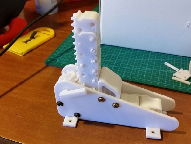


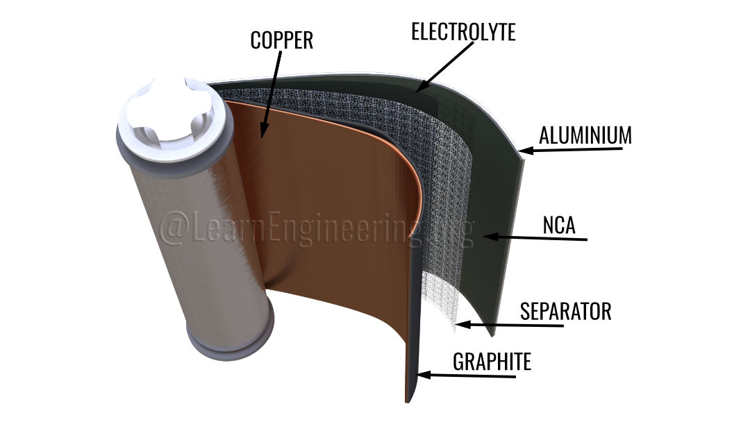

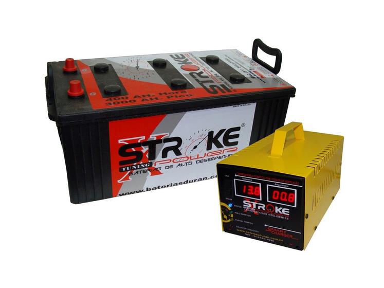

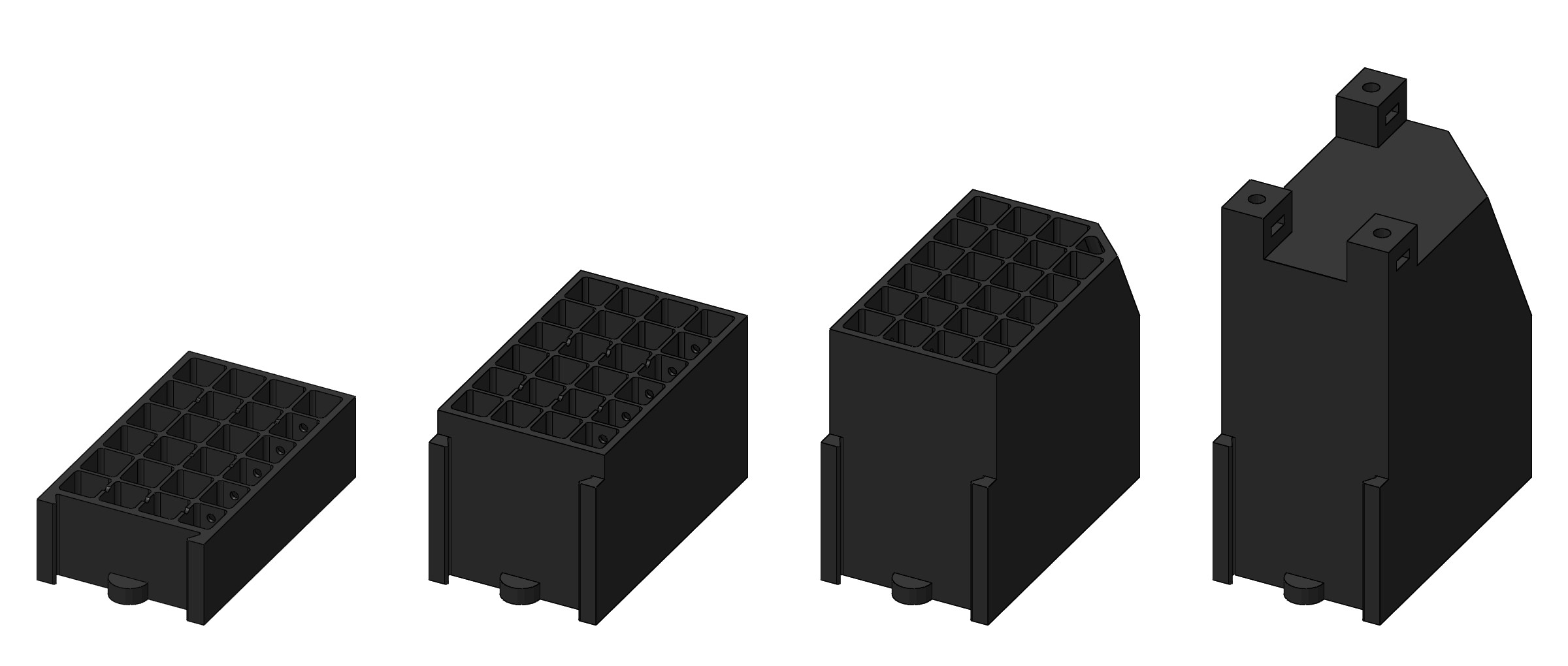
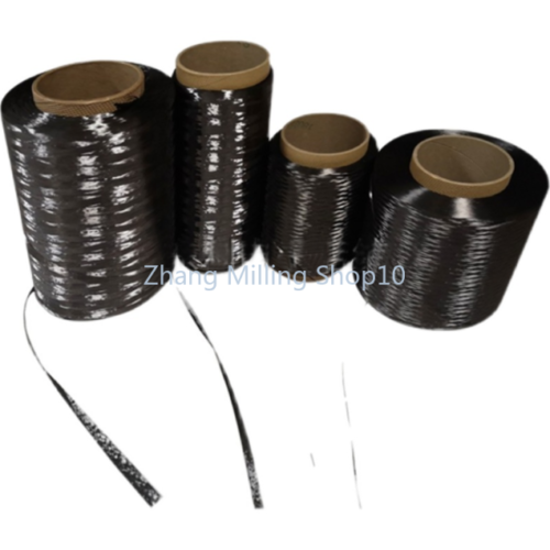


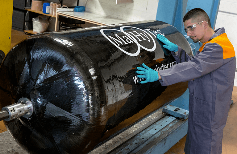


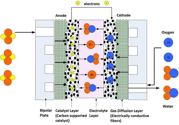
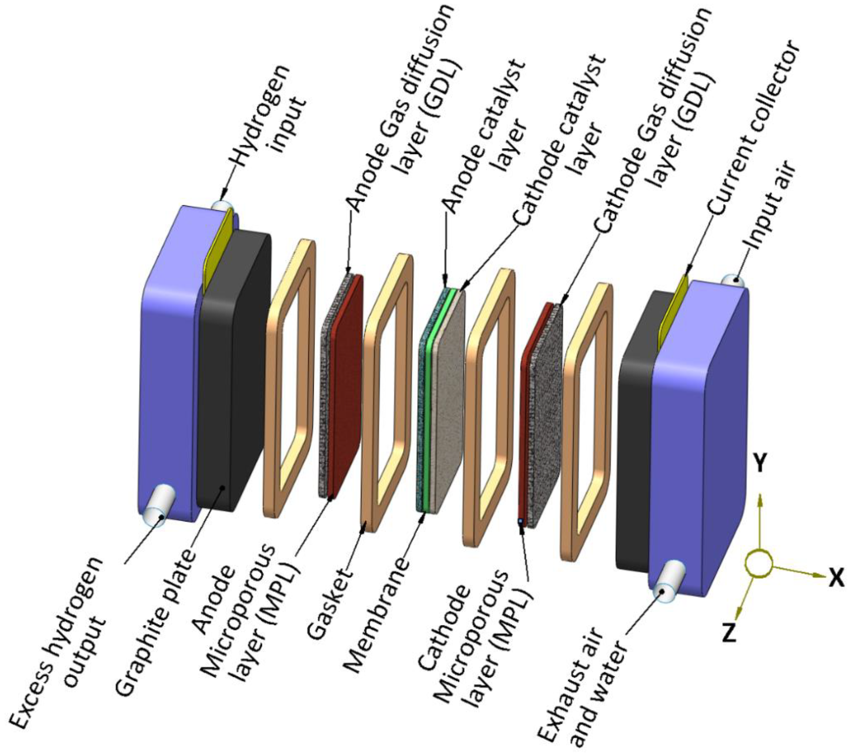

 The article: "