 doctek
(Here's the complete description - sorry for some redundancy.) There are many single chip bipolar stepper motor controllers. These can supply one to two amps and work great for most NEMA 17 and smaller motors. But I wanted to control a long NEMA 23 motor with 0.3 Ohm coil resistance. For comparison, a NEMA 17 with 1 Ohm resistance took over 1A from an a4988. Even NEMA 17s can cause a lot of heating! Larger motors are often controlled using the TB6600 or TB67S109. These controllers can handle 3 to 3.5A, but are a bipolar design and require large heat sinks. Trinamic offers the TMC5160A that uses external FETs and can handle 5 Amps easily. Since that's more than enough for the motors I have, that became my design goal.
There are various boards available using the TMC5160A. The TMC5160-EVAL is good for 4.7A, but costs $108. The smaller TMC5160-BOB is only good for 2.8A and costs $22. The TMC5160 SilentStepStick claims 3A and only costs $15. But the last two boards lack the necessary capacitors needed for reliable operation, and have no wiring connectors. My goal is to design a complete solution that can handle 5A safely and reliably, and not require a huge heat sink. The ease of use of the Trinamic controllers and configuration using SPI was very attractive. Although I'm currently using very few of the features, it's good to have options.
The design process is described in the data sheet, but there are a few details that are glossed over. The first one is the sizing of the gate resistors. The second is the sizing of the bulk capacitors. Software is left as an exercise for the user.
I will focus on my design and the software that worked. There was lots of experimenting and mis-steps to get here, lots of help from Joey Gross, the Maxim/Trinamic Tech Support Guy, and still lots to do. But it's time to share. The design seems to be working well enough to be useful. Perhaps what I did will inspire others to help wring out the design.
Circuit Design Details
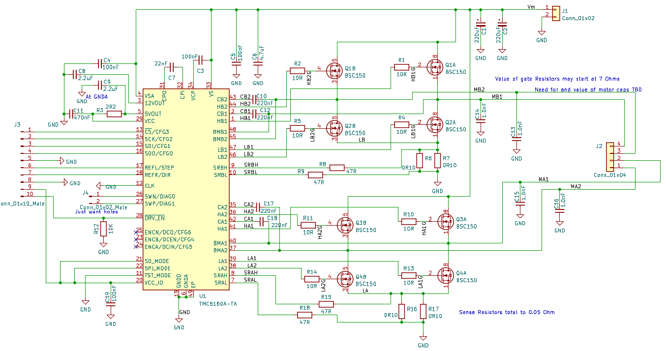
The design shown in the data sheet provided most of the guidance for creating this board. The limitation of 24V is due to my desire to avoid excessive heat generation in the Trinamic part. Since 24V was my design goal, I'm quite happy with this. However, my first efforts at bringing it up were less than successful. Partly this was due to lack of details about the software needed to configure the device, and partly because part selection could have been improved - but not really explained in the data sheet. Both these problems were resolved with crucial help from Joey at Maxim support. The software is discussed below. The hardware design notes follow. Start with the schematic. The KiCad files and a pdf of the schematic are in the Files Section.
| TMC5160A | TQFP package selection | It was available! | ||
| MOSFET Selection | BSC150N03LD, 30V, 20A, 12.5mOhm RdsON, Qg 10nC | Dual Package | Would have preferred 40V, but this was available | |
| C1, C2 | Vm Bulk Smoothing Capacitors | See discussion below | ||
| C3 | Charge Pump Voltage Capacitor | 100nF, 100 V | Sec. 29.5, Schematic | |
| C4 | Analog Supply Capacitor | 100nF, 100 V | Sec. 29.5, Schematic | |
| C5 | Vm Filter Capacitor | 100nF, 100 V | Sec. 29.5, Schematic | |
| C6 | Vm Filter Capacitor | 4.7uF, 100 V | Sec. 29.5, Schematic | |
| C7 | Charge Pump Capacitor | 22nF, 100V | Sec. 2.2, Pin 32 of TQFP | |
| C8 | 12V Out Capacitor | 2.2uF, 25V | Sec. 2.2, Pin 3 of TQFP & Sec. 29.5, Schematic | With Bootstrap capacitors of 220nF, 2.2uF was right. When Boostrap Caps were raised to 470nF, 4.7uF was used. |
| C9 | 5V Out Capacitor | 2.2uF, 25V | Sec. 2.2, Pin 5 of TQFP & Sec. 29.5, Schematic | Raised to 4.7uF at suggestion of Apps Engineer. |
Hardware Design Table continued (Trying to avoid the vengeance of the Table creator.)
| C10, C12, C17, C18 | Bootstrap Capacitors | 220nF, 25V | Fig. 3.1, Note at lower right - MOSFET Qg <20nC & Sec. 29.5, Schematic | Raised to 470nF at suggestion of Apps Engineer. |
| C13, C14. C15, C16 | Bridge Output Capacitors | 1.0 nF, 100V | Fig. 3.5, Note at lower right | |
| C19 | VCC_IO Capacitor | 100nF, 16V | 3.1, Note by VCC_IO | |
| R1, R2, R4, R5, R10, R11, R13, R14 | Gate Resistors | See discussion... |


 Paul Gould
 Marcos
 Jean-François Duval
There's only one. Find the Files area (above), then the file you want is T31_TMC5160_Test_AccelStepper2.ino.