 IoT-devices, LLC
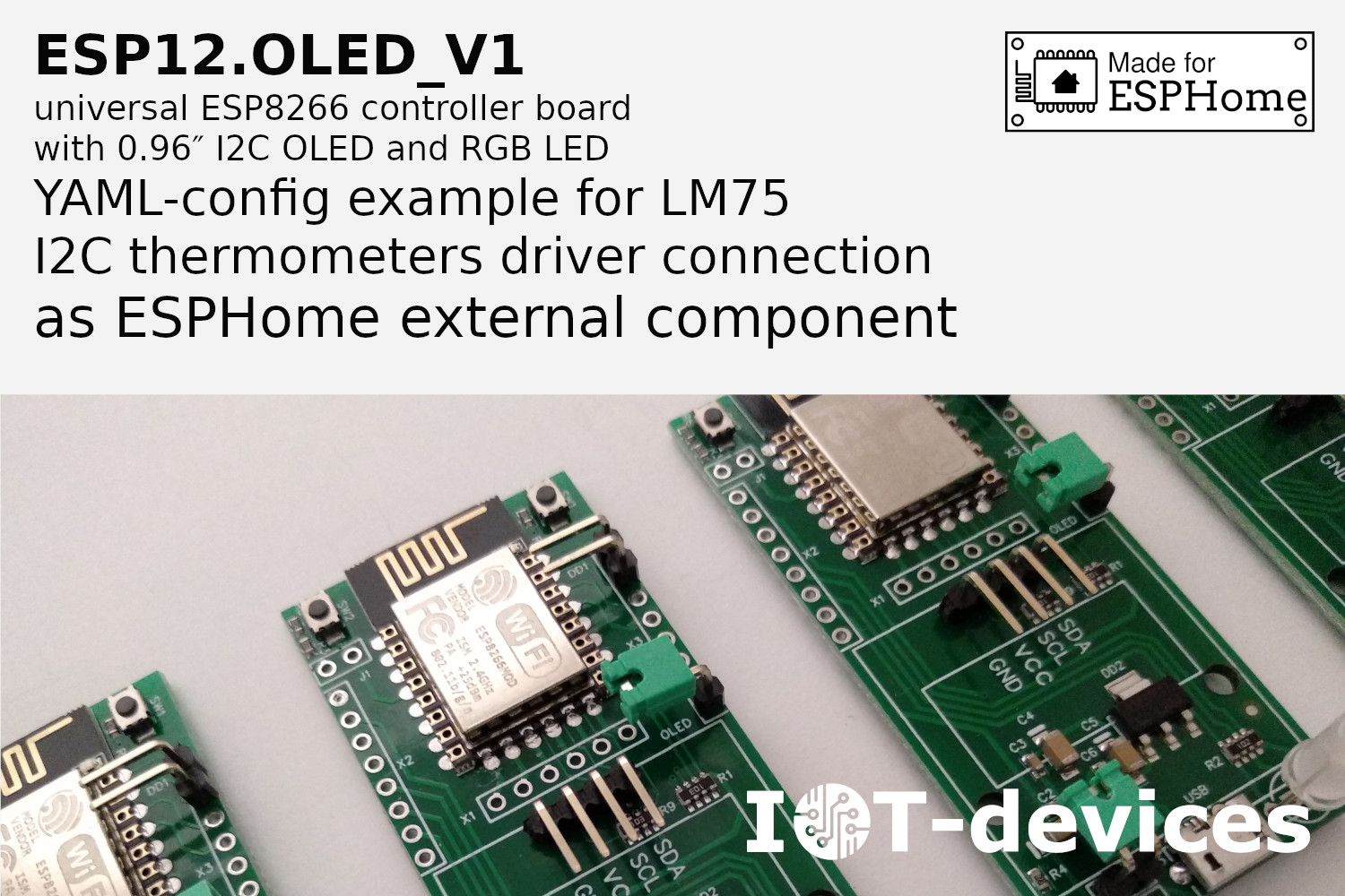
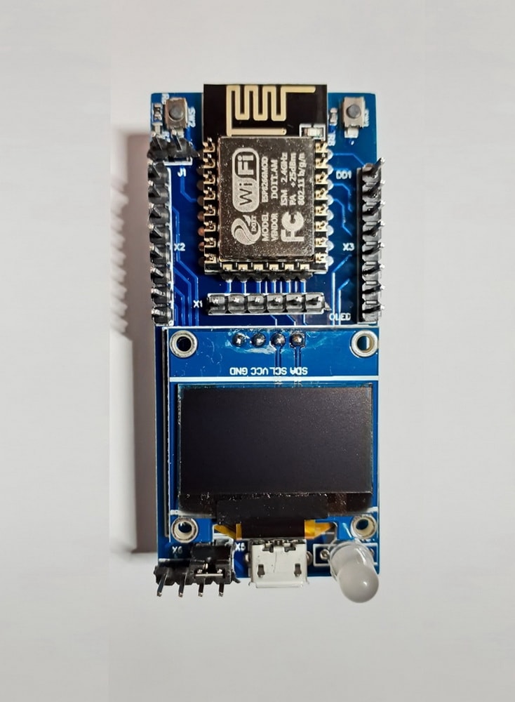
The development board has:
- PCB holes for GPIO pin-headers with step 2.54 mm
- ESP8266-12 MCU
- onboard SSD1306 128x64 monochrome 0.96" OLED I2C display
- Flash button
- Rst button
- RGB LED
- UART interface connection for testing and programming via terminal console.
The ESP12.OLED development board can be easily integrated into any 3rd - party systems with a power level of 3.3 or 5 Volts and with a logic level of 3.3 Volt.
The board has a built-in 3.3 Volt regulator. 4.5 to 6 Volt (5.6V maximum recommended). DC input power is supplied via micro-USB connector or VCC and GND.
The ESP8266-12E (F) module has the specifications provided by AI-Thinker.
All ports (I/O pins) of ESP8266-12E (F) are soldered out. GPIO headers of the development board are supplied separately. The step between the headers is 2.54 mm. The pin placement sequence is the same as the pin placement sequence on the ESP826612E (F).
Demonstration software (IoT-devices Test Tools) is pre-loaded on the ESP8266 module to quick-test and demonstrate main technical functionality of the board. This software starts in 10 seconds after power is applied.
User Manual on this software is available in a separate document. See link below.
Specifications and properties:
- MCU properties comply with ESP-12F Datasheet.
- To program the controller, connect ESP12.OLED via the UART connector to your computer using a UART-USB interface converter on the CP2102 chip or similar.
- Average current consumption of the controller without connecting additional devices and active Wi-Fi is about 80mA. In Deep Slep mode average current consumption - 10uA
- Current consumption with deactivated Wi-Fi no more than 10 mA.
- The maximum load level on the 3V3 board output for external elements of the system is 500 mA.
- Install j1 to activate "Deep Sleep Wake Up Circuit".
- Power supply mode selection:
- install X5 jumper for 5v power supply via uUSB or X6 pin;
- else uninstall X5 jumper to select 3v3 power supply via X6 pin.
- Dimensions 30x65x10 mm.
Comparison of ESP12.OLED development board and NodeMCU classic board
| ESP12.OLED | NodeMCU classic board | |
|---|---|---|
| Power Input Voltage Selector | 5V or 3V3 via jumper | None, 5V only |
| MCU Module | ESP8266-12F | ESP8266-12F |
| UART interface | Present, Tx/Rx pin-headers | Present, Tx/Rx pin-headers or via micro-USB |
| Micro-USB interface | Power only | Power and Data |
| Deep Sleep Wake Up Circuit | Ready-to-use, via jumper | None, manual wiring |
| RGB LED | Built-in, via 3 x GPIO | None |
| OLED Display | Built-in | None |
| ADC Voltage Divider & port | Built-in, up to 5.6V DC input | None, port only |
| Fixed I2C bus pins | Yes, GPIO5 SCL, GPIO4 SDA | Not determined |
| Full pin-map soldered out | pin-headers supplied | pin-headers soldered |
 FloppidyDingo
 Pallav Aggarwal
 Bruce Land
 Michel Kuenemann