Close
0%
0%

a Break Out Board for an eXtremely Small Proc.

NXP has released the LPC812 Cortex M0+ controller in an eXtremely Thin Small Package (XSON16) . Why not design a BOB for it ?

Similar projects worth following
This tiny 32 bit processor has 16 pins and measures only 2.5 X 3.2 X 0.5 mm. Its package is leadless and has a pitch of 0.4 mm. It is (should be) much less difficult to solder than a BGA (see my "currently failed "YoctoBob project here: https://hackaday.io/project/5827-yoctobob-a-bob-for-an-ultra-tiny-cortex-m0-proc).
Good news: The 0.4 mm pitch is compliant with Eurocircuit's pooling process (minimal clearances of 150 µ). Other good news: the chip is sold by Mouser (1,5 € X 10 pieces).

The complete part number of this microcontroller is: LPC812M101JTB16X.

Those who are not familiar with this family of microcontrollers should visit nxp here:
http://www.nxp.com and search for "Cortex".

few words about our champion:

  • System:
    • ARM Cortex-M0+ processor, running at frequencies of up to 30 MHz with single-cycle multiplier and fast single-cycle I/O port
    • ARM Cortex-M0+ built-in Nested Vectored Interrupt Controller (NVIC)
    • System tick timer
    • Serial Wire Debug (SWD) and JTAG boundary scan modes supported
    • Micro Trace Buffer (MTB) supported
  • Memory:
    • 16 kB on-chip flash programming memory
    • 4 kB SRAM
  • Boot ROM API support:
    • Boot loader
    • USART drivers
    • I²C drivers
    • Power profiles
    • Flash In-Application Programming (IAP) and In-System Programming (ISP)
  • Digital peripherals:
    • High-speed GPIO interface connected to the ARM Cortex-M0+ IO bus with 14 General Purpose I/O (GPIO) pins with configurable pull-up/pull-down resistors
    • GPIO interrupt generation capability with boolean pattern-matching feature on eight GPIO inputs
    • Switch matrix for flexible configuration of each I/O pin function
    • State Configurable Timer (SCT) with input and output functions (including capture and match) assigned to pins through the switch matrix
    • Multiple-channel multi-rate timer for repetitive interrupt generation at up to four programmable, fixed rates
    • Self Wake-up Timer (WKT) clocked from either the IRC or a low-power, low-frequency internal oscillator
    • CRC engine
    • Windowed Watchdog timer
  • Analog peripherals:
    • Comparator with external voltage reference with pin functions assigned or enabled through the switch matrix
  • Serial interfaces:
    • Three USART interfaces with pin functions assigned through the switch matrix
    • Two SPI controllers with pin functions assigned through the switch matrix
    • One I²C-bus interface with pin functions assigned through the switch matrix
  • Clock generation:
    • 12 MHz internal RC oscillator trimmed to 1 % accuracy that can optionally be used as a system clock
    • Crystal oscillator with an operating range of 1 MHz to 25 MHz
    • Programmable watchdog oscillator with a frequency range of 9.4 kHz to 2.3 MHz
    • 10 kHz low-power oscillator for the WKT
    • PLL allows CPU operation up to the maximum CPU rate without the need for a high-frequency crystal. May be run from the system oscillator, the external clock input CLKIN, or the internal RC oscillator
    • Clock output function with divider that can reflect the crystal oscillator, the main clock, the IRC, or the watchdog oscillator
  • Power control:
    • Integrated PMU (Power Management Unit) to minimize power consumption
    • Reduced power modes: Sleep mode, Deep-sleep mode, Power-down mode, and Deep power-down mode
    • Power-On Reset (POR)
    • Brownout detect
  • Unique device serial number for identification
  • Single power supply
  • Operating temperature range -40 °C to 105 °C
  • Available as XSON16 package


Board Schematic
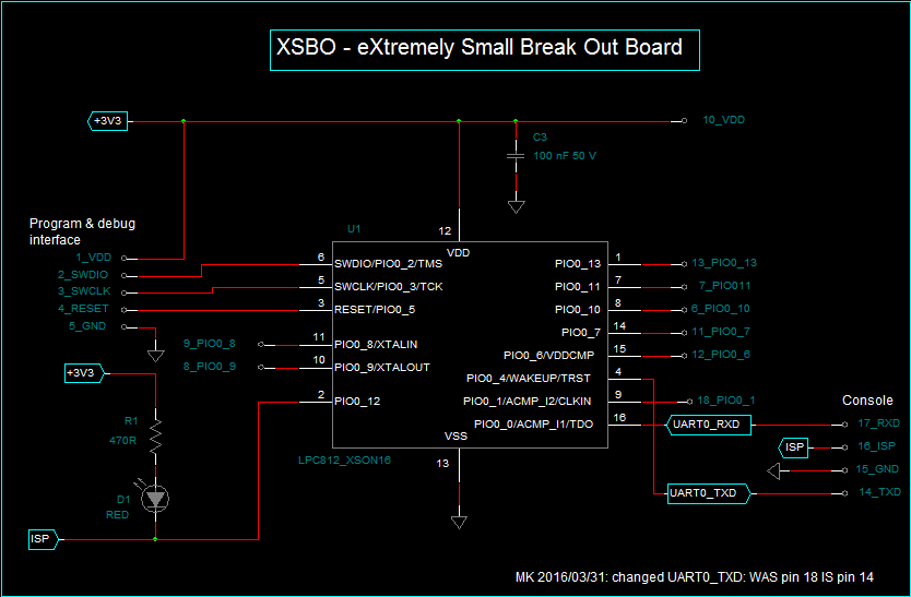
Board Pinout (Top View)

The pitch of the pins is 2.54 mm (100 mill).
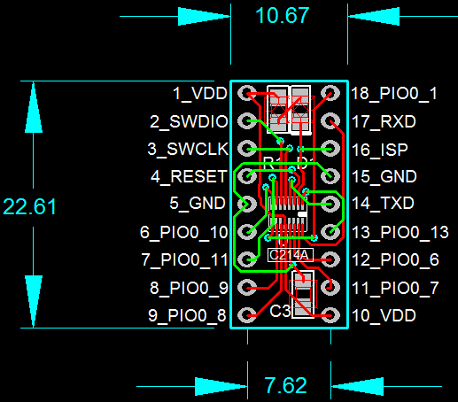


C214AA_XSBO_SCH.pdf

Schematics

Adobe Portable Document Format - 44.80 kB - 03/31/2016 at 11:20

Preview
Download

C214A_XSBO_PCB.pdf

PCB Drawing

Adobe Portable Document Format - 137.16 kB - 03/31/2016 at 11:20

Preview
Download

LPC81X_UM10601.pdf

LPC812 User Manual

Adobe Portable Document Format - 1.71 MB - 03/31/2016 at 11:08

Preview
Download

LPC81XM.pdf

LPC812 Data Sheet

Adobe Portable Document Format - 734.18 kB - 03/31/2016 at 11:07

Preview
Download

C214A_XSBO.GBR.ZIP

Gerber files - Compliant with Eurocircuits and PCBway pooling processes.

Zip Archive - 290.02 kB - 03/31/2016 at 11:06

Download

View all 7 files

  • 1 × LPC812M101JTB16X 32-bit ARM Cortex M0+ Microcontroller
  • 1 × Red LED - 0805
  • 1 × 470R resistor - 0805
  • 1 × 100 nF capacitor - 0805
  • 1 × XSBO PCB (Double sided)

  • Pinout updated on 2016/03/31

    Michel Kuenemann03/31/2016 at 11:02 0 comments

    I made a (small) pinout mistake:

    UART0_TXD was indicated on pin 18 of the module. This is false. UART0_TXD is affected to pin 14 in reality.

    This makes a small change in the pinout of the module. NO adverse impact on its functions.

    All the pictures and files have been update accordingly.

  • Tuesday 2016/03/22: mass production of seven XSBO boards ;-)

    Michel Kuenemann03/22/2016 at 13:48 0 comments

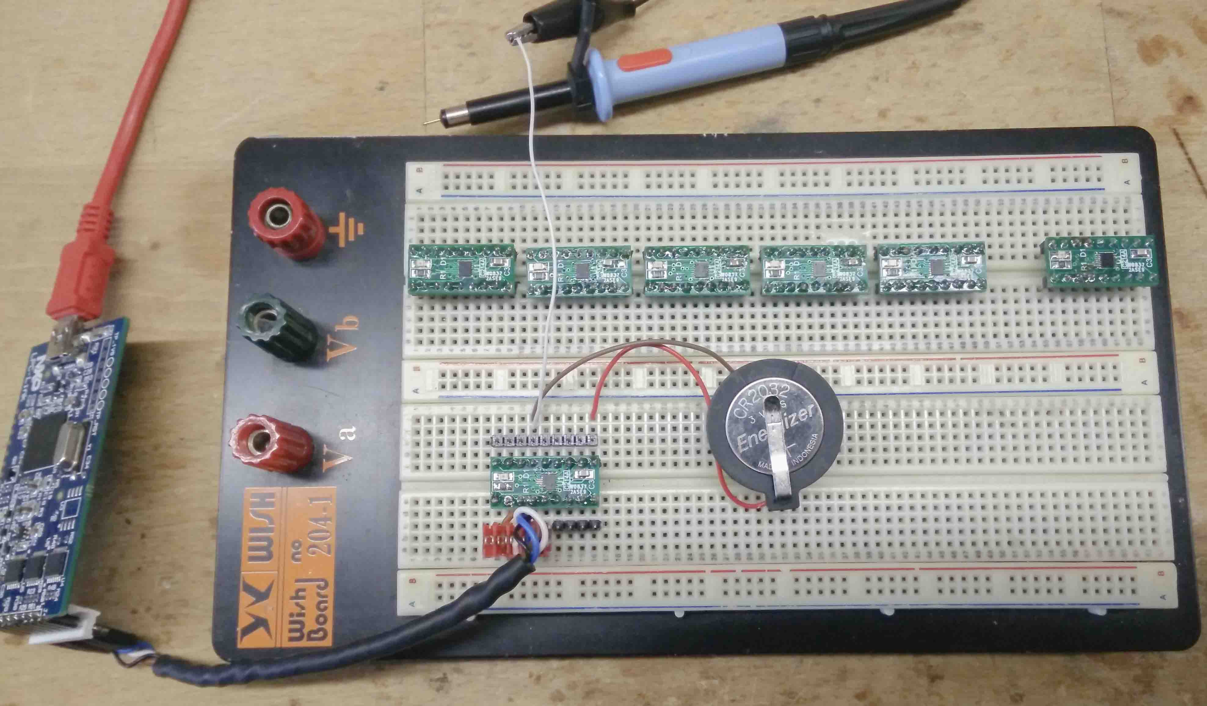
    This morning I have populated and "baked" 7 XSBO boards in my reflow oven. The operation was fully successful and all boards work perfectly.

    The picture shows the test software flashing process. This is done thanks to an LPClink module. During the test, the board is supplied bya CR2032 coin battery (3 Volts).

    Each I/O port is then checked with the oscilloscope probe.

    The 6 boards of the upper row have already been flashed and tested OK.

  • PCBs received, first board populated & tested: SUCCESS !

    Michel Kuenemann03/21/2016 at 14:17 0 comments

    have received the boards (10 of them) from china this morning (2016/03/21) and I have immediately populated a board - just to see...

    I am not equipped with reflow oven at my office, so I have made an attempt with a regular (big 80 Watt) Weller soldering iron :-).

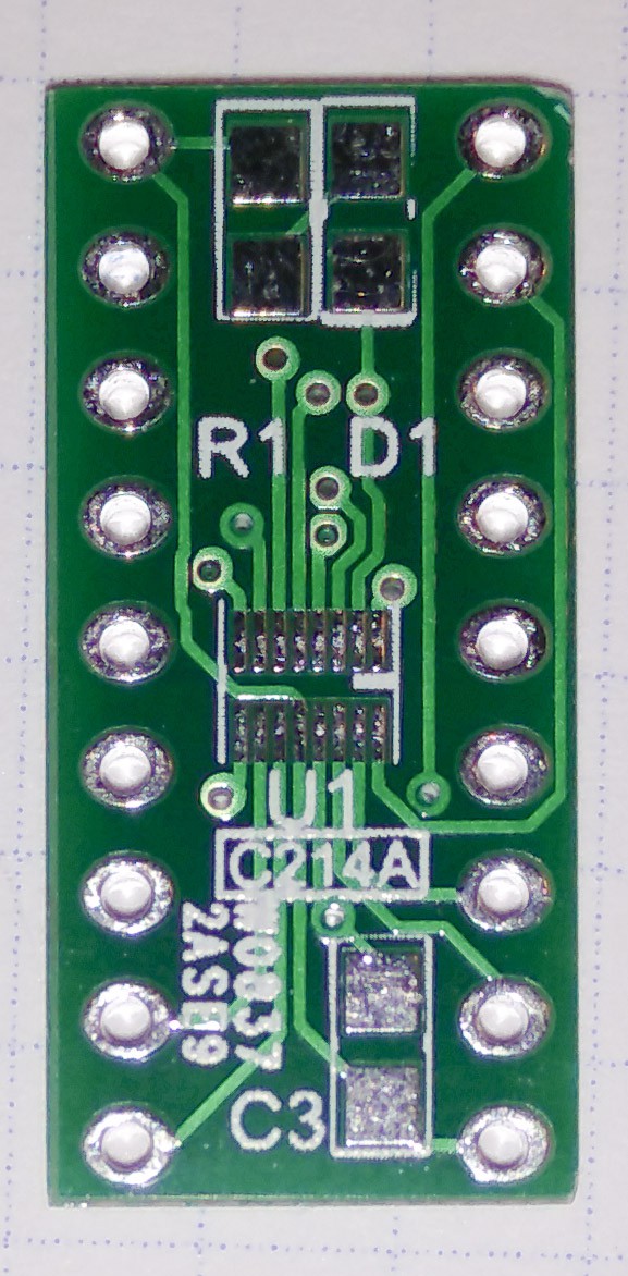
    Bare PCB


    The overall quality of the PCB seems OK.

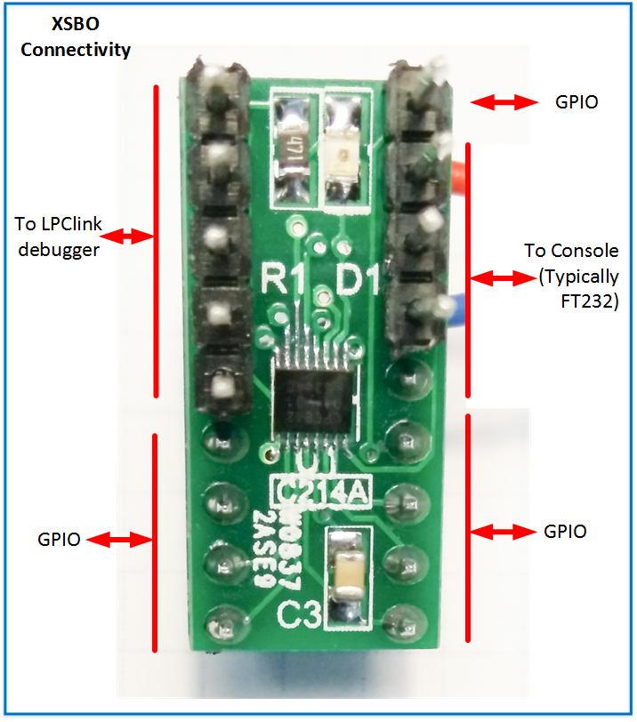
    First board populated

    There are only four electronic components on the board: an LED, a resistor, a capacitor and the microcontroller.

    The header on the left is to be connected to an LPClink board to flash the device. The 4 pins on the right are for a console.

    After the classic continuity tests, I flashed a basic blinky that I had prepared for this purpose.

    After a few hesitations, I managed to flash the programm and it worked immediately. So the board is at least "flashable". I have not yet tested all the ports, but I am confident.

    Conclusion: it is possible to solder 0.4 mm pitch DFNs with a regular soldering iron (without frying them).

  • PCB's ordered on 2016/03/15

    Michel Kuenemann03/15/2016 at 12:03 0 comments

    The layout is finished and I will order 10 PCB's at pcbway.

    Order has been passed this afternoon - The boards should be delivered by the begining of next week. Wait and see...

  • Microcontrollers received on 2016/03/14

    Michel Kuenemann03/14/2016 at 13:59 0 comments

    2016/03/11: 20 parts ordered at Mouser.

    Mouser have been very fast. Components ordered on friday and received today, monday.

    The picture in the galery shows the LPC812 (rectangular XSON16 package) and the LPC1102UK (square BGA package) side by side. The squares printed on the paper measure 5 X 5 mm ( 1/5 X 1/5 inch).

View all 5 project logs

Enjoy this project?

Share

Discussions

Simon wrote 03/23/2016 at 19:16 point

Hi Michel, really nice and tiny project in the similar climate like mine :)

https://hackaday.io/project/10412-awesome-pcb-breakout-board-for-most-popular-smd

Cheer Simon.

  Are you sure? yes | no

Michel Kuenemann wrote 03/24/2016 at 12:09 point

Hello Simon,

Thanks a lot for the message. Your BOB is great too.

Regards - Michel

  Are you sure? yes | no

berryelectronics wrote 03/16/2016 at 07:36 point

man, that thing is really tiny. on the image it looks so big but compared to the 0805 passives, wow! Good job!

  Are you sure? yes | no

Michel Kuenemann wrote 03/16/2016 at 07:49 point

Hello,

Yes the processor is a little bigger than two 0805 components. BTW I will put a photo showing that in the gallery. 

I hope I will have no soldering issues... I am used to soldering 0.5 mm pitch QFNs and I really like this kind of packages. 0.4 mm pitch should be OK as well.

Thanks a lot for the skull.

Grüsse,

Michel

  Are you sure? yes | no

Michel Kuenemann wrote 03/15/2016 at 12:10 point

Hello Gilles,

Thank you ! PCBway are currently checking the gerber files. This processor is really cool. It only lacks of analog inputs... Do not hesistate to give a skull, or a like !

Michel

  Are you sure? yes | no

Gilles KREBS wrote 03/15/2016 at 12:05 point

Hi Michel, it looks great! This LPC812 is impressively tiny!

  Are you sure? yes | no

Similar Projects

Does this project spark your interest?

Become a member to follow this project and never miss any updates