0%
0%
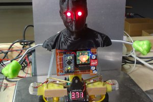
Line Follower Robot - King of Maze
Automated item delivery through shortest available path - Useful in industries for pick and drop cases - no requirement of ROS.
Become a Hackaday.io member
Already have an account? Log in.
Just one more thing
To make the experience fit your profile, pick a username and tell us what interests you.
Pick an awesome username
hackaday.io/
Your profile's URL: hackaday.io/username. Max 25 alphanumeric characters.
Pick a few interests
Projects that share your interests
People that share your interests
 Arno Munukka
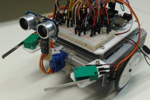
 Vinícius Jean Ferreira