Hulk
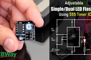
HulkWanted to generate a LED fading effect (fade-in and fade-out) for my upcoming video tutorial using the 555 timer IC.
I already have a video where I used LM358 Dual Operational Amplifier IC and another one with Arduino to generate the LED fading effect.
YouTube, is full of video showing how to generate the fading effect using 555 timer IC. However, none of them produce a true fading effect.
Some just fades-in but never fades-out. And there is literally no explanation of how they are generating the fading effect other than just showing how to assemble the components.
In this tutorial, I am going to show you guys how to create a true LED fading effect using the 555 timer IC. I will also explain how the circuit works and how changing components change the fading effect of the LEDs.
Components Required
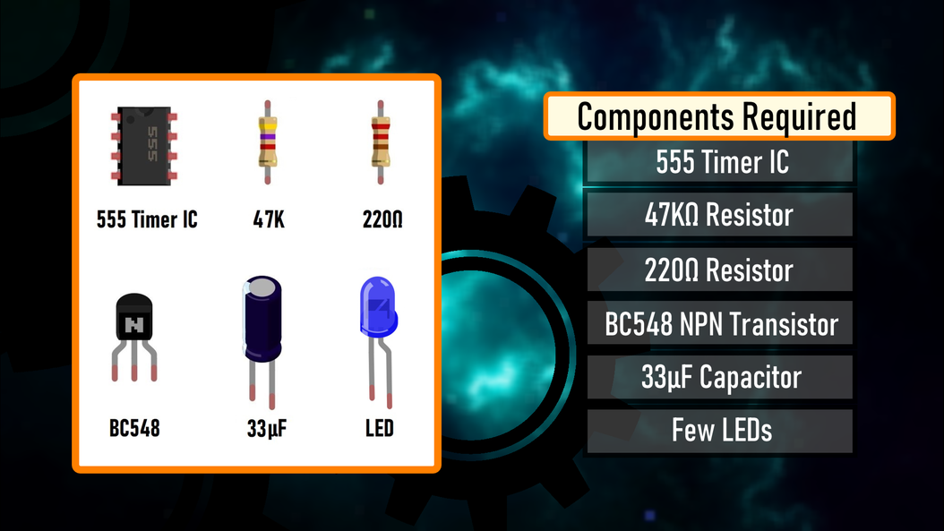
- 1 x 555 Timer IC
- 1 x 47KΩ Resistor
- 1 x 220Ω Resistor
- 1 x BC548 NPN Transistor
- 1 x 33µF Capacitor, and
- 1 x Few Blue LEDs
Circuit Diagram

The heart of this circuit is the 555 timer IC.
Pin No.1 of the IC is connected to GND.
By connecting Pin 2 and 6 of the 555 timer IC, we put the IC in astable mode. In astable mode, the 555 timer IC acts as an oscillator (re-triggering itself) generating square waves [PWM Signals] from the output Pin no. 3.
3 other components connect to this junction.
1st one is the 33µF capacitor. The positive pin of the capacitor connects to the junction and the negative pin is connected to the GND.
2nd one is the 47KΩ resistor. One of its legs connects to the junction and the other leg connects to the Output pin, Pin No.3 of the IC.
3rd one is the Base of the BC548 NPN transistor. The collector of the transistor along with Pin 8 and 4 of the IC connects to the +ve terminal. of the battery. The LED along with its current limiting resistor is connected to the Emitter of the transistor.
That's it as simple as that.
Alright, now I am going to demonstrate how this circuit works with the help of an animation.
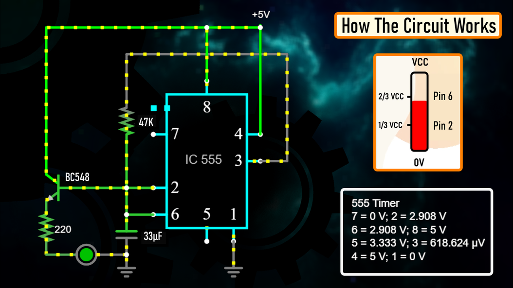
How The Circuit Works

- When Pin 2 of the IC detects voltage LESS than 1/3rd of the supply voltage, it turns ON the output on Pin 3.
- And, when Pin 6 detects voltage MORE than 2/3rds of the supply voltage, it turns OFF the output.

This is how the trigger pin (Pin2) and the
threshold pin (Pin6) of the 555 timer IC sense voltages and controls the output at Pin 3.

- The Capacitor attached to the circuit will be in a discharged state immediately after firing up the circuit.
- So, the voltage at Pin 2 will be 0v which is less than 1/3rds of the supply voltage, this will turn ON the output on Pin 3.
- Since Pin 3 is looped back to Pin 2, it will start charging the Capacitor via the 47KΩ resistor.
- At the same time the base current of the transistor also increases causing the LED to slowly "fade-in".
- Once the voltage across the capacitor crosses 2/3rds of the supply voltage, Pin 6 turns OFF the output.
- This causes the capacitor to slowly discharge causing the base current to fall and hence the LED starts "fading-out".
- Once the voltage across the capacitor falls below 1/3rd of the supply voltage, Pin 2 turns ON the output, and the above cycle continues.
You can hook up a multimeter to the circuit to measure the charging and discharging of the capacitor.
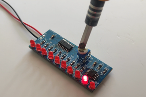
Breadboard Demo

So, here is a quick demo on a breadboard.
In the current setup I have a 33µF Capacitor and a Blue LED on the breadboard.
Replacing the 33µF Capacitor with a 100µF Capacitor makes the LED fade in-and-out slower as the 100µF capacitor charges and discharges slower than 33µF Capacitor.
Also by replacing the "Blue LED" with a "Red LED", we can make the LED to stay "on" longer than the blue one with the same value of capacitor. This is because the "Forward Voltage" (Vf) of the Blue LED is higher than that of the Red LED.
"Forward voltage" is the minimum amount of voltage that is required to allow an electrical component to turn on.
The red, green...

 John Loeffler