Neil Lambeth
Here are the features I wanted to include on the board:
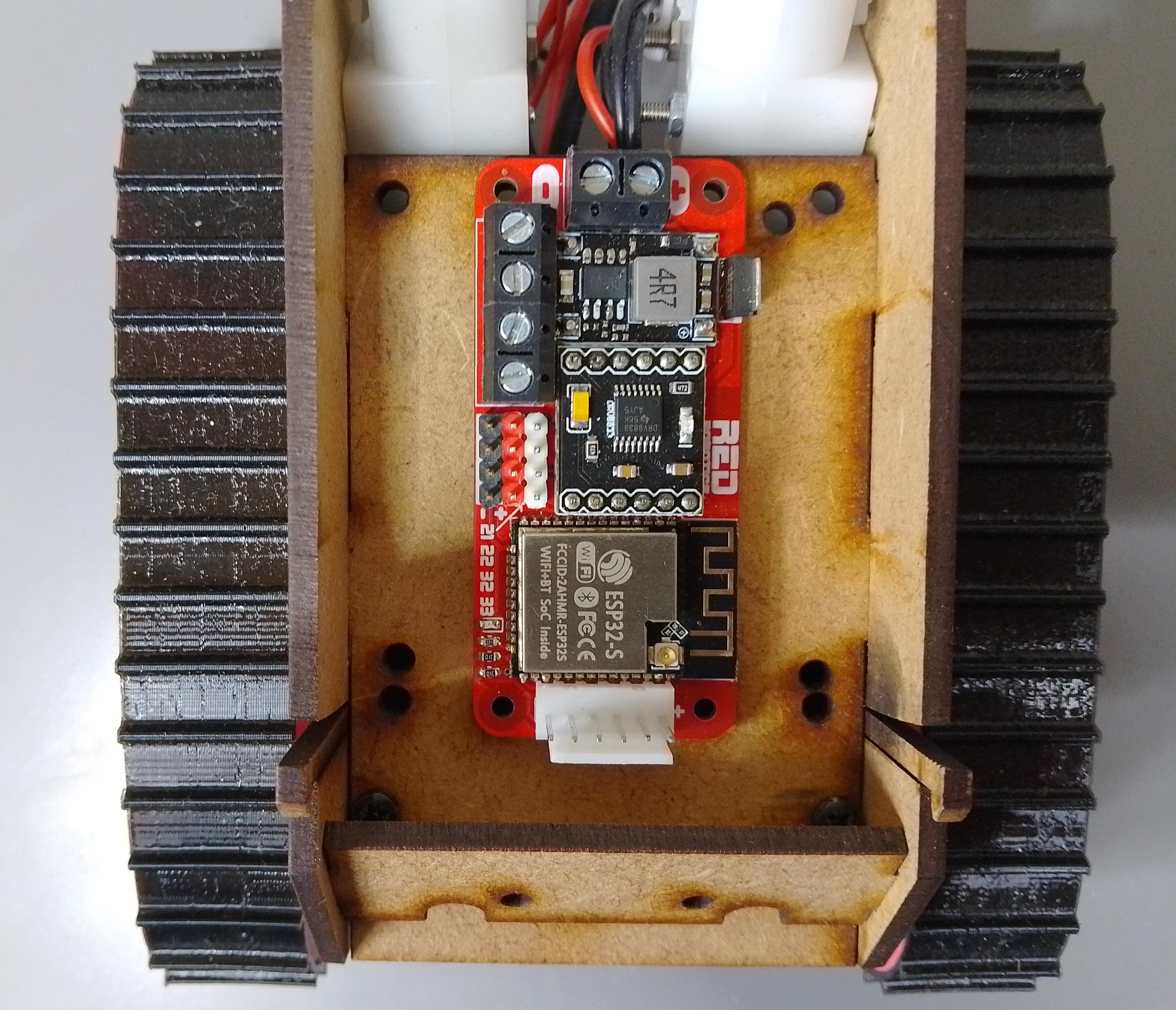
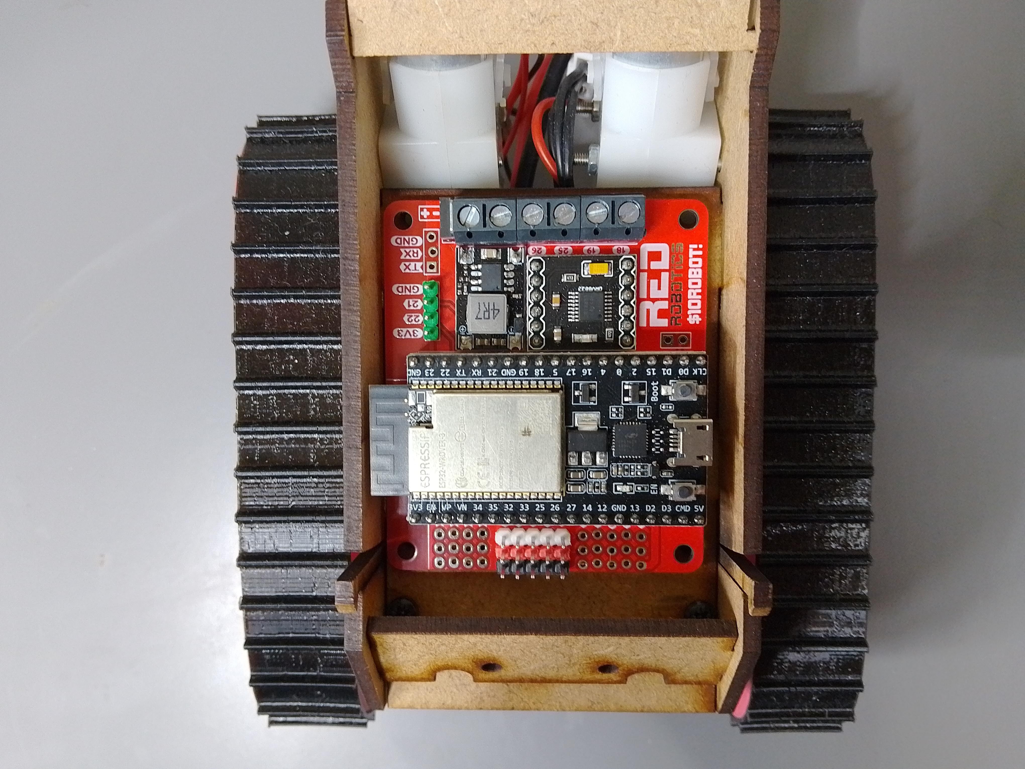
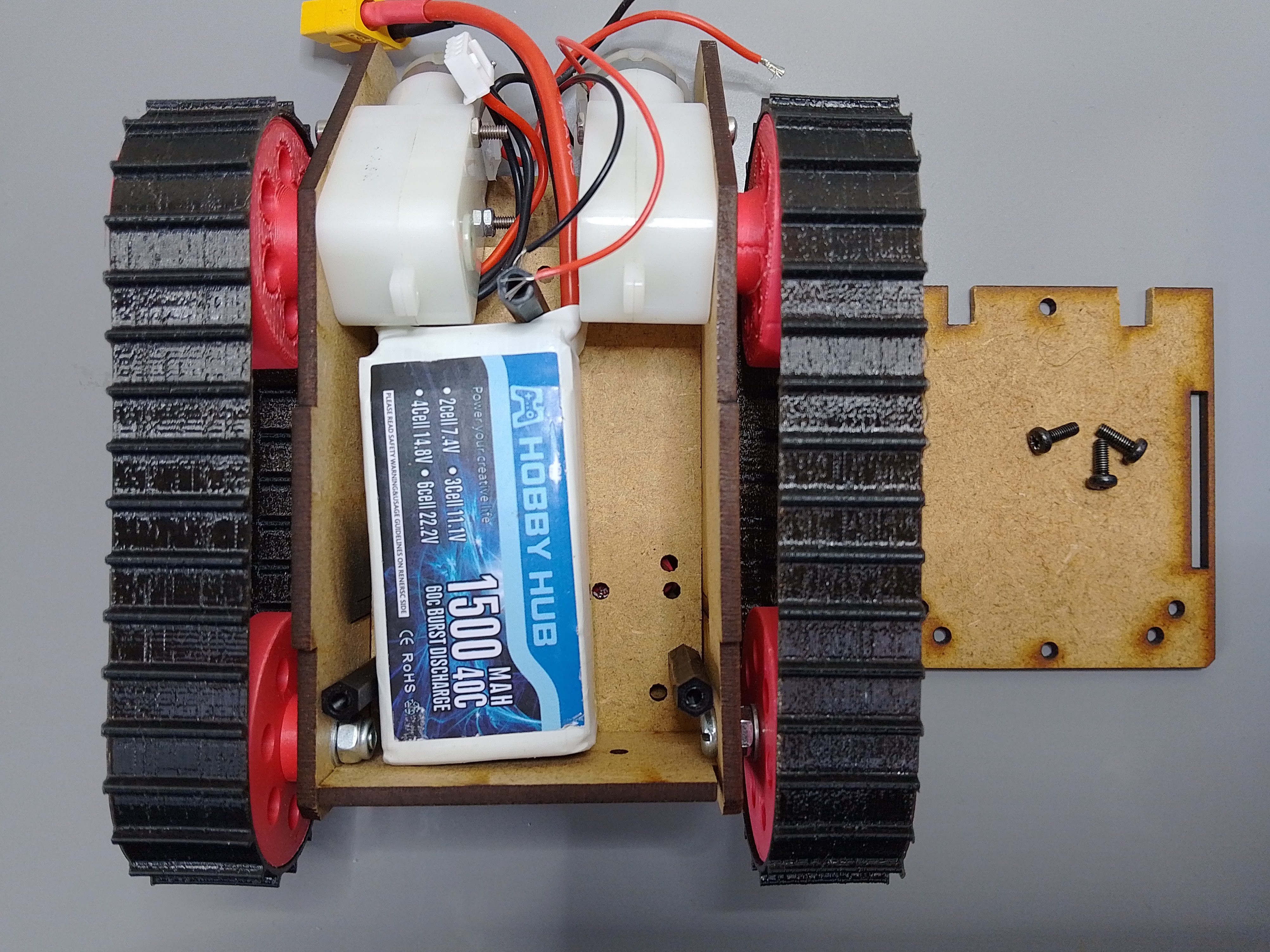
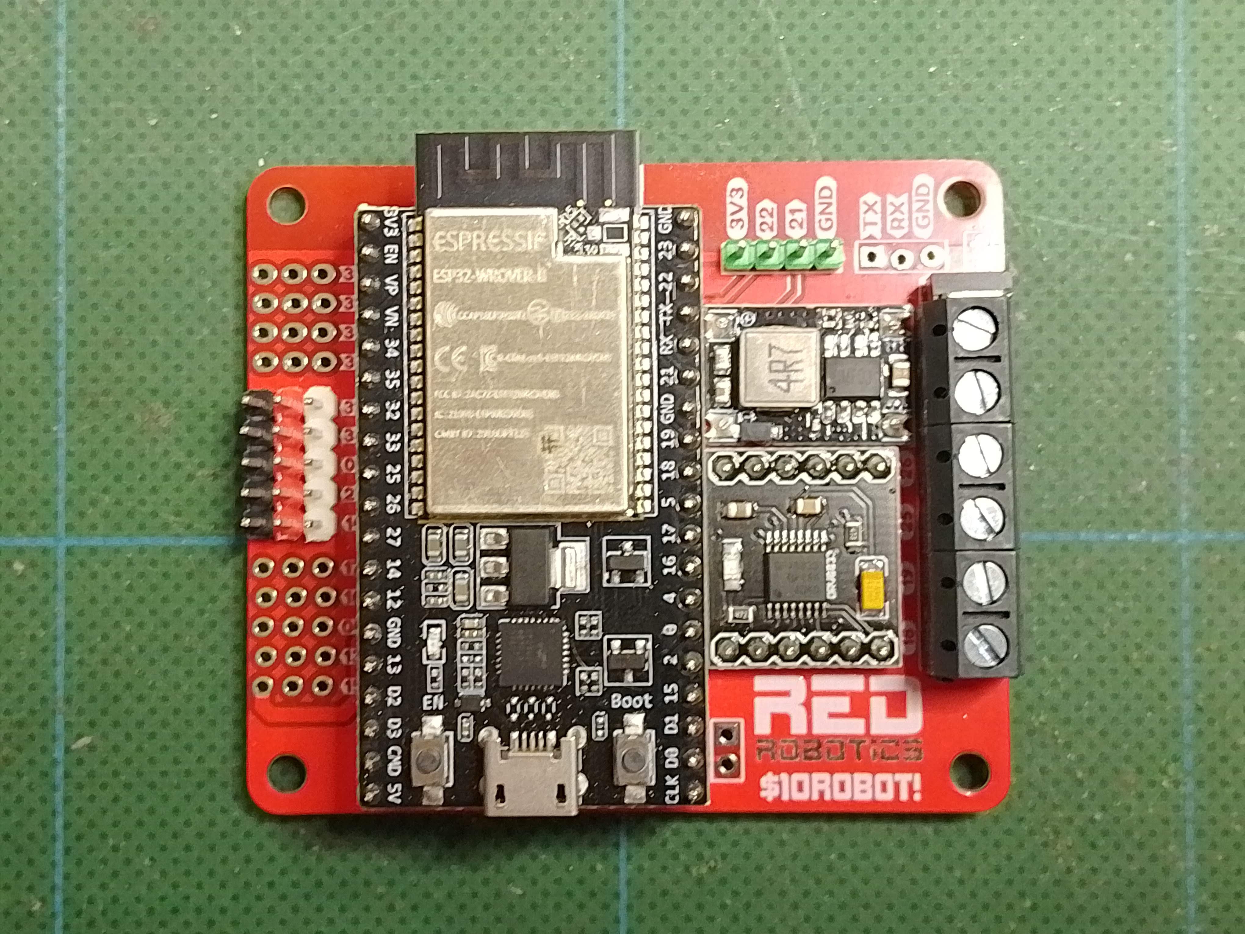
1. Dual H-Bridge – to drive 2 DC cheap TT motors, so nothing too fancy.
2. DC/DC converter – with an input voltage range of 6-12V, so you can use different types of batteries.
3. Reverse polarity protection – the students are definitely going to plug the battery in the wrong way around!
4.Enough spare input/output pins to drive a few servos or read a few sensors etc...
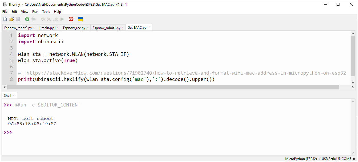
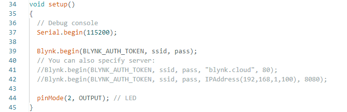
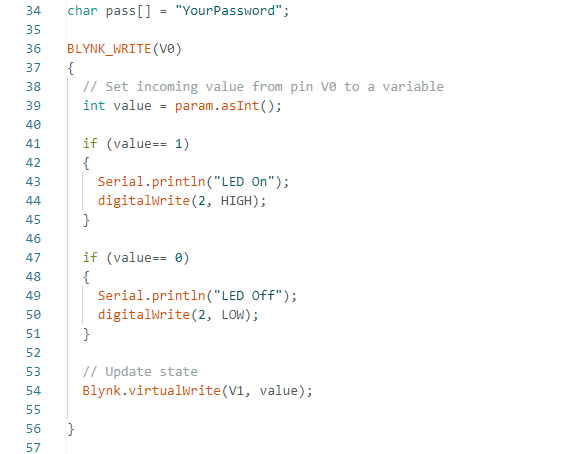
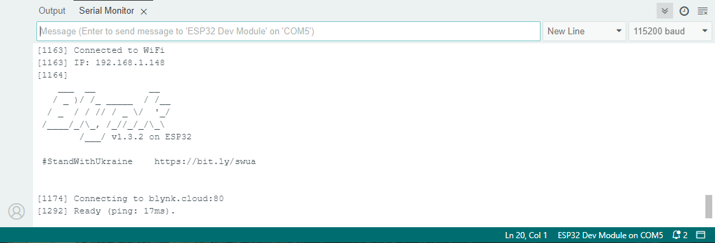
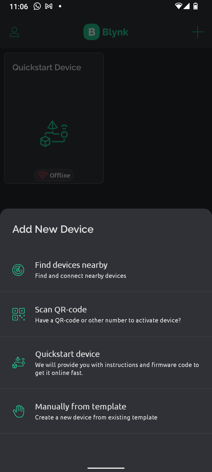
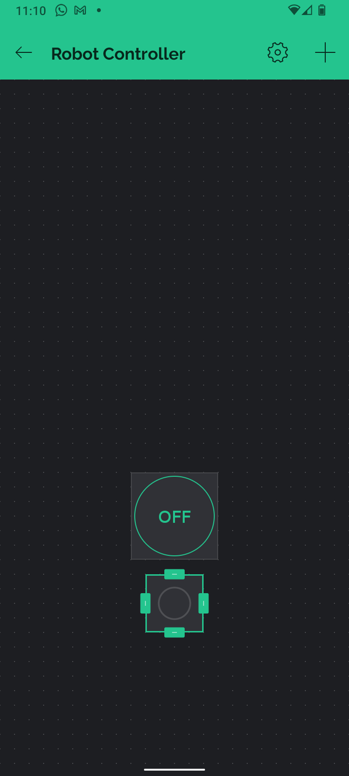
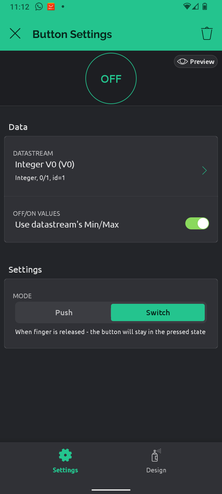
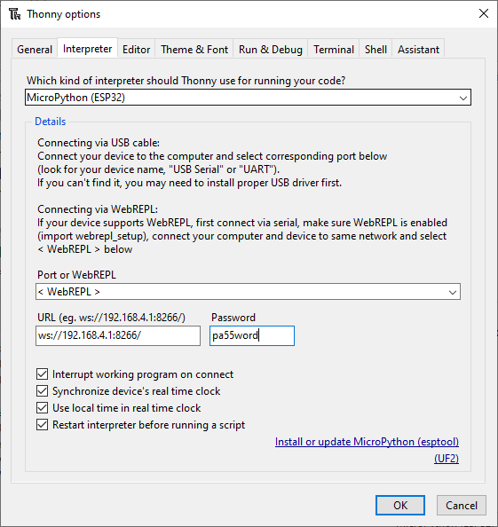
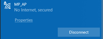
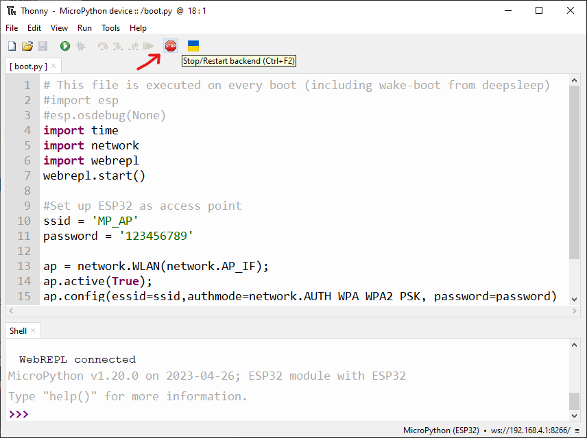
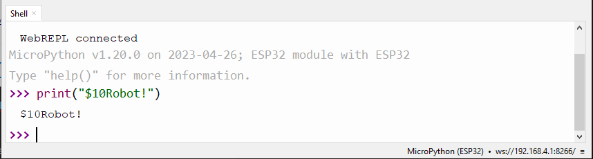
5. A micro controller with built in wireless communication. Preferably programmable in Micro/Circuit Python. Controllable from a mobile phone or website, so you don't need a physical controller to get started. But also with bluetooth, to connect to Playstation controllers, as we already use these for our other robots.
6. Cheap!
Nice, but not essential:
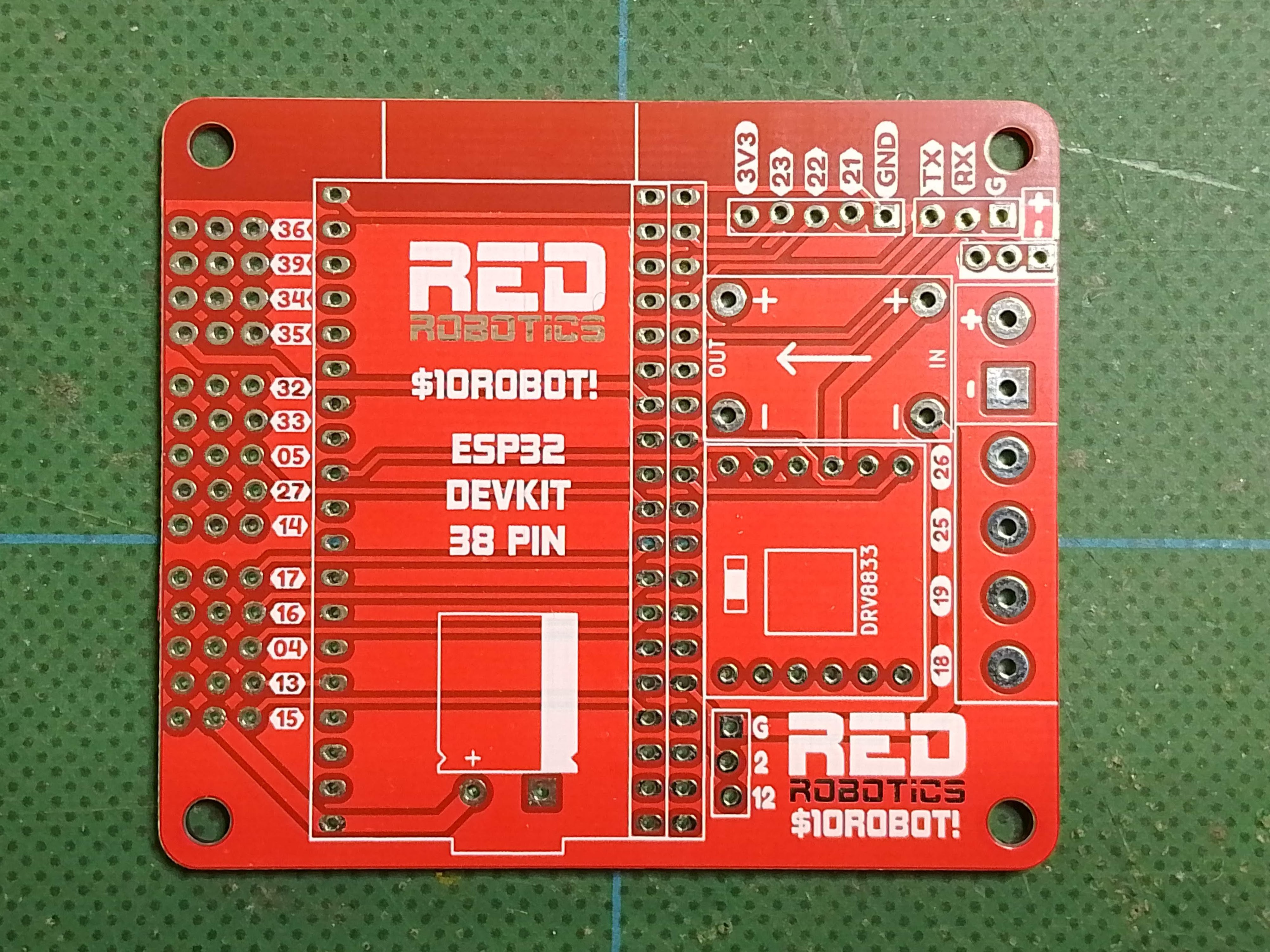
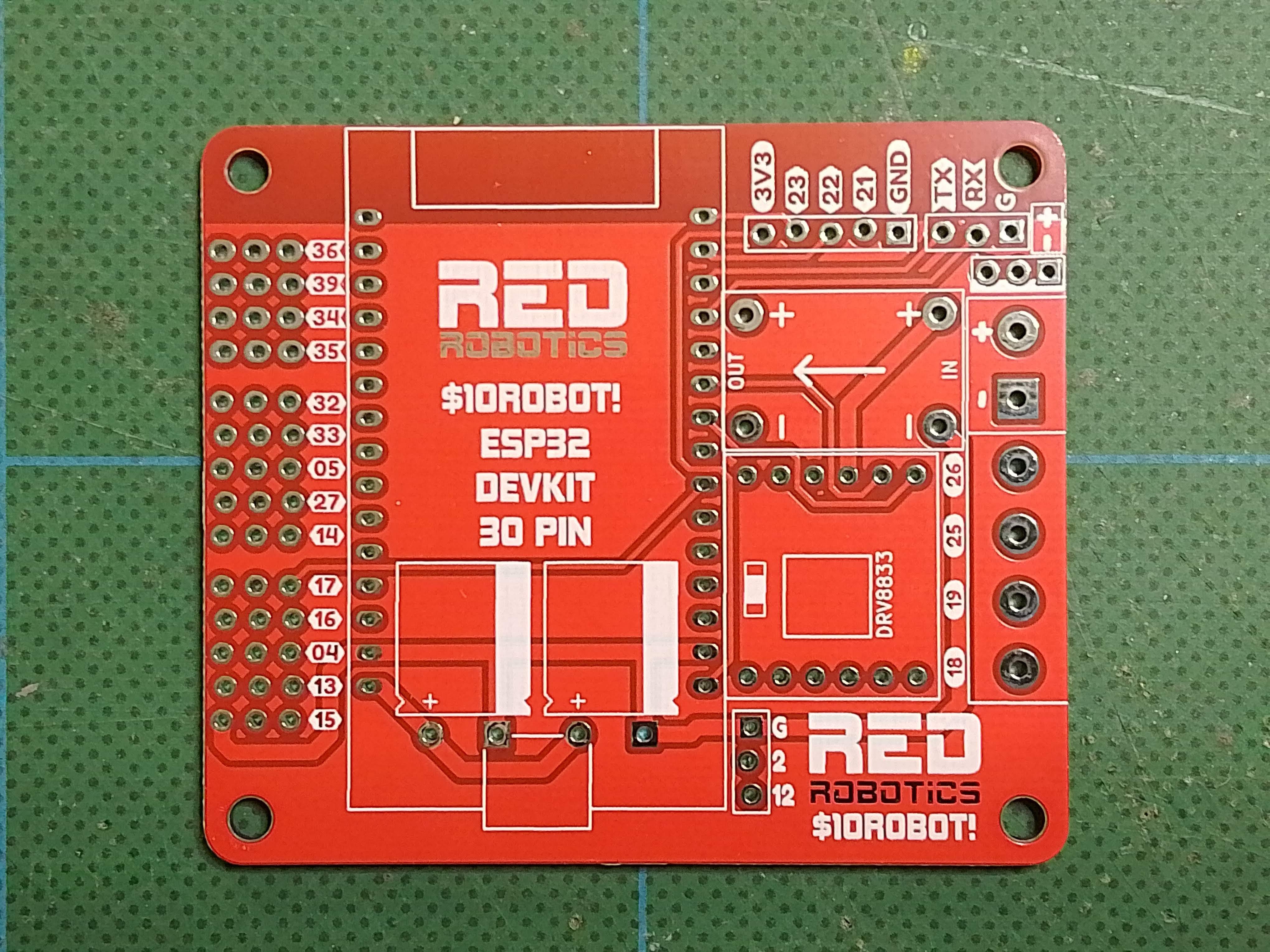
7. Through hole components – I want the students to assemble the boards themselves, so they can learn to solder, and have a better understanding of what the different parts on the board do.
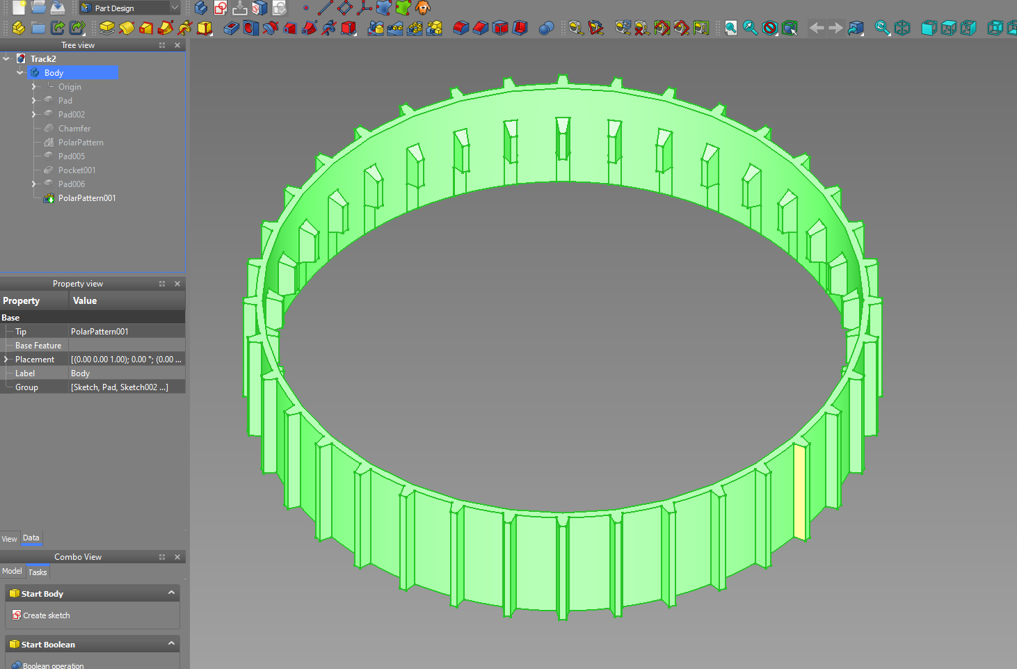
8. Raspberry Pi Zero sized – so it can replace the PI Zero's in our existing robots.
This project was started back in 2022 when electronic components were still hard to get hold of. So I looked around in my parts box so see if there was anything I could use and believe it or not, I found a load of dual H-bridge modules, DC-DC converters and micro controllers.
Having a quick check on AliExpress I got an idea of the costs:
2 x Yellow TT motors = $2.00
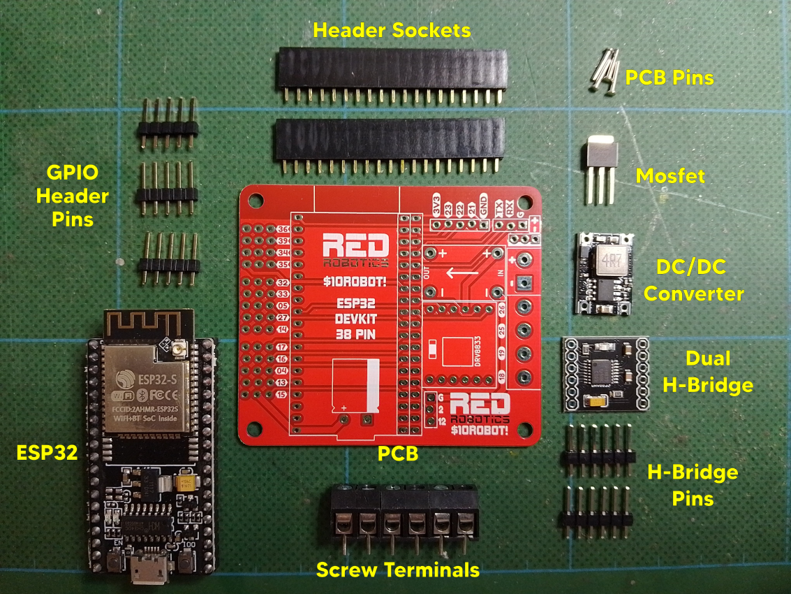
DC/DC Converter = $0.45
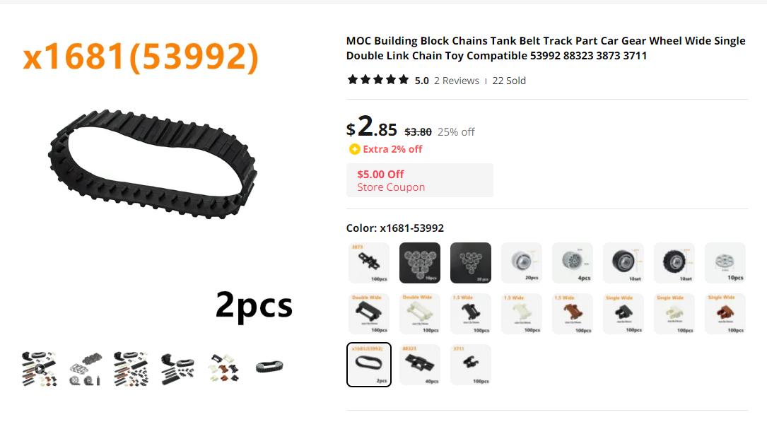
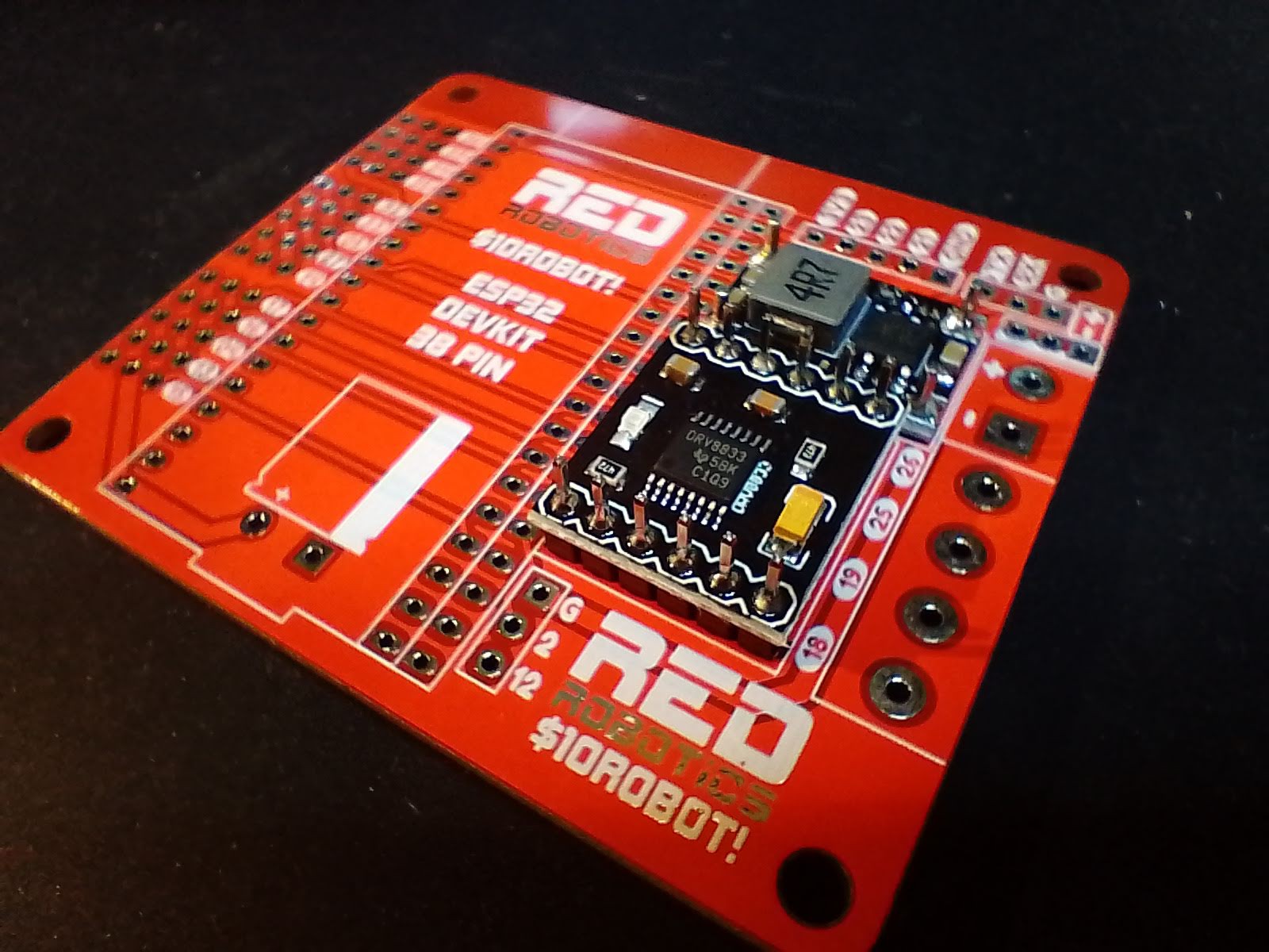
Dual H-Bridge Module = $0.50
MOSFET = $0.45
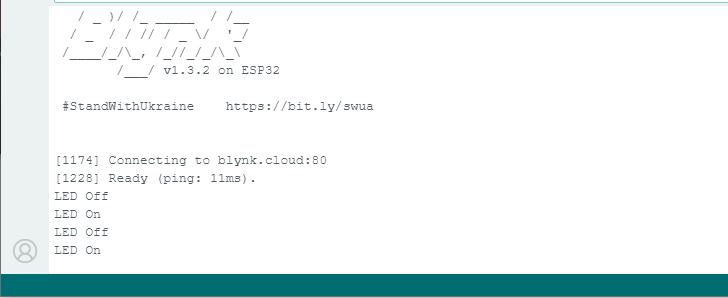
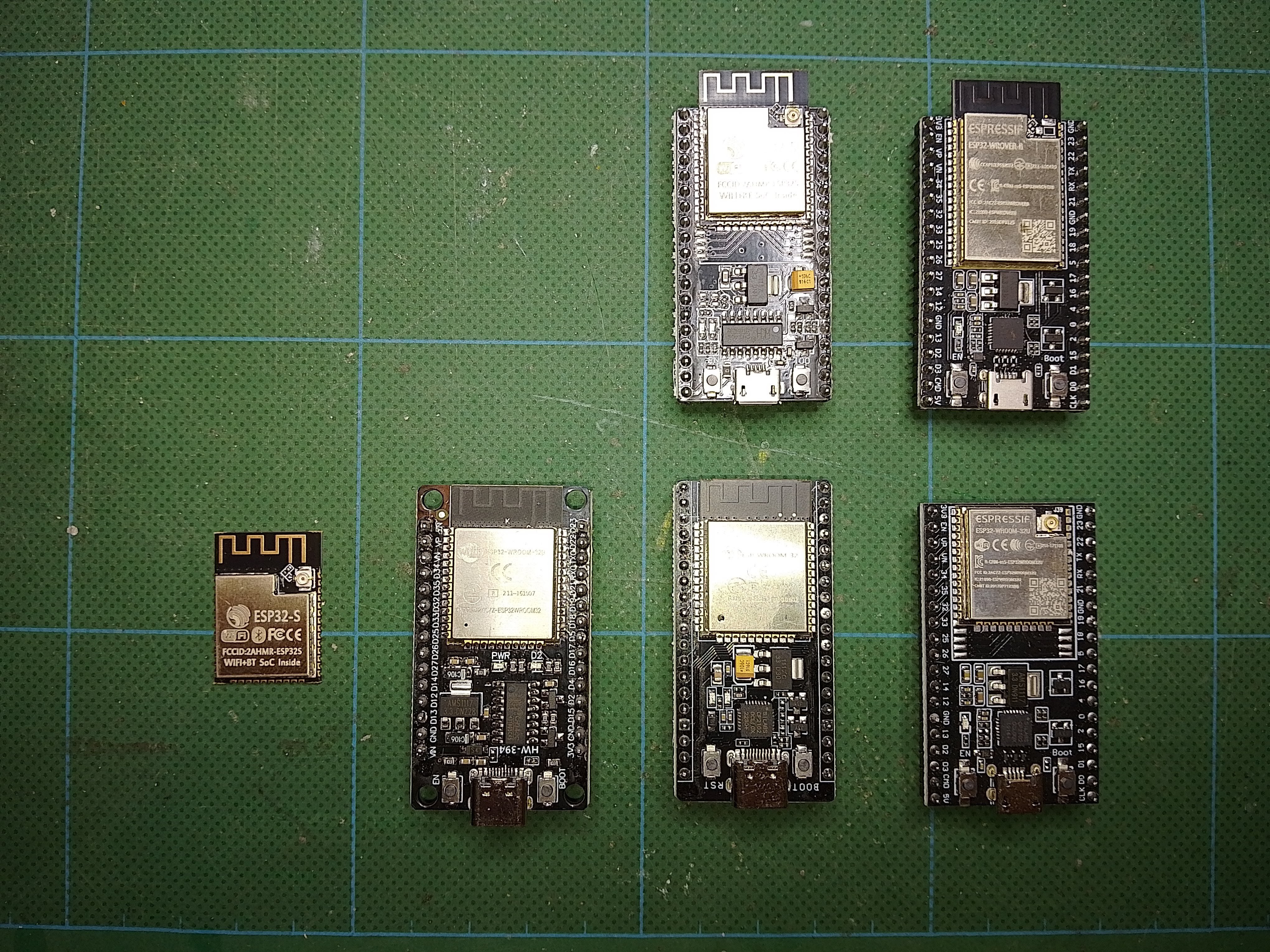
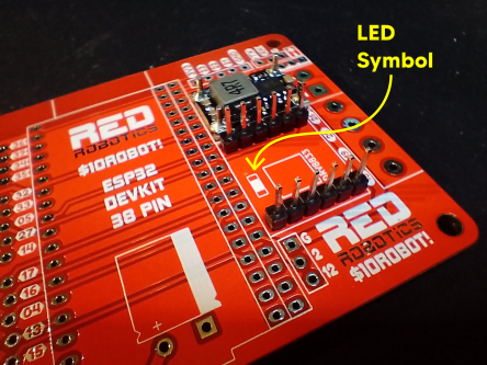
ESP32 = $3.00
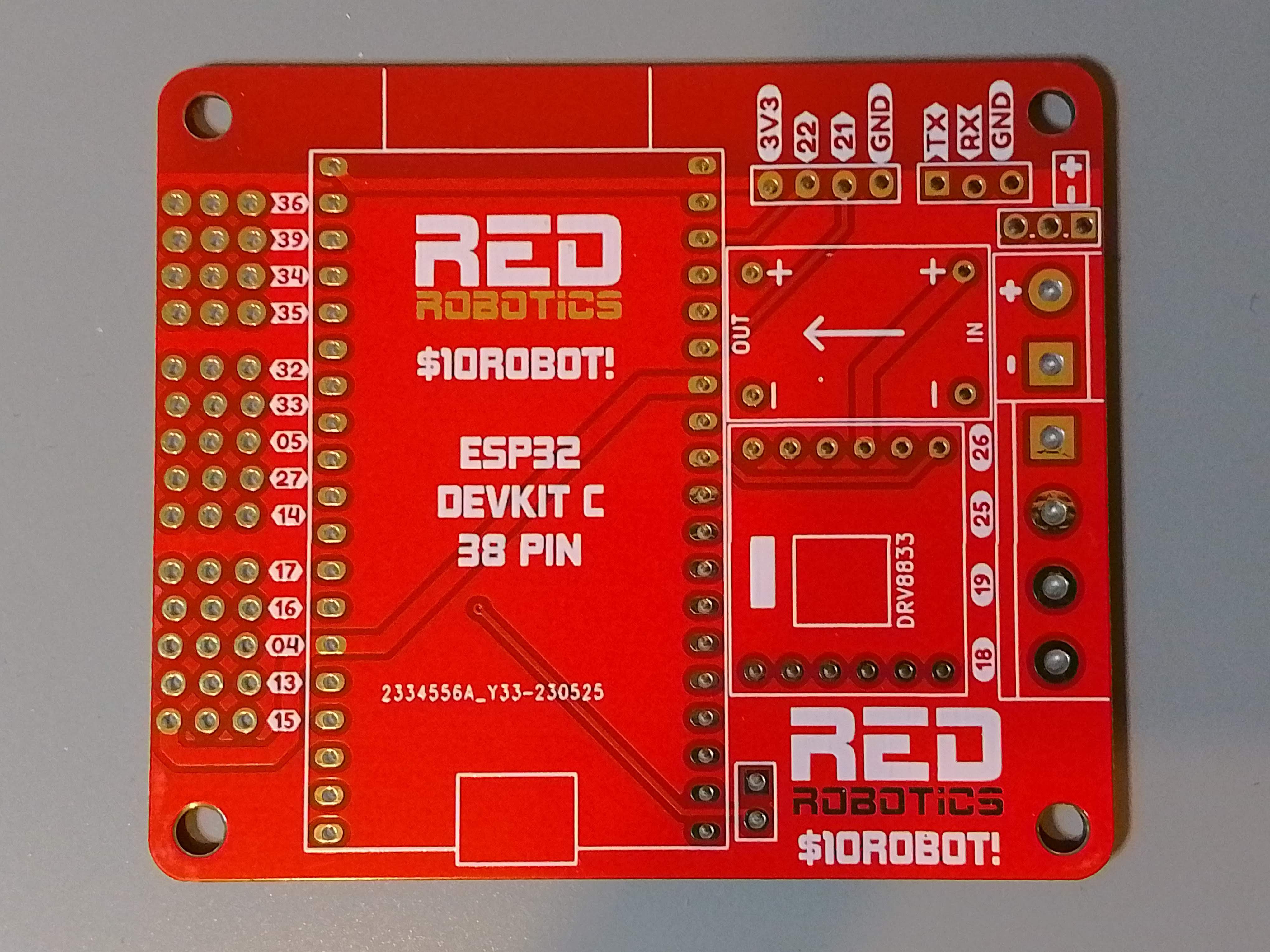
PCB = $0.40
Screw Terminals = $0.10
Header Pins = $0.10
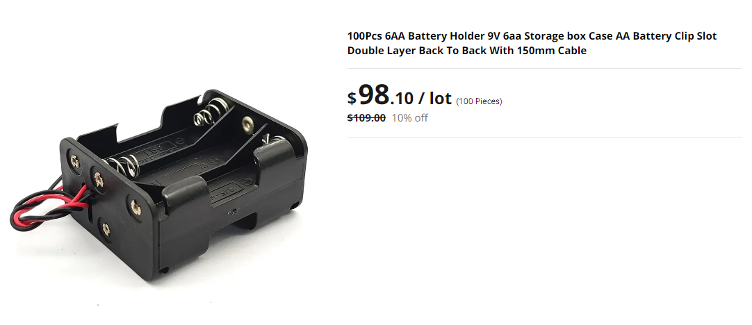
6 x AA Battery holder (not including batteries) = $1.00
Total components = $8.00
These are of course subject to change but It's a good starting point.
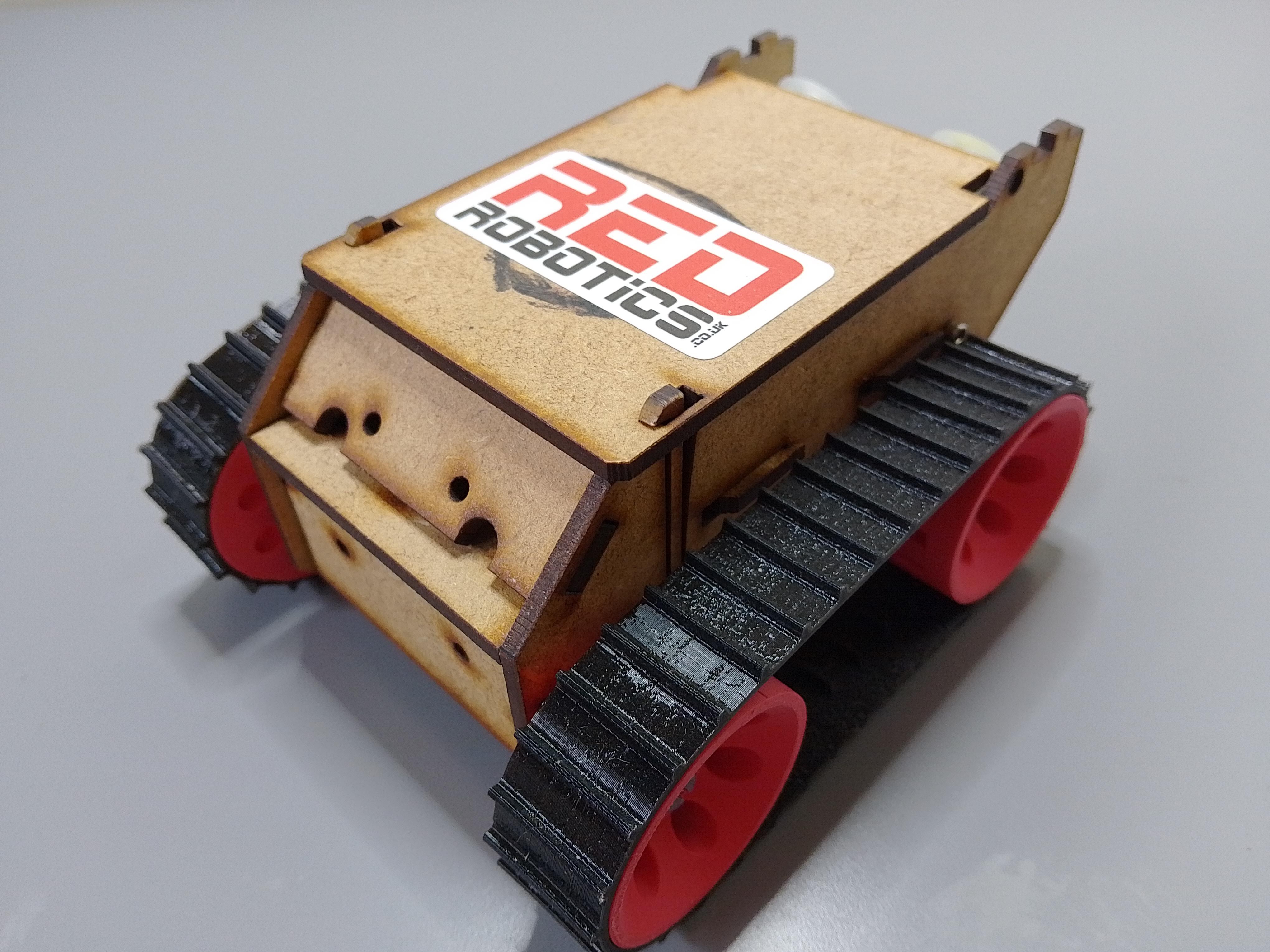
This leaves $2.00 for materials for laser cutting or 3D printing to make a chassis – I think this is possible!


 Jithin Sanal
 thjubeck
 Guillermo Perez Guillen