Collin Matthews
After purchasing a semi-functional Fluke 412b 2kV power supply, I set out to fix it. The output voltage was ~1/3 of the programmed voltage. The regulation circuitry all was referenced to the high voltage output and made troubleshooting difficult, so I decided to first check if the 2 8068 power tubes were good and the 83A1 regulator tube.
I had also recently scored a cheap electrophoresis power supply on eBay. If you have a project that needs a few kV of electricity with 10-100W, I recommend checking them out, you can get some for under $100. The only down side is they are effectively bi-polar outputs, that also monitor for any leakage current to ground similar to a GFCI outlet. This means you can not connect any ground referenced equipment like an oscilloscope easily or safely.
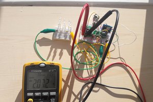
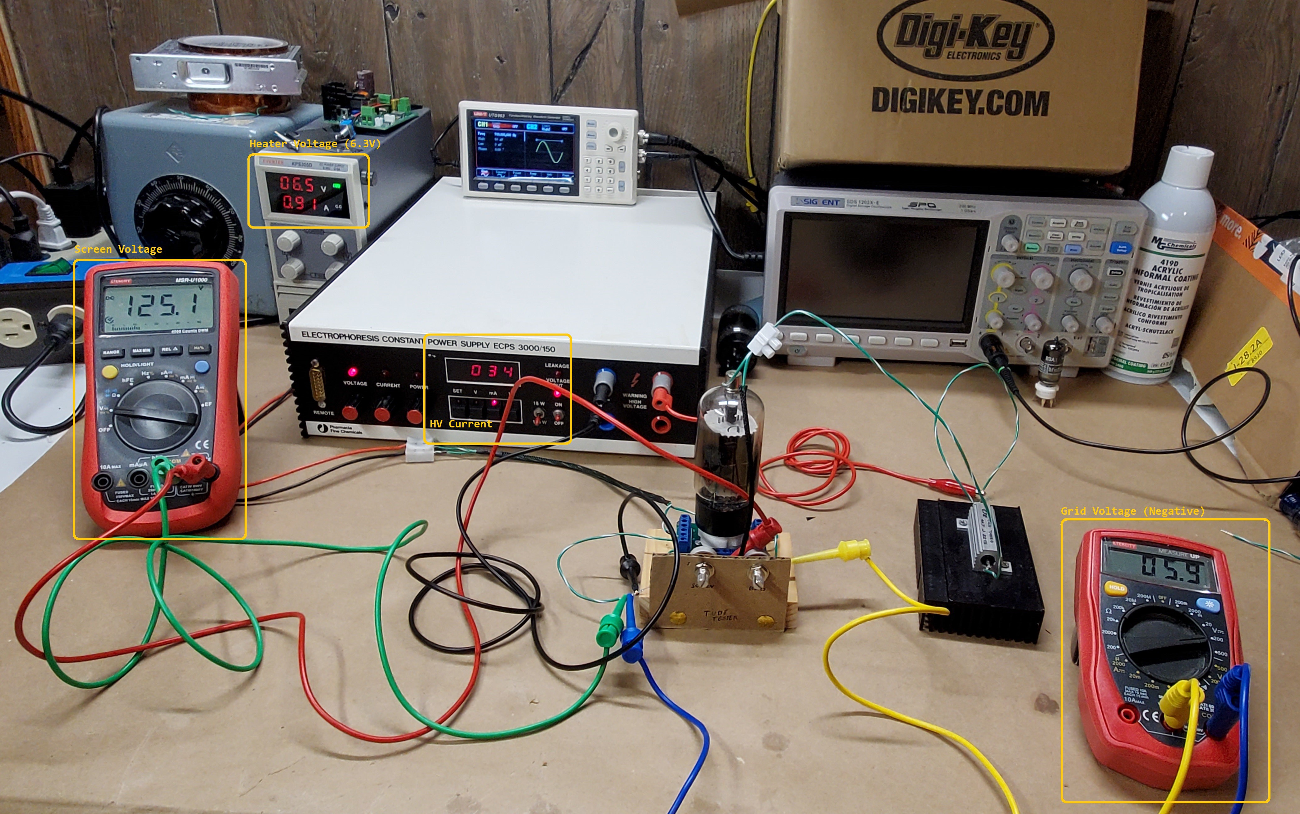
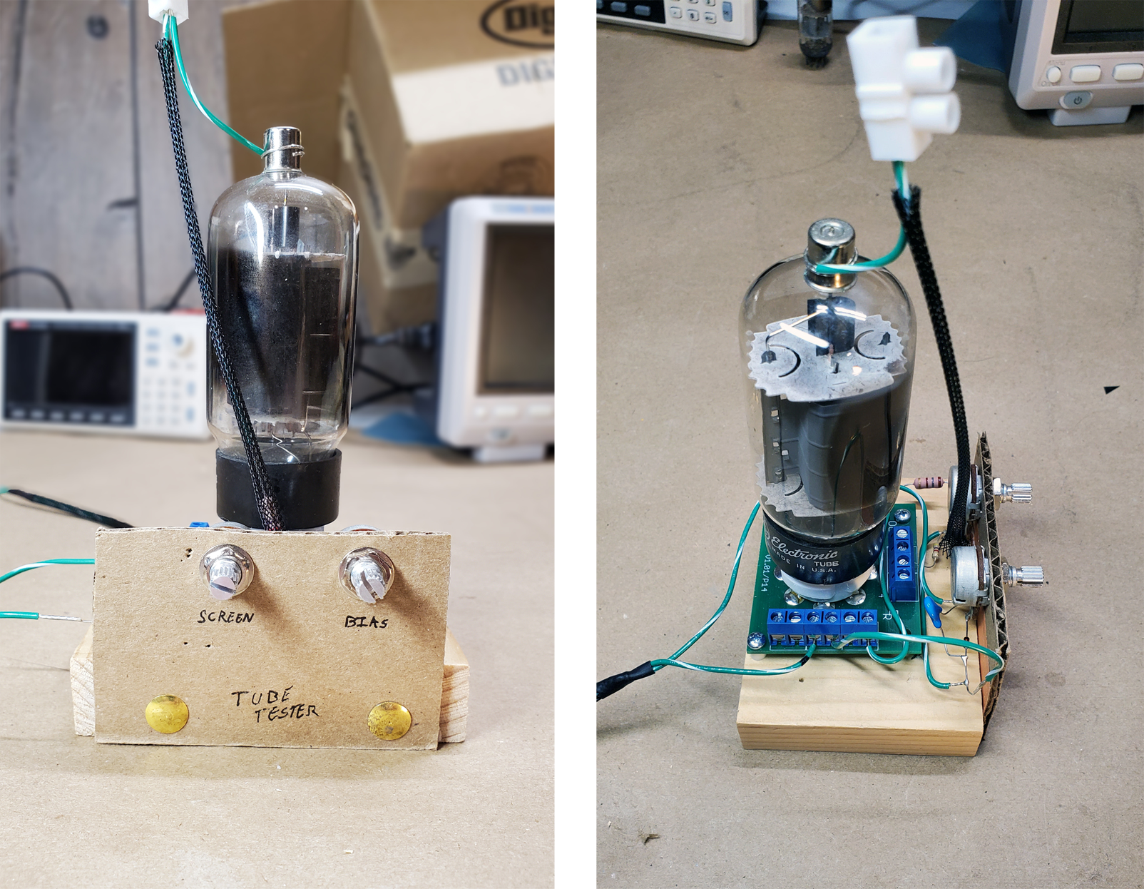
I used a 8 pin octal socket to screw terminal board I had also bought off eBay years earlier to make the connections easier instead of alligator clips directly to the tube terminals. Below is the effective schematic made of 2 power suppliers and 2 multi-meters. I took some time to put some potentiometer in a small face plate to make adjustments easier.
Check out the video about it, or the images below:
The supply used the tube with around 500V across it, and up to 20mA, so I decided the circled recommended operating point below would be good to replicate. It pushes the tube to its power limit, so I figured if I can get close to the current at the recommended values the tube is in great shape.
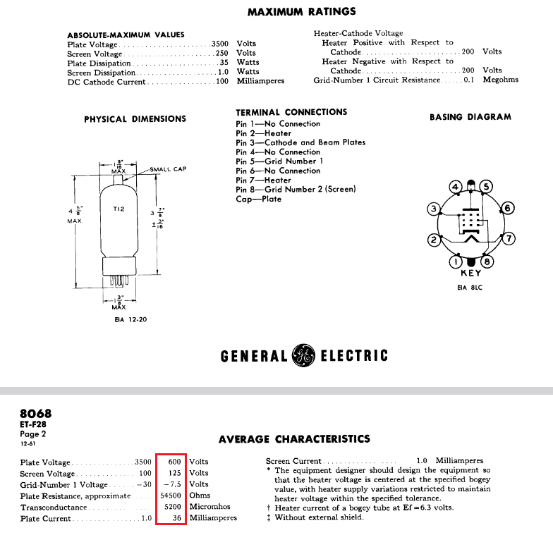
You can see it in the YouTube video I shot about this, but yes, the power tubes turned out alright. The voltage regulator tube as well, although that had a simpler setup of a series resistor and leads right to the power supply instead of my fancy octal fixture.
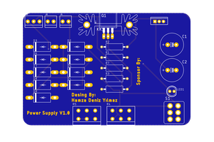
 Hamza Deniz Yılmaz
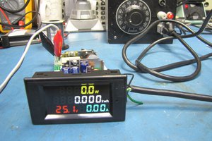
 Mario Ninic