kelvinA
Navigation
Prior Reading
Contents
The title tag system is explained here, and the table is updated when a change occurs. Notable logs have bold L# text.
Preface
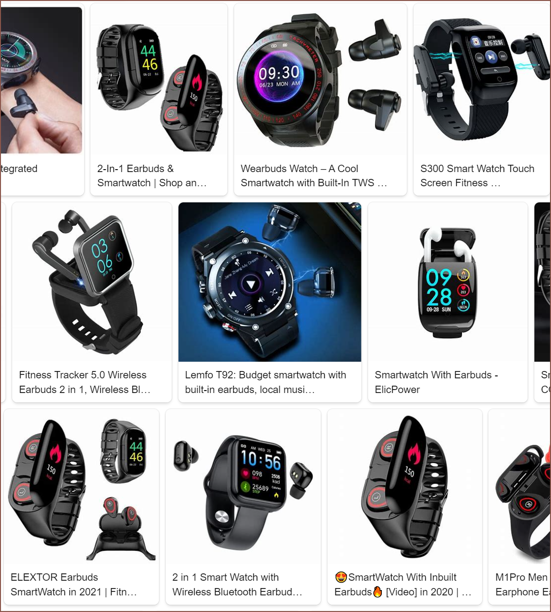
This project is to research if I can get most of the benefits of the #Teti [gd0022] and #Tetent [gd0090] system whilst having something much more portable than a desktop PC with a handle.