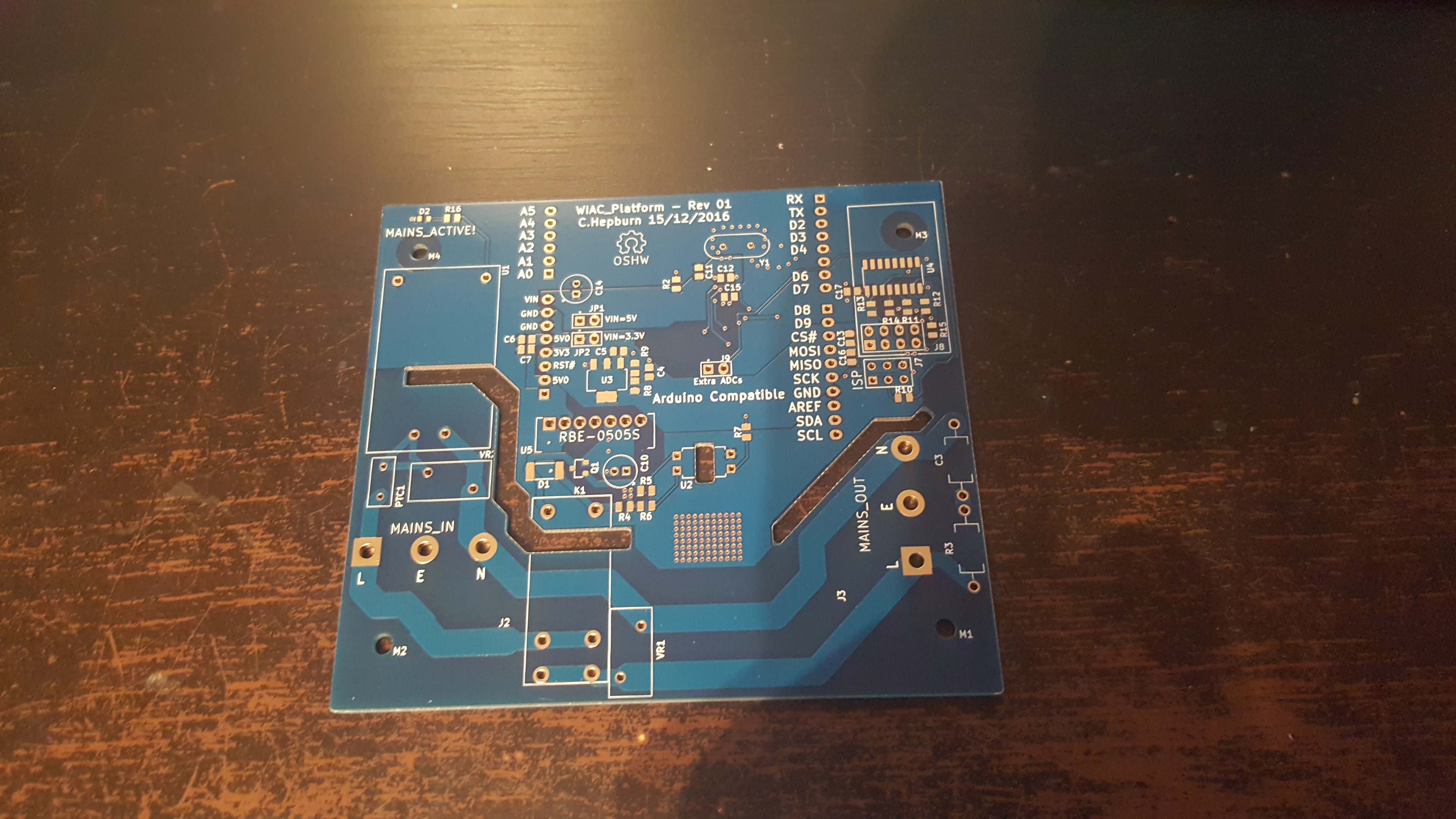
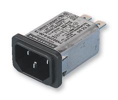
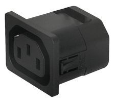
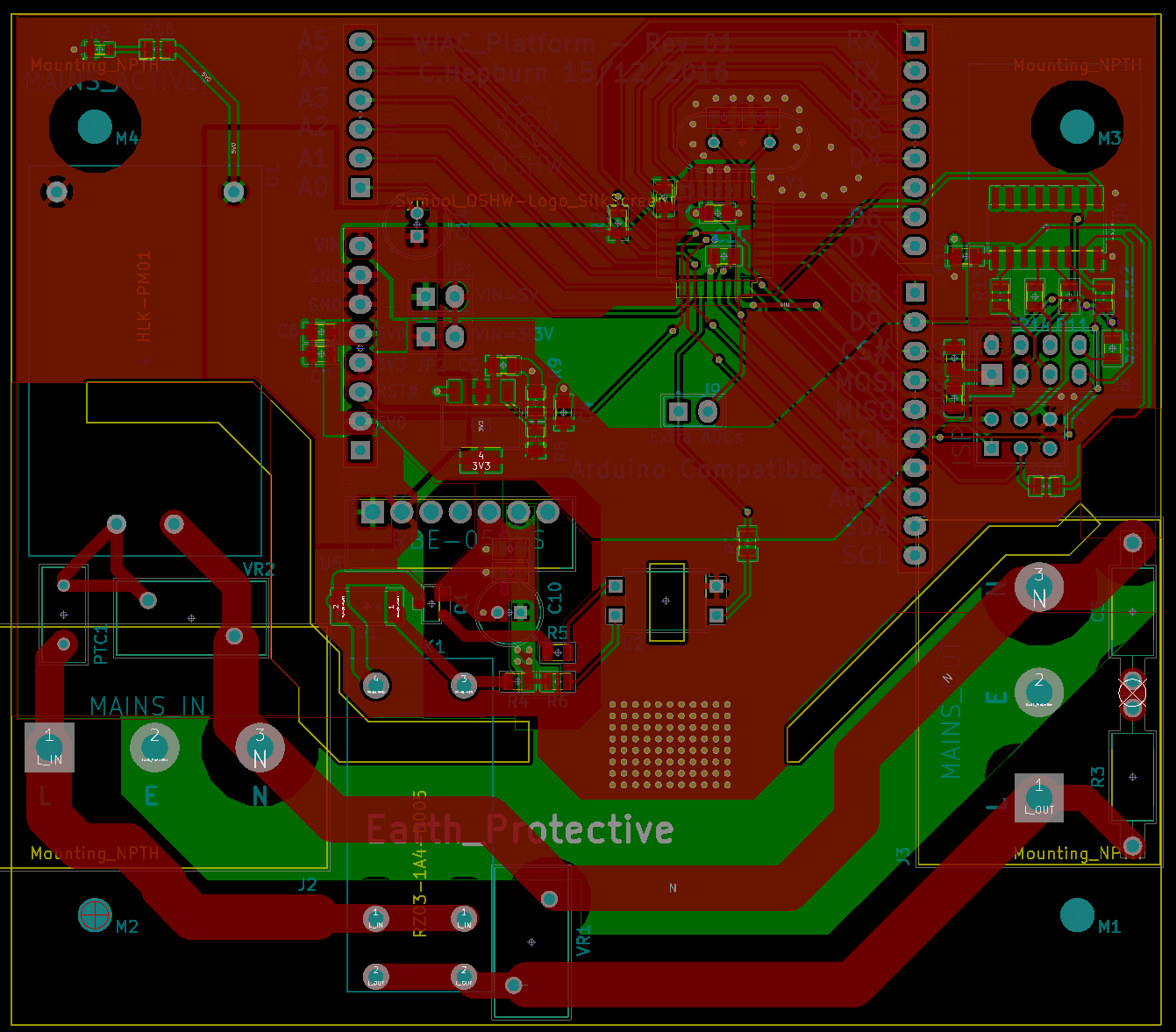
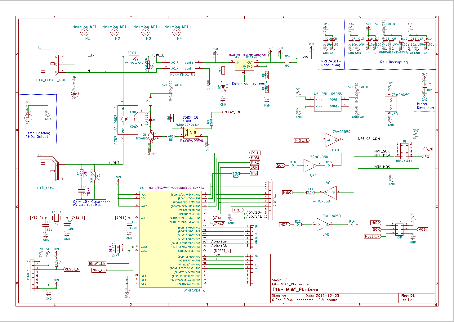
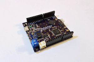
This design is an Arduino compatible ATMega 328 design which has a switchable 15A rated mains pass through with some emphasis on safety and protection. IPC2221 clearances and creepage has been used where possible to reduce the potential for a fault to hurt the user. The mains inputs have MOVs to protect against any potential spikes coming through as well as a high quality EMI filter which provides high frequency filtering of the mains input via a common mode choke, Y class capacitors and a Bleeder resistor to discharge any residual charge in the device when unplugged. The design is also fused on the high side with a PPTC which will stop any temporary faults, a future revision may incorporate a replaceable fuse too (In the UK plugs come with fuses built in).
The design takes advantage of a cheap AC to DC converter which has been tested by the community to be bother reliable and safe. It gives an isolated DC output which has been bonded strongly to earth for safety as the user has access to the Arduino connectors. An isolated DCDC has been used to power the relay to protect the user and the circuit in case of a relay failure.
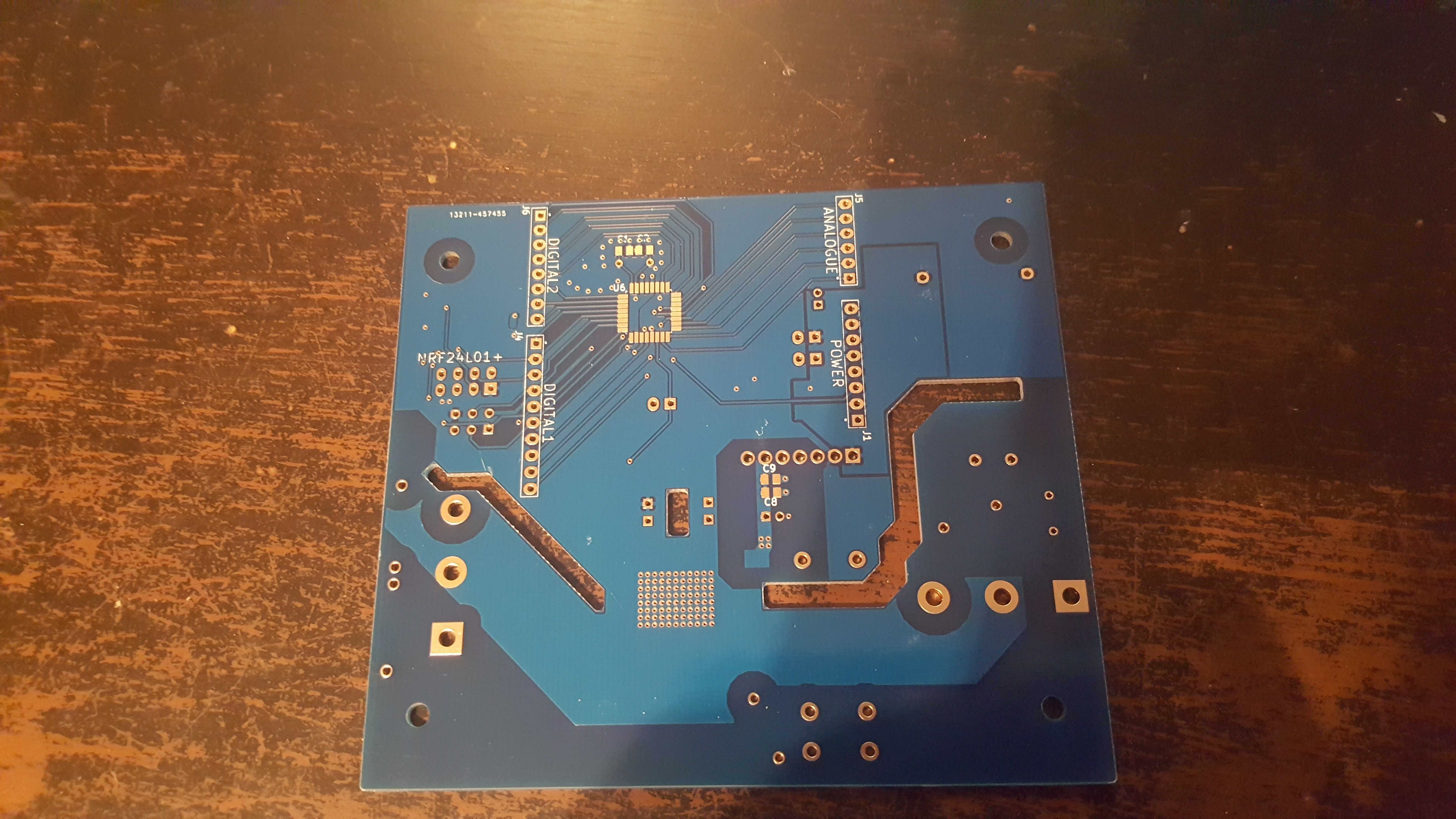
On the low voltage side an ATMega328 acts as the main microprocessor. The wireless side of the device is supplied by the NRF24L01+ modules which can be bought cheaply from China and easily formed into a star or mesh topology network which is desirable for home automation. One idea if desirable would be to change this to a Wi-Fi design instead.
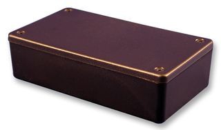
Overall the idea of the project is to provide an easy to use mains passthrough with integrated wireless functionality for users to tinker with. Ideally it should just be plug and play and look like a standard Arduino from the outside whilst providing isolation and protection from the high voltages present in the mains during runtime.
 Timothy Woo
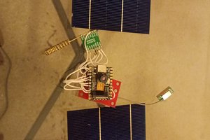
 Alistair Jordan
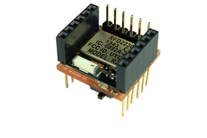
 James Cannan